Solid-State interferometric interrogator and multiplexer for
high-speed dynamic and absolute FBG wavelength measurement
Philip Orr, Marcus Perry, Grzegorz Fusiek and Paweł Niewczas
Institute for Energy and Environment, Department of Electronic and Electrical Engineering,
University of Strathclyde, Glasgow G1 1XW, United Kingdom
Tel: +44 (0)141 548 4841, Fax: +44 (0)141 548 4872
E-mail: [email protected]
ABSTRACT
We present a solid-state FBG array interrogator and multiplexer capable of determining absolute FBG wavelengths and of providing high-speed, high-resolution static and dynamic measurements. Using a described procedure, deployable on multiplexing passive-interferometric schemes, the system is able to determine initial sensor wavelengths and thereafter track wavelength changes with interferometric resolution. The scheme allows high-resolution interrogation of FBG sensor arrays to be applied to many industrial applications, where previously the lack of combined absolute and quasi-static wavelength measurement precluded the use of interferometric techniques. Using a preliminary laboratory embodiment, we demonstrate a wavelength determination accuracy of <0.3 nm and a measurement resolution of 10 fm/√Hz, and propose pathways to improved performance and miniaturisation.
Key words:fibre Bragg gratings, absolute wavelength, interrogation systems, sensor multiplexing
1. INTRODUCTION
Fibre Bragg grating (FBG) sensors are now ubiquitous in the field of optical instrumentation, primarily due to their robustness, low cost, high performance, and simplicity of interrogation and multiplexing1,2. However, the performance of an FBG sensor array, such as the achievable interrogation rate, accuracy, and resolution of each discrete sensor, is determined primarily by the interrogation system deployed. While FBG wavelength measurement has been realised by a number of methods (including interferometry and prism/CCD arrays3), arguably the most common uses a combination of a broadband light source, a tunable filter (either scanning Fabry-Perót or acousto-optic4) and a photodetector. In such ‘tuned’ schemes, multiplexing is achieved relatively straightforwardly at the expense of measurement resolution and rate. This trade-off is generally justified, however, by the ability of these sensors to provide an absolute measure of FBG wavelengths, as this is a pre-requisite for the deployment of FBG sensor arrays in many industrial applications.
2. SYSTEM DESIGN
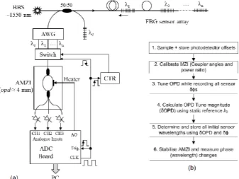
The proposed sensor interrogation scheme is illustrated in Fig. 1(a). A broadband source illuminates the sensor array, within which each FBG reflects at a unique wavelength λ1 – λn. Sensor FBG reflections are coupled into a series of demodulation elements to enable multiplexing, wavelength determination, and wavelength tracking. Wavelength division multiplexing is achieved at high speed using a technique described previously6, whereby an optical wavelength switch comprising an arrayed-waveguide grating (AWG) and optical path switch are utilised to switch (with a transition time of the order of ns) between flat-top spectral bins that are assigned uniquely to each sensor in the array. Individual sensor reflections are therefore time-sequenced and delivered serially to an asymmetrical Mach-Zehnder interferometer (AMZI) that is thermally stabilised and incorporates the capability for brief tuning of a single path.
By utilising an AMZI terminating in a 3×3 coupler at the point of interference, a passive, ratiometric phase-demodulation algorithm such as Todd’s8 may be deployed in order to continually track phase differences while retaining immunity to fluctuations in input optical power or attenuation en route to sensors. In the preferred embodiment, the immediacy of the switching multiplexer may be exploited in order to perform oversampling of each FBG reflection, enabling anti-alias filtering for noise reduction after ADC by synchronously driving the sampling clock at an integer multiple of the band-switching clock. The proposed architecture therefore allows for multiplexing rates limited by band-switching speed and an oversampling factor limited by ADC capabilities.
Figure 1. (a) Proposed FBG interrogator and multiplexer. AWG is arrayed waveguide grating, AMZI is asymmetric Mach-Zehnder interferometer, BBS is broadband source. (b) Procedure for interrogator initialisation and determination of initial sensor wavelengths.
[image:2.595.128.466.295.548.2] 2nd
(1)
where n is the MZI core index (tunable by heating) and d is the physical path difference. For a reference at λref and a sensor at λ1, the unique ratio relating the phase changes δϕref and δϕ1 during an arbitrary path unbalance tuning of δ(nd) can be shown to be
1
1 ref
ref
(2)
which may be used straightforwardly to calculate λ1 and all other sensor wavelengths in the same manner. This assumes that the sweep time is sufficiently less than any present perturbations on all sensors such that sensor wavelengths can be assumed to be stable during the procedure. It is clear from (2) that error is introduced both by uncertainty in the reference wavelength, and by noise in the measured values of the phase excursions.
3. SIMULATION OF ABSOLUTE WAVELENGTH DETERMINATION
To demonstrate the determination of absolute wavelength, a simulation has been constructed based on the system in Fig. 1(a) incorporating phase demodulation of sensor and reference wavelengths using Todd’s passive algorithm8. Separate phase unwrapping and a phase noise floor of 100 μrad/√Hz on each sensor (corresponding to the noise floor of our laboratory scheme) are included. As with practical interferometric interrogators, the measurements are referenced (zeroed) to “switch on” time, and no absolute measurements are initially available. Reference and sensor wavelengths of 1560 nm and 1550 nm, respectively, are simulated in this case.
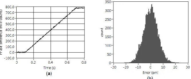
To simulate the tuning of phase unbalance, an initial OPD of 4 mm is detuned by 1% at a rate of 50 μm/s – parameters which are straightforwardly achieved in planar interferometers9. As shown in Fig. 2(a), the OPD is held constant for 100 ms both prior to and following detuning, during which periods averaging is performed to yield the pre- and post-tuning phase differences (reducing the impact of phase noise). The calibration process therefore takes 0.5 s in total in this example – in practice, higher interrogation rates will worsen phase noise but will allow for an increase in tuning rate and hence reduce initialisation time. An interrogation rate of 1 kHz is utilised in this simulation, which is sufficient to correctly process wrapping phases at a tuning rate of 50 μm/s without discontinuities arising.
Figure 2. (a) Incurred difference between phase excursions in reference and sensor wavelength during OPD tuning. Tuning rate 50 μm/s, total detuning 40 μm (1% of initial OPD), interrogation rate 1 kHz. (b) Histrogram (10,000 iterations) of sensor wavelength
determination error. Standard deviation is 5.61 pm.
[image:3.595.133.467.455.594.2]influence of phase noise can be reduced by increasing the span between reference and sensor wavelengths, which will produce a larger differential phase (δϕref – δϕn = 2π∙δOPD∙(1/λref – 1/λn)), and hence a larger signal-to-noise ratio.
4. PRELIMINARY LABORATORY TESTS
In order to demonstrate practically the performance of the proposed scheme (both in terms of absolute accuracy, and of static and dynamic resolution), the system in Fig. 1(a) has been constructed with a limited number of multiplexed sensors. For comparison with the simulation in Section 3, an athermal grating (without active temperature control) is utilised as the wavelength reference λref located at 1559.96 nm. A sensing FBG located at 1549.14 nm is mounted on a cantilever, which was stabilised during the initialisation process. The AMZI, incorporating a path difference of 4.58 mm, is an all-fibre construction fabricated between the output pigtails of 1×2 and 3×3 couplers by fusion splicing. To isolate the MZI from vibration and to hinder heat transfer during tuning, the device is bonded to a glass slab by epoxy. Thermal tuning of the OPD is facilitated by a resistive heater in thermal contact with a single MZI arm. The ADC unit is configured to sample at 4 kHz with an oversampling factor of 4, thus providing a measurement rate of 0.5 kHz per sensor.
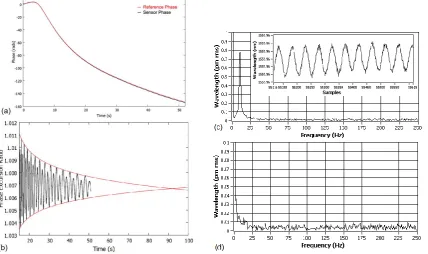
Figure 3. (a) Phase excursions of sensor and reference FBG reflections during OPD tuning (~1% of initial OPD, i.e. 40 μm). (b) Convergence of sensor wavelength determination process on correct λ1/λref ratio of 1.006598. (c) Amplitude spectrum and time plot
(inset) of sensor wavelength during small (~5 pm rms) 10 Hz perturbation of cantilever. (d) Spectral noise floor (<10 fm/√Hz) of system recorded using athermal reference FBG.
An OPD detuning of approximately 140 rads (or 1%) is produced during this experiment, allowing direct comparison with the simulation in Section 3. Fig. 3(a) shows the phase excursions of reference and sensor FBGs during OPD tuning, while Fig. 3(b) illustrates the convergence of the calculated ratio δϕref/δϕ1. It can be seen that the ratio calculation converges on the ideal value of 1.00659 for the particular reference and sensor wavelengths utilised in this experiment. A repeatable accuracy of <0.3 nm has been achieved in this experiment by determining the unique ratio through averaging, which can be improved in future embodiments by using different techniques as discussed in the following section.
[image:4.595.87.516.262.516.2]shift (Fig. 3(c)). Simultaneously, a noise spectral density of <10 fm/√Hz is visible on the athermal reference grating (Fig. 3(d)).
5. DISCUSSION
As discussed by the authors previously11, there is an inherent nonlinearity associated with the passive interferometric phase demodulation technique utilised here, which becomes noticeable only under conditions of very large signals. A nonlinear sensitivity is produced as FBG reflections pass over fringe maxima and minima and are “pulled” slightly towards the maxima locations. In this work, the large OPD tuning magnitude induced to allow calculation of initial sensor wavelengths gives rise to such oscillations in the converging ratio calculation of Fig. 3(b). As the phase excursions of the reference and sensor FBGs diverge, the impact of the nonlinear responses lessens, allowing the calculation of sensor wavelengths to be performed regardless. However, there is clear potential for further work in improving the speed and accuracy of the ratio estimation using signal processing techniques, by reducing the linewidth of the FBGs, or by utilising fibre laser sensors.
Due to the solid-state nature of the proposed system, its miniaturised implementation may be achieved using a silicon photonics platform whereby the AWG, switching, tunable AMZI, and photodetection elements of Fig. 1(a) may be incorporated on a single silicon chip12. Given the tremendous growth in this field at present, it is likely that low-cost mass production of such interrogators will be best facilitated in this manner.
6. CONCLUSIONS
In this paper we have described an FBG interrogator and multiplexer that combines absolute sensor wavelength determination with interferometric resolution for static and dynamic measurements. An initialisation procedure for utilising a switched-band wavelength multiplexing technique to determine the starting wavelengths of all multiplexed sensors was described, simulated, and demonstrated practically. A preliminary laboratory demonstration of the system has been shown to be capable of an absolute wavelength determination accuracy of <0.3 nm and thereafter a wavelength tracking resolution of <10 fm/√Hz for static and dynamic measurements, and is therefore likely to be applicable to a wide range of demanding industrial measurement applications. The performance of the wavelength determination technique was discussed and shown to be improvable through future work focussed on signal processing, the reduction of sensor linewidths, and implementation of the scheme on a silicon photonics platform.
ACKNOWLEDGEMENTS
This work was supported by the Engineering and Physical Sciences Research Council.
REFERENCES
[1] Kersey, A. D. et al, “Fiber Grating Sensors,” J. Lightwave Tech. 15(8), 1442-1463 (1997)
[2] Mendez, A., “Fiber Bragg grating sensors: a market overview,” Proc. SPIE 6619, p. 661905 (2007)
[3] Ezbiri, A., Kanellopoulos, S. E., and Handerek, V. A., “High resolution instrumentation system for fibre-Bragg grating aerospace sensors,” Opt. Comm. 150, 43–48 (1998)
[4] Boulet, C., Webb, D. J., Douay, M., and Niay, P., “Simultaneous interrogation of fiber Bragg grating sensors using an acoustooptic tunable filter,” Phot. Tech. Lett. 13(10), 1215–1217 (2001)
[5] Johnson, G. A., Todd, M. D., Aulthouse, B. L. and Chang, C. C., “Fiber Bragg grating interrogation and multiplexing with a 3×3 coupler and a scanning filter,” J. Lightwave Tech. 18(8), 1101–1105 (2000)
[6] Orr, P. and Niewczas, P., “High-speed, solid-state, interferometric interrogator and multiplexer for fiber Bragg grating sensors,” J. Lightwave Tech. 29(22), 3387–3392 (2011)
[7] Majumder, M., Gangopadhyay, T. K., Chakraborty, A. K., Dasgupta, K., Bhattacharya, D. K., “Fibre Bragg gratings in structural health monitoring – Present status and applications,” Sens. Act. A: Phys. 147, 150-164 (2008)
[8] Todd, M. D., Johnson, G. A. and Chang, C. C., “Passive light intensity-independent interferometric method for fibre Bragg grating interrogation,” Elec. Lett. 35(22), 1970–1971 (1999)
[10]Lo, Y. L. and Kuo, C. P., “Packaging a fiber Bragg grating without preloading in a simple athermal bimaterial device,” IEEE Trans. Advanced Packaging 25(1), 50–53 (2002)
[11]Orr, P. and Niewczas, P., “Passive, Multiplexable Measurement of Magnetic Field Strength and Temperature Using PM Fibre Bragg Gratings and Chiral Fibre Devices,” Proc. 20th Int. Conf. on Optical Fiber Sensors (2009)