Numerical study of a passive solar still with separate condenser
A. Madhlopa*,† and C. Johnstone
Energy Systems Research Unit, Department of Mechanical Engineering, University of Strathclyde, 75 Montrose Street, Glasgow G1 1XJ, United Kingdom.
Abstract
A passive solar still with separate condenser has been modeled and its performance evaluated. The system
has one basin in the evaporation chamber and two basins (middle and upper) in the condenser chamber, with a
glass cover over the evaporator basin and an opaque condensing cover over the upper basin. The evaporator,
middle and upper basins yield the first, second and third effects respectively. The top part of the condensing
cover is shielded from solar radiation to keep the cover relatively cool. Water vapor from the first effect
condenses under the glass cover while the remainder of it flows into the condenser, by purging and diffusion,
and condenses under the liner of the middle basin. The performance of the system is evaluated and compared
with that of a conventional solar still under the same meteorological conditions. Results show that the
distillate productivity of the present still is 62 % higher than that of the conventional type. Purging is the most
significant mode of vapor transfer from the evaporator into the condenser chamber. The first, second and third
effects contribute 60, 22 and 18 % of the total distillate yield respectively. It is also found that the productivity
of the solar still with separate condenser is sensitive to the absorptance of the evaporator basin liner, mass of
water in the evaporator and middle basins, and wind speed. The mass of water in the upper basin has a
marginal effect on distillate production. Other results are presented and discussed in detail.
Keywords: Condenser, evaporator, natural circulation, simulation, solar radiation shield
*
Corresponding author: E-mail: [email protected] †
1. Introduction
Clean water is essential for good health, which relates to socio-economic development. Nevertheless, safe drinking water is scarce, especially in the developing countries due to the limitation of financial and other resources. The quality of water can be improved through the use solar stills. This technology is suitable for exploitation in the developing countries because it is cheap and requires little maintenance [1].
A basic solar distillation system has a thin layer of water in a shallow basin, transparent cover over the water and channel for collecting the distillate. Saline water in the basin is heated by solar radiation that passes through the transparent cover and is absorbed by the bottom part of the still basin. Vapor rises from the hot water and condenses when it gets into contact with the inner surface of the transparent cover. The condensate (clean water) is collected through a channel fitted along the lower edge of the transparent cover.
Based on various modifications, solar stills are broadly classified into active and passive systems [8]. In solar stills of the active variety, additional thermal energy from an external mode (such as a flat plate or concentrator collector) is supplied to the evaporator to
augment the temperature of the water in the basin. Tiwari et al. [8] report that active solar stills are suitable for commercial production of distilled water. No outside heat is
employed in the passive variety of solar stills. In both classes of stills, water vapor flows from the evaporator to the condensing cover by natural (convection, diffusion and purging) or forced circulation. Natural circulation does not require a blower, thereby reducing costs associated with forced circulation. This study focuses on a passive solar still with external condenser and natural circulation of water vapor from the evaporator to the condensing unit.
materials to construct. However, the condenser unit is located in the shadow zone of the still (without a solar radiation shield), which exposes the condensing cover to diffuse and ground-reflected solar radiation components. Moreover, the sun is overhead and on either side of the latitude at a tropical site, thereby allowing the global solar radiation to reach and heat the bare condensing cover, and significantly reduce the cover-water temperature difference. This would adversely affect the thermal efficiency of the still. Consequently, there is limitation of time and space to the application of a solar distillation system with an unshielded separate condensing cover.
In the present work, a single-slope passive solar still with an external condenser has been studied theoretically. The performance of both the present solar still (PSS) and CSS was simulated under similar meteorological conditions. Simulation results are presented and discussed in this paper.
2. System description and modeling
A solar still with separate evaporator and condenser chambers has been studied numerically. The major components of the system are a) a horizontal basin 1 with saline water in the evaporator chamber (first effect), b) basin 2 with saline water (second effect), c) basin 3 with saline water (third effect), d) condensing cover and e) opaque insulation shield over the condensing cover (Fig.1a). Both basins 2 and 3 are located in the
rises up and condenses on the inner side of the glass while part of the vapor flows into the condensing chamber by purging and diffusion where it condenses on the outer surface of the middle basin liner, thereby recovering part of the heat from the first effect. There is a condensing cover directly above the upper basin, with an inclined air channel (with a single open end) over the cover for cooling. The condensing cover is shielded from solar
radiation by an opaque insulation cover, which forms part of the air channel. Distillate is collected by drainage channels on the bottom lower parts of the glass cover, middle basin liner, upper basin liner and condensing cover.
A mathematical model was developed to simulate the performance of the CSS and PSS under the same meteorological conditions (with γ=180o). It was assumed that:
a) the two solar stills are air-tight,
b) purging and diffusion stop when the temperature of water in the middle basin exceeds that of the lower basin, and
c) ground-reflected solar radiation does not reach saline water in the evaporator basin.
With these assumptions, the heat balance equations for the present solar still components are as follows:
Glass cover (gc)
(
w gc)
gc cgca(
gc a)
gc rgcsk(
gc sk)
gc w ef gc gc gc gc p
gc
A
F
G
A
h
T
T
A
h
T
T
A
h
T
T
dt
dT
C
m
,=
+
1 1−
−
, −−
−
, −−
(1)
+ + + +
= cw−gc ew−gc rw−gc
gc h
R Rh
R Rh
h , 1 , 1 , 1
1
Basin liner 1 (bl)
(
)
(
)
}{ 1 ,1 1 1 1 1
1 1 1 ,
1 w b ef cb w b w bo b a
b b p
b A F G h T T U T T
dt dT C
m = − − − − − (3)
Water in basin 1 (wl)
(
)
[
w ef cb w b w]
d w w w(
w gc)
s sw(
w a)
w w w P
w A F G h T T m H A h T T A U T T
dt dT C
m = 1 1 + ,1− 1 1− 1 − 1− 1 1 1− − 1 1−
1 1 ,
1 (4)
gc w r gc w e gc w c
w h h h
h 1 = , 1− + , 1− + , 1− (5)
(
ec)(
ve vc)
d D x
m = Aec / ϕ −ϕ (6)
Basin liner 2 (b2)
(
1)
1 2 , 2 2(
2 2)
12 2 ,
2 w pu w gc d w b cb w b w
b b p
b A h T T m H A h T T
dt dT C
m = − + − − − (7)
R h
R h
hpu cw gc ew gc
+ + + = − − 1 1 1 , 1 , (8)
Water in basin 2 (w2)
(
b w)
w w(
w b)
s sw(
w a)
w b c b w w p
w A h T T A h T T A U T T
dt dT C
m 2 = 2 , 2− 2 2 − 2 − 2 2 2 − 3 − 2 2 −
2 ,
2 (9)
3 2 , 3 2 , 3 2 ,
2 cw b ew b rw b
w h h h
h = − + − + − (10)
Basin liner 3 (b3)
(
2 3)
3 , 3 3(
3 3)
22 3 3 ,
3 w w w b b cb w b w
b b p
w A h T T A h T T
dt dT C
m = − − − − (11)
Water in basin 3 (w3)
(
b w)
w w(
w co)
s sw(
w a)
w b c b w w p
b A h T T A h T T A U T T
dt dT C
m 3 = 3 , 3− 3 3 − 3 − 3 3 3 − − 3 3 −
3 ,
3 (12)
co w r co w e co w c
w h h h
Rate of evaporation (me)
(
)
(
)
(
)
1 3 1 3 3 , 3 2 1 3 2 3 2 , 2 1 1 1 , w d w w co w co w e w w w b w b w e w w gc w gc w e e A m H A T T h A H A T T h A H T T hm = − − + − − + − − + (14)
The heat flux (Qe) due to evaporation can be written as:
(
)
(
)
(
)
1 1 1 3 3 , 3 1 2 2 3 2 , 2 1 1 , w w d w co w co w e w w b w b w e w gc w gc w e e A H m A T T h A A T T h A T T hQ = − − + − − + − − + (15)
The distillate yield (mdw) and efficiency of the system (η) in a time interval of (t2-t1) are calculated from: dt m m t t e dw =
∫
2 1 (16)
∫
∫
= 2 1 2 1 100 t t gh t t e dt G dt Qη (17)
It should be mentioned that the heat balance equations for the CSS are similar to those of the components of the evaporator unit of the PSS with the following modifications:
Glass cover (gc)
gc w r gc w e gc w c
gc h h h
h = , 1− + , 1− + , 1− (18)
Water in basin (w1) 0
=
d
m (19)
Rate of evaporation (me)
1 1
1
,w gc( w gc)/ w e
e h T T H
m = − − (20)
Fgc= αgc (21) Fwl =αwl (1- αgc - ρgc) (22) Fbl =αbl[1-αgc-ρgc-ρwl (1-αgc-ρgc)- Fwl] (23) Physical properties used in the present study are: Cp,gc=750 J kg-1 K-1, Cp,bl= Cp,b2 = Cp,b3 =477 Jkg-1K-1, αwl=0.05, ρwl=0, ρbw=0.05, εgc=0.88, εw=0.96 and εco=0.80. At normal incidence, the values of αgc and ρgc were taken to be 0.10 and 0.12 respectively. It was assumed that the condensing cover and the basin liner were made of galvanized iron sheet while the solar shield was made of plywood. A temperature-dependent correlation was used to calculate the specific latent heat of water vaporization [13]. The saturation vapor pressure inside the solar still was calculated using a correlation reported by ASHRAE [14], and other physical properties of water (k,α′, β′, ν and ρ) were computed from temperature-dependent correlations [15]. The densities of water vapor in the evaporator (ϕve) and condenser (ϕvc) chambers were calculated using Eq.(24), at 0.5(Twl+Tgc) and 0.5(Tb2+Ta) respectively. The reference design, operational and meteorological parameters for both the CSS and PSS are presented in Table 1.
ϕ=P/(RvT) (24)
Heat loss from the top of the glass cover to the environment is predominantly by convection (to ambient air) and radiation (to sky). Wind influences the convective heat transfer from the top part and the wind coefficient of heat transfer is calculated from [16]:
> ≤ +
=
− −
− 0.8 1
1 ,
5 ,
15 . 6
5 ,
3 8 . 2
ms V
V
ms V
V h
wd wd
wd wd a
gc
c (25)
) )(
( 2 2
,gc sk gc gc sk gc sk
r T T T T
h − =σε + + (26)
with the following correlation for sky temperature [17]: 1.5
a sk 0.0552T
T = (27)
The evaporation and condensation processes involve the transfer of both heat and mass. Consequently, relevant correlations are used to estimate the coefficients of internal
convective and evaporative heat transfers from hot water to each of the condensing surfaces [18]:
(
)
(
)
3 / 1 , 268900 884 . 0 − − + − = − w w cs w cs w cs w c P T P P T Th (28)
(
)
cs w cs w cs w c cs w e T T P P h h − − = − − , , 016273 . 0 (29)In addition, there is internal heat radiation from hot water to each of the condensing surfaces. The coefficient of internal radiative heat transfer is estimated from [12]:
) )(
( 2 2
,
,w cs wcs w cs w cs
r T T T T
h − =σε + + (30)
1 , 1 1 1 − − + = cs w cs w ε ε
ε (31)
The coefficient of convective heat transfer from the middle and upper basin liners to saline water is calculated according to Incropera and Dewitt [19], assuming the basins are inclined to the horizontal:
hc=Nu k/S (32)
(
)
[
]
2 27 / 8 6 / 9 6 / 1 Pr / 492 . 0 1 387 . 0 825 . 0 + + = RaPr= Cp ν/k (34)
ν α
β β
′ ∆ ′
= ( )sin
3
T S g
Ra (35)
S = A/(2L+ 2B) (36)
In addition, there is heat loss from the bottom and side walls of the still. In this study, the coefficient of bottom heat loss is calculated from [12]:
1
2 2 1 1 bo
x x U
−
+ =
k
k (37)
with the coefficient of heat loss from the sides estimated from:
2 2 sw
k U
x
= (38)
Several authors have reported constant values of the coefficient of convective heat transfer from the evaporator basin liner to saline water in the basin (hc,b1-w1). Mowla and Karimi [20] used a value of 130 W m-2 K-1 while Zurigat and Abu-Arabi [21] chose a value of 135 W m-2 K-1. Tripathi and Tiwari [22] reported hc,b1-w1 = 100 Wm-2 K-1. A value of 100 Wm-2 K-1 worked well in the present study.
3. Solution procedure
The performance of the present still was simulated together with a conventional system (with the same corresponding design parameters) under similar operating and
calculated from the hourly totals to obtain global irradiance (Ggh) on a horizontal surface. The solar climate of Malawi is reported elsewhere [23, 24].
Ggh=I/3600 (39)
Incoming solar radiation is incident on the glass cover and part of it is directly
transmitted onto the surface of saline water in the evaporator basin (Fig.1b). In addition, the walls of the evaporator chamber and the front wall of the condenser chamber reflect solar radiation onto the water surface, and they cast shadows over the water surface during certain times of the day. In view of this, effective solar irradiance (Gef) inside the solar still is used in the heat balance equations [25]. Solar energy available on the back, eastern side and western side walls of the evaporator chamber, and the front wall of the condenser chamber are included in the computation of Gef.. It is also assumed that the front wall of the evaporator chamber contributes a negligible proportion of the solar energy that reaches the surface of water, and the solar energy received by saline water in the evaporator basin can be given by [25]:
gh fc fc iw iw gh sb ef
wlG =A G +( A A )G
A ρ ′ +ρ ′ (40)
ww ew
bw
iw A A A
A′ = ′ + ′ + ′ (41)
AsbGgh is the solar energy received by the water directly while the remainder is reflected from the walls of the solar still (Eq.40). Solar energy available on the walls (Gwa) is:
gh gh
wa =AiwG AfcG
G ′ + ′ (42)
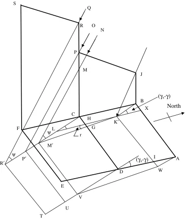
The area of saline water receiving solar radiation directly and the total projected area of the walls are computed from the solar altitude and azimuth angles, and latitude and
calculated according to Duffie and Beckman [12]. The area of water receiving solar radiation directly, and projected areas of the back, eastern side, west and front condenser walls are calculated by using the geometrical analysis of Fig.2. The area of water receiving solar radiation directly (Asb) is computed as follows:
Area of rectangle AIK′X, A1 =
(
)
(
)
ψ γ γ ψ γ γ tan cos tan sin 1 − −
− fe s fe s
b
Z Z
L (43)
Area of rectangle BCHX, A2 =
(
)
ψ γ γ tan cos1 fe s −
b Z
B
(44)
Area of triangle GHK′, A3 =
(
)
r Z
Bb fe s tan
tan cos 5 . 0 2 1 − − ψ γ γ (45)
(
)
(
)
(
)
(
)
(
)
(
)
[
]
0.51 2
2
1tan 2 tan cos
sin sin γ γ ψ ψ γ γ − − + − + − − = s fe bw b fe bw b s fe bw Z Z B Z Z B Z Z
r (46)
Asb=LblBbl – (A1+A2+A3) (47)
The projected areas of the back wall of the evaporator chamber and front wall of the condenser chamber are calculated from [25]:
(
)
ψ γ γ tan cos 1 − =′ b bw s
bw
Z L
A (48)
(
)
ψ γ γ tan cos 1 − =′ b fc s
fc
Z L
A (49)
of solar energy on the east and west walls is reversed. In view of the symmetry about solar noon, the projected areas of the two walls are given by:
(
)
< ≥ + − = ′ 0 , 0 0 , sin 5 . 0 tan sinAew 1
ω ω ψ γ γ r y Z
Bb fe s
(50)
(
)
> ≤ + − = ′ 0 , 0 0 , sin 5 . 0 tan sinAww 1
ω ω ψ γ γ r y Z
Bb fe s
(51)
(
)
5 . 0 1 2 2 1 cos tan tan 2 tan tan y − − + − += γ γ
ψ ψ ψ ψ s fe bw b fe bw b Z Z B Z Z
B (52)
In addition, hourly ambient air temperature was estimated from daily minimum and maximum ambient temperatures [26]. Similar equations were used to compute the effective solar irradiance in the CSS, with Zfc=0.
4. Results
41 Irradiance and temperature variation
Fig.4 shows the variation of observed and effective global irradiance with time. It is seen that the observed irradiance is higher than the effective irradiance in both the CSS and PSS, probably because some of the solar radiation intercepted by the glass cover does not reach the surface of saline water. Nevertheless, the effective irradiance in the PSS is slightly higher than that in the CSS, maybe due to the contribution of solar energy from the front wall of the condenser chamber for the PSS. Moreover, solar radiation is the most influential environmental parameter in distillate productivity [28]. These observations indicate that the direct use of Ggh in the heat balance equations would lead to overestimation of the distillate yield.
Fig.5 shows the variation of the temperature of the ambient air (Ta), glass cover (Tgc), and water in basins 1 (Twl), 2 (Tw2) and 3 (Tw3) at reference values of the design, operating and meteorological parameters. It is observed that all the temperatures conform to the variation in irradiance on the sample day. The values of Tgc for the CSS are higher than those of the PSS. At 12:00 h, the temperature difference (Twl-Tgc) is 9 and 14 K for the CSS and PSS respectively. This is probably due to heat flow from the evaporator basin into the condenser chamber which tends to lower the glazing temperature, thereby increasing (Twl-Tgc) in the PSS.
still, heat is lost to ambient environment through the glass cover, bottom and side walls while heat is transferred by purging (predominantly) and diffusion from the evaporator basin to the condenser unit of the PSS, in addition to heat loses through the glass cover, bottom and side walls. It is nevertheless pleasing to note that the values of Twl are comparable with experimental data reported in literature [11, 29].
It is also seen that the temperature of water (Tw2) in basin 2 (second effect) is below that of basin 1 of the present solar still from morning 8:00 h to around 17:00 h). This indicates that water vapor from the evaporator is able to condense on the underside of the basin 2 during the most part of the day, thereby augmenting the rate of productivity. After sunset, the temperature of the water in the basin 2 is higher than that of basin 1 probably due to lower rate of top heat loss from basin 3 than that from the glazing cover. The latter component of the solar still loses heat to environment through convection and radiation while water in the upper basin loses heat to the condenser cover which has an insulation shield over it. So, top heat loss from the condenser cover is predominantly by natural convection which would account for the lower rate of cooling in basins 2 and 3.
The temperature of water in basin 3 (Tw3) is lower than that of water in basin 2 (Tw2) of the PSS from 9:00 h to later than 24:00 h, which again shows that vapor from water in basin 2 would be able to condense on the underside of basin 3 during the most part of the day. In addition, Tw3 is higher than Ta from 11:00 h until after 24:00 h, which also indicates that distillate production would take place from the third effect during this period.
4.2 Distillate productivity
(third effect). Fig.6 shows the variation of cumulative distillate productivity of the CSS and PSS at reference values of the design, operating and meteorological parameters. It is seen that in the morning (up to about 10:00 h), the distillate productivity is extremely low for both stills. This is expected because production starts when air inside the still is saturated with water vapor. From about 10:00 h, the productivity of the CSS is lower than that of the PSS. At 24:00 h, the cumulative productivity of the CSS is 3.754 kg m-2 (with η=32 %) while that of the PSS is 6.080 kg m-2 (with η= 52 % and an improvement of 62 %). It should also be noted that there is insignificant production after 24:00 h. For the PSS, distillate contributions from the first, second and third effects are 60, 22 and 18 %
respectively. Purging contributes 97 % the water vapor that condenses on the under side of the upper basin while diffusion accounts for the remaining proportion. The daily
productivity of a CSS is about 3-4 kg m-2, with a maximum thermal efficiency of 35 % [2, 30], which agree with the present observations. Results for the PSS also conform very well to experimental findings of El-Bahi and Inan [5] and Fath and Elsherbiny [9].
4.3 Sensitivity analysis
other black thin film used) on the inner surface to enhance absorption of incoming solar radiation, which increases the water temperature and distillate yield.
Fig.8 shows the effect of the ratio (R) of the volume of the evaporator chamber to that of the condenser chamber. It is observed that the distillate productivity decreases with
increasing values of R. This observation is attributed to the fact that the pressure of air increases with decreasing volume. So, as the volume of the evaporator decreases, the pressure in the evaporator also increases, which results in an increase in purging from the evaporator chamber into the condenser chamber. These results are consistent with findings of Fath [10].
The effect of the mass of water in the first (mwl), second (mw2) and third (mw3) basins on the distillate productivity are presented in Fig.9. Productivity decreases by 0.980 kg m-2 when mwl is increased from 10 to 30 kg, probably due to an increase in the thermal mass of water which results in low temperatures being attained by the water (for the same amount of solar radiation intercepted by the system).These results conform to well-known previous findings on the effect of mwl on distillate productivity. Productivity decreases by 0.612 kg m-2 when mw2 is increased from 10 to 30 kg, and by 0.144 kg m-2 when mw3 is increased from 10 to 30 kg. It is observed that the effect of mw2 on productivity is more significant than that of mw3.
masses (mwl) less than 45 kg m-2. Our present findings are therefore reasonable because mwl=20 kg m-2.
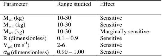
A summary of the sensitivity analysis is presented in Table 2. It is observed that the PSS is sensitive to absorptance of the evaporator basin liner (αbl), ratio of the evaporator to condenser chamber volumes (R), mass of water in the evaporator basin (mwl), mass of water in the middle basin (mw2) and wind velocity (Vwd). However, the mass of water in the upper basin (mw3) marginally affects the performance of the still.
4.4 Model performance
Simulation results show that the temperatures of the various still components are high during day time and low at night or during periods of low irradiance, which is expected in reality. In addition, the range of values of temperature is consistent with experimental results reported in literature. It is also observed that the levels of distilled water produced by the two solar stills also compare favorably with findings from previous studies. It appears therefore that the performance of our model is satisfactory.
5. Conclusion
A passive solar still with separate condenser has been studied theoretically. The system has one basin in the evaporation chamber (basin 1) and two basins (2 and 3) in the
compared with that of a conventional solar still under the same meteorological conditions. Results show that the distillate yield of the present still is higher than that of the
conventional type under the same meteorological conditions. Purging is the most
significant mode of vapor transfer from the evaporator into the condenser chamber, while the first effect contributes the highest proportion to the total distillate yield. It is also found that the productivity of the solar still with separate condenser is most sensitive to the absorptance of the evaporator basin liner, mass of water in basins 1 and 2, and wind velocity. The mass of water in basin 3 has a marginal effect on distillate production. The performance of the present solar still is satisfactory.
Nomenclature
A area (m2)
Aec area across the entrance from the evaporator to condenser chamber (m2) A′ projected area (m2)
B width (m)
Cp specific heat capacity at constant pressure (J kg-1 K-1) CSS conventional solar still
D coefficient of diffusion mass transfer of water vapor in air (=2.56x10⁻⁵ m2 s-1) g acceleration due to gravity (m s-2)
F solar radiation absorption factor (dimensionless) G irradiance (Wm-2)
k thermal conductivity (W m-1 K-1) L length (m)
m mass (kg)
m rate of mass flow (kg s-1)
Nu Nusselt number (dimensionless) P pressure (N m-2)
PSS present solar still
Pr Prandtl number (dimensionless) Q heat flux (W m-2)
R ratio of evaporator chamber volume to condenser chamber volume (dimensionless) Ra Rayleigh number (dimensionless)
Rv vapour gas constant (J kg-1K-1) S channel or equivalent spacing (m) t time (s)
T temperature (K)
U coefficient of heat loss (W m-2 K-1) V velocity (m s-1)
x thickness (m)
xec gap crossed by water vapour from evaporator to condenser shown in Fig. (1), (m) Z height (m)
Greek symbols
α′ thermal diffusivity (m2 s-1) β angle of inclination (degree)
β′ coefficient thermal expansivity (K-1)
γ surface azimuth angle measured from the south (degree) γs solar azimuth angle measured from the south (degree) ∆ change in
η system efficiency (%) ρ reflectance (dimensionless) τ transmittance (dimensionless) ϕ density (kg m-3)
σ Stefan-Boltzman constant (W m-2 K-1) ε emittance (dimensionless)
ν kinematic viscosity (m2 s-1) ω hour angle (degree)
Subscripts
1 initial/first 2 final/second a air/ambient
bl-wl from basin liner 1 to water in basin 1 b2-w2 from basin liner 2 to water in basin 2 bo bottom
b3-w3 from basin liner 3 to water in basin3 c convective
co condensing cover
cs condensing surface (glass cover, upper basin liner and condensing cover) d diffusion
dw distilled water e evaporative ef effective
ew eastern side wall
fc front wall of the condenser chamber fe front wall of the evaporator chamber gc glass cover
gc-a from glass cover to ambient air gc-sk from glass cover to sky
gh global on horizontal surface iw internal part of the wall pu purging
r radiative sb still base sk sky
sw side wall
vc vapor in condenser chamber ve vapor in evaporator chamber w water
wd wind
wl-gc from water in basin 1 to glass cover w2-b3 from water in basin 2 to basin liner 3
w3-co from water in upper basin to condenser cover ww western side wall
Acknowledgements
The authors are very grateful to the Commonwealth Scholarship Commission for the financial support. The Centre for WASHTED at the Malawi Polytechnic, and Universities of Strathclyde and Malawi are also acknowledged for the various forms of support.
References
[1] Abu-Qudias M, Bassam A, Abu-Hijleh K, Othman ON. Experimental study and Numerical simulation of a solar still using an external condenser. Energy 1996; 21: 851-855.
[2] Al-Kharabsheh S, Goswami DY. Experimental study of an innovative solar water desalination system utilizing a passive vacuum technique. Solar Energy 2003; 75: 395-401.
various absorber materials and solar collector integration. Renewable Energy 1996; 9:758-61.
[4] Akash BA, Mohsen MS, Osta O, Elayan Y. Experimental evaluation of a single-basin solar still using different absorbing materials. Renewable Energy 1998; 14: 307-310.
[5] El-Bahi A, Inan D. Analysis of a parallel double glass solar still with separate condenser. Renewable Energy 1999; 17:509-21.
[6] Bassam A, Hijleh KA, Rabab’h HM. Experimental study of a solar still with sponge cubes in basin. Energy conversion and Management 2003; 44:1411-1418.
[7] Abdel-Rehim ZS, Lasheen A. Improving the performance of solar desalination systems. Renewable Energy 2005; 30:1955-71.
[8] Tiwari GN, Singh HN, Tripathi R. Present status of solar distillation. Solar Energy 2003; 75:367-73.
[9] Fath HES, Elsherbiny SM. Effect of adding a passive condenser on solar still performance. Energy Conversion and Management 1993; 34:63-72.
[10] Fath HES. High performance of a simple design, two effect solar distillation unit. Desalination 1996; 107:223-33.
[11] El-Bahi A, Inan D. A solar still with minimum inclination, coupled to an outside condenser. Desalination 1999; 123:79-83.
[12] Duffie JA, Beckman WA. Solar Engineering of Thermal Processes, 2nd ed. New York:Wiley Interscience, 1991.
100:99-104.
[14] ASHRAE. Fundamentals Handbook. Atlanta:American Society of Heating, Refrigerating And Air-Conditioning Engineers, 2001.
[15] IAPWS. The IAPWS Formulation 1995 for the thermodynamic properties of ordinary water substance for general and scientific use. International Association for the Properties of Water and Steam, 1996.
[16] Wattmuf JH, Charters WWS, Proctor D. Solar and wind induced external coefficients for solar collectors. Compless 1977; 2:56.
[17] Sharma VB, Mullick SC. Estimation of heat-transfer coefficients, the upward heat flow, and evaporation in a solar still. ASME Journal of Solar Engineering 1991; 113:36-41.
[18] Dunkle RV. Solar water distillation: the roof type still and a multiple effect diffusion still. International Development in Heat Transfer. International Heat Transfer Conference, University of Colorado 1961, pp.895-902 (part 5).
[19] Incropera FP, Dewitt DP. Fundamentals of heat and mass transfer, 5th ed. New York: John Wiley & Sons, 2002.
[20] Mowla D, Karimi G. Mathematical modeling of solar stills in Iran. Solar Energy 1995; 55:389-393.
[22] Tripathti R, Tiwari G.N. Thermal modeling of passive and active solar stills for
different depths of water by using the concept of solar fraction. Solar Energy 2006; 80:956-967.
[23] Diabate´ L, Blanc Ph, Wald L. Solar climate in Africa. Solar Energy 2004; 76: 733–744.
[24] Madhlopa A. Solar radiation climate in Malawi. Solar Energy 2006; 80:1055-7. [25] Tripathi R, Tiwari GN. Performance evaluation of solar still by using the
concept of solar fraction. Desalination 2004; 169:69-80.
[26] Muneer T. Solar radiation & daylight models for the energy efficient design of buildings. Oxford: Reed Educational and Professional Publishing Ltd ; 1997, chapt.7.
[27] Burden RL, Faires JD. Numerical Analysis, 3rd ed. Boston: PWS Publishers; 1985, chapt. 8.
[ 28] Nafey AS, Abdelkader M, Abdelmotalip A, Mabrouk AA. Parameters
affecting solar still productivity. Energy Conversion and Management 2000; 41: 1797-1809.
[29] Porta MA, Chargy N, Fernández JL. Extreme operating conditions in shallow still. Solar
Energy 1997; 61:279-86.
[30] Kalogirou S. Survey of solar desalination systems and system selection. Energy 1997; 22:69-81.
(a)
Condensing cover Glass cover
Solar radiation shield
Water in basin 1
Water in basin 3
Condenser Evaporator
xec
Water basin 2 4 x distillate
channel
Insulation 1
Insulation 2
Front wall of condenser chamber
Back wall of evaporator chamber Air channel
ρgc
ρwlτgc (1+ρfc+ρwi)
τgc ρwiτgc
ρfcτgc τgc Sun
(b)
Fig. 1: A cross-section of the present solar still, showing a) the evaporator and condenser units, and b) distribution of solar radiation inside the solar still.
North
W
T P′
R′
U
ψ
P
M′ ψ
H
I L
V
D
A B
C
G
K′
J
(γs-γ)
(γs-γ)
X
r
N Q
R
F
E S
Fig.2: Geometry of the solar still and rays from the sun: ABFE= area of rectangular base of the still, ABCD=area of evaporator basin, BJPC=area of eastern side wall of the evaporator chamber, CFSR=area of eastern side wall of condenser chamber, AB=length of the evaporator basin (Lbl), AD= width of the evaporator basin (Bbl), LK′ is equal and parallel to BC, WK′ is equal and parallel to AB, BK′ is parallel and equal to CL, CM=height of back wall (Zbw), angle BK′J=ψ, angle CLH=(γs-γ), BJ=height of front wall of evaporator basin (Zfe), PR=height of the front wall of the condenser (Zfc), CDVM′=projected area of the back wall, ADVW =projected area of west, TR′P′U=projected area of the front wall of the condenser chamber, DGK′I=area of water receiving solar radiation directly, and KK′, NM′, OP′and QR′ are sun rays projected on the still base.
Yes
No
Guess initial values of temperatures of glass cover (Tgc), saline water (Twl, Twm & Twu), basin liner (Tbl) and distillate yield (=0, initially)
Start
Compute temperature dependent physical properties of fluids
Calculate the various coefficients of heat transfer
Commence solving the heat balance equations iteratively to obtain new temperatures
Compute solar altitude (ψ) and azimuth (γs) angles
Calculate the area of water receiving solar radiation directly and the projected areas of the back, east and west walls of the evaporator chamber and the front wall of the condenser chamber
Compute the effective solar energy using the appropriate areas
Compute distillate yield in the time step, using new temperatures, then add it to the initial value. Solution converges No Replace initial
temperatures with new ones
Fig.3: Flow chart for computation of the effective irradiance, temperatures of system components and distillate yield in MATLAB.
0 200 400 600 800 1000 1200
5 6 7 8 9 10 11 12 13 14 15 16 17 18
Local time (h)
Ir
ra
d
ia
n
c
e
(
W
m
-2 )
observed effecive_CSS effective_PSS
280 290 300 310 320 330 340 350
6 8 10 12 14 16 18 20 22 24
Local time (h)
T
e
m
p
e
ra
tu
re
(
K
)
Ta Tgc-CSS Twl-CSS Tgc-PSS Twl-PSS Twm Twu
0 1 2 3 4 5 6 7
6 8 10 12 14 16 18 20 22 24
Local time (h)
C
u
m
u
la
tiv
e
d
is
til
la
te
y
ie
ld
(
k
g
m
-2 )
CSS
PSS
0 1 2 3 4 5 6 7
6 8 10 12 14 16 18 20 22 24
Local time (h)
C
u
m
u
la
ti
v
e
d
is
ti
lla
te
y
ie
ld
(
k
g
m
-2 )
absorptance=0.90 absorptance=0.95 absorptance=1.00
0 1 2 3 4 5 6 7
6 8 10 12 14 16 18 20 22 24
Local time (h)
C
u
m
u
la
ti
v
e
d
is
ti
lla
te
y
ie
ld
(
k
g
m
-2 )
R=0.1 R=0.5 R=0.9
0 1 2 3 4 5 6 7
6 8 10 12 14 16 18 20 22 24
Local time (h)
C u m u la ti v e d is ti lla te y ie ld ( k g m -2 ) mwl=10 kg mwl=20 kg mwl=30 kg (a) 0 1 2 3 4 5 6 7
6 8 10 12 14 16 18 20 22 24
Local time (h)
0 1 2 3 4 5 6 7
6 8 10 12 14 16 18 20 22 24
Local time (h)
C
u
m
u
la
ti
v
e
d
is
ti
lla
te
y
ie
ld
(
k
g
m
-2 )
mwu=10 kg mwu=20 kg mwu=30 kg
(c)
0 1 2 3 4 5 6 7
6 8 10 12 14 16 18 20 22 24
Local time (h)
C
u
m
u
la
ti
v
e
d
is
ti
lla
te
y
ie
ld
(
k
g
m
-2 )
Vwd=2 m/s Vwd=4 m/s Vwd=6 m/s
Table1: Reference design, operational and meteorological parameters for the conventional still (CSS) and present still (PSS).
Parameters CSS PSS
Design parameters
Abl (m2) 1.000 1.000
Abu (m2) 1.015
Asc (m2) 0.05
Aev (m 2
) 1.262 2.606
Asm (m 2
) 1.294
Asu (m2) 0.800
k1 (W m-1 K-1) 0.0346 0.0346 k2 (W m
-1
K-1) 0.1200 0.1200
mbl (kg) 5.0 5.0
mbu (kg) 6.0
Mbm (kg) 6.0
mgc (kg) 10 10
R (dimensionless) 0.5
x1 (m) 0.020 0.020
x2 (m) 0.023 0.023
xec (m) 0.02
Zbw 0.468 0.418
Zfc 0.632
Zfe 0.238 0.238
αbl (dimensionless) 0.95 0.95
βco (degree) 10
βgc (degree) 16 16
Operational parameters
mwl (kg) 20 20
mwm (kg) 10 10
mwu (kg) 10 10
Meteorological parameters Vwd (m s
-1
Table 2: Summary of the results of the effects of various parameters on distillate production.
Parameter Range studied Effect
Mwl (kg) 10-30 Sensitive
Mwm (kg) 10-30 Sensitive
Mwu (kg) 10-30 Marginally sensitive
R (dimensionless) 0.1 – 0.9 Sensitive
Vwd (m s-1) 2-6 Sensitive