Rochester Institute of Technology
RIT Scholar Works
Theses Thesis/Dissertation Collections
2008
Cognitive dimensions usability assessment of
textual and visual VHDL environments
George Kontos
Follow this and additional works at:http://scholarworks.rit.edu/theses
This Master's Project is brought to you for free and open access by the Thesis/Dissertation Collections at RIT Scholar Works. It has been accepted for inclusion in Theses by an authorized administrator of RIT Scholar Works. For more information, please [email protected].
Recommended Citation
Cognitive dimensions usability assessment of
textual and visual VHDL environments
(What can it tell us about visual programming language usability?)
Masters Project
George C. Kontos
Rochester Institute of Technology
Golisano College of Computing & Information Sciences Department of Computer Science
102 Lomb Memorial Drive Rochester, NY 14623-5608
Abstract
Visual programming languages promise to make programming easier with simpler graphical methods, broadening access to computing by lessening the need for would-be users to become proficient with textual programming languages, with their somewhat arcane grammars and methods removed from the problem space of the user. However, after more than forty years of research in the field, visual methods remain in the margins of use and programming remains the bailiwick of people devoted to the endeavor. VPL designers need to understand the mechanisms of usability that pertain to complex systems like programming language environments.
Effective research tools for studying usability, and sufficiently constrained, mature subjects for investigation are scarce. This study applies a usability research tool, with its origins in applied psychology, to a programming language surrogate from the hardware description language class of notations. The substitution is reasonable because of the great similarity between hardware description languages and programming languages. Considering VHDL (the VHSIC Hardware Description Language) is especially worthwhile for several reasons, but primarily because significant numbers of digital designers regularly employ both textual and visual VHDL environments to meet the same real-world design challenges.
Contents
1 Introduction...7
1.1 Problem statement...8
1.2 Hypothesis...8
1.3 Previous work ...8
1.4 New work...9
1.5 Document Structure ...9
2 The cognitive dimensions framework...11
2.1 Overview of the cognitive dimensions framework...12
2.2 Cognitive dimensions framework concepts and theory ...16
2.3 Application of the cognitive dimensions framework...23
2.4 Limitations and pitfalls in using the cognitive dimensions framework...29
2.5 Use of the cognitive dimensions framework in this study...29
3 Hardware description languages and VHDL ...33
3.1 Hardware description languages and programming languages ...33
3.2 VHDL Overview...37
4 Analysis method...51
4.1 Method ...52
4.2 The benchmark design ...52
4.3 Cognitive dimensions walkthrough assessments ...52
4.4 Usability requirements ...53
4.5 Visualizing the results...53
4.6 Comparative analysis ...54
5 Results and analysis ...57
5.1 Usability requirements for digital system design...57
5.2 Cognitive dimensions walk-through assessments...58
5.3 Comparison of visual and textual VHDL cognitive dimensions profiles ...74
5.4 What the usability evaluation says about visual methods...76
5.5 Use of the cognitive dimensions framework ...78
5.6 Recommendations for further study...79
6 Glossary ...81
The real romance is out ahead and yet to come. The computer revolution hasn't started yet. Don't be misled by the enormous flow of money into bad de facto standards for unsophisticated buyers using poor adaptations of incomplete ideas.
– Alan Kay
1 Introduction
Advocates of visual programming languages promised VPLs would make programming easier with simpler graphical methods, broadening access to computing by lessening the need for would-be users to become proficient with textual programming languages, with their somewhat arcane grammars and methods removed from the problem space of the user. This might lead to an era of increased computer literacy where even children would design their own applications. Why pay $600 for Photoshop? Simply, design orsketch your own photo-processor. After more than forty years of research in the field, however, visual methods remain in the margins of use and programming remains the work of people devoted to the art. It has become clear that usability is a complex issue, beyond the mere inclusion of visual methods to describe and understand programs. Visual programming language designers need to understand the mechanisms of usability that pertain to complex systems like programming language environments, even to realize modest improvements.
So, what, exactly, are visual programming languages? Burnett, et al (1995) offer the view that VPLs are simply languages that use some type of visual representations to achieve what would otherwise be accomplished using text in conventional programming languages. Burnett and others have developed detailed taxonomies of VPLs;
Boshernitsan and Downes suggest the two most significant classifications are purely visual languages and hybrid text and visual systems.
Where did VPLs come from? Boshernitsan and Downes (Boshernitsan & Downes, 1997) attribute the multidisciplinary origins of visual programming to work in the fields of computer graphics, programming languages and human-computer interaction.
Boshernitsan and Downes cite several milestone developments: (1) Ivan Sutherland’s Sketchpad designed in 1963, [2] a graphical dataflow language, designed in 1965 by Ivan Sutherland’s brother, William Sutherland, and [3] David Canfield Smith’s PhD
dissertation, “Pygmalion: A Creative Programming Environment” published in 1975. Some consider Sketchpad, which ran on a TX-2 computer at MIT, the first CG application. It allowed users, with a light pen, to create 2D graphics from simple primitive geometries. William Sutherland’s dataflow language enabled users to create, execute and debug dataflow diagrams within a visual environment. Smith’s Pygmalion introduced two new concepts: programming by demonstration and icons.
including: Why do we continue to program computers textually? Would programmers be more productive if they could use graphical methods? In addition, wouldn't more people be able to program, if they could employ the same visual representations they naturally use when they consider problems and their solutions?
Advocates of VPLs respond positively to the previously mentioned questions. Critics within the computer science community, however, citing a lack of empirical evidence supporting the claims of proponents, and the problem of scalability, have tended to dismiss the significance of VPLs. Whitely [7] addresses the question of empirical
evidence for and against. Burnett [4] characterizes the problem of scaling-up, i.e., making VPLs suitable for large-scale programming problems without increasing complexity, and thereby countering the simplifications gained from the use of visual methods.
1.1 Problem statement
Visual programming language’s promise of easier more accessible programming environments has not come to fruition after 40 years of research and development in academia and business. Primary problems include usability (Green & Petre, Usability analysis of visual programming environments: a cognitive dimensions framework, 1996), scalability (Burnett, Baker, Bohus, Carlson, Yang, & Zee, 1995) and the lack of theory and experimental methods to guide design (Whitley, 1997).
1.2 Hypothesis
This project stems from the hypothesis that application of the cognitive dimensions framework to textual and visual VHDL design language environments will highlight usability issues that hamper visual programming language environments.
Furthermore, because both textual and visual VHDL environments have significant numbers of users, understanding gained from this study may produce verifiable
predictions that can serve as a basis for future experiments, as well as for formalization of the cognitive dimensions of notations as a theory.
1.3 Previous work
1.4 New work
This study involves several components. Preliminary work included the investigation of the cognitive dimensions framework and hardware description languages. The study established the suitability of the cognitive dimensions framework for evaluating the usability of computer languages, and the viability of hardware description language as surrogates for programming language research. These components of the study are complete and reflected in the document as it stands today as a proposal.
The remainder of the work involves the cognitive dimensions usability assessment of the hardware description language, VHDL. To assess the usability impact of visual methods, the study will develop and compare the usability profiles of much used textual and much used graphical VHDL environments and attempt to relate usability differences to visual methods.
1.5 Document Structure
This document is the final report for a Masters project in computer science. The report (1) describes the cognitive dimensions framework for assessing the usability of notational systems such as programming language environments; (2) introduces hardware
description languages and provides the rationale for considering them in this context; and (3) presents the analysis method and (4) reports and interprets results. The overall
document structure follows.
Document
sections
Section 1, Introduction...7
Section 2, The cognitive dimensions framework...11
Section 3, Hardware description languages ...33
Section 4, Analysis method...51
2 The cognitive dimensions framework
Thomas Green, working from the perspective of applied psychology and seeking an alternative to more detailed human computer interaction (HCI) techniques, introduced the cognitive dimensions of notations, in 1989 (Green, 1989) as a framework for
characterizing the usability of notational systems such as programming languages. Blackwell (2006) notes that since then, researchers have published over 50 papers on related topics. These include a cognitive dimensions usability study of visual
programming languages (Green & Petre, 1996), and a cognitive dimensions tutorial for designers (Green & Blackwell, 1998). Many of the subsequent publications, including Green’s own, refer more succinctly to the cognitive dimensions framework’, or the CDs framework.
This section lays down the groundwork for using the CDs framework. It includes an overview that provides a high-level description and covers the framework’s development history and aims. The remainder of the section deals with theory, application, limitations and the approach taken in this study. The section’s structure is as follows.
Section
2
content
2.1 Overview of the cognitive dimensions framework...12
2.1.1 The cognitive dimensions framework in a nutshell ...12
2.1.2 History ...14
2.1.3 Aims...15
2.2 Cognitive dimensions framework concepts and theory ...16
2.2.1 The actors...17
2.2.2 The activities...19
2.2.3 Requirements for usability...21
2.3 Application of the cognitive dimensions framework...23
2.3.1 What the CDs framework delivers...23
2.3.2 Green and Petre’s VPL usability evaluation...24
2.3.3 Green and Hendry’s spreadsheet usability evaluation ...25
2.3.4 Microsoft’s Visual Studio API usability evaluation ...28
2.4 Limitations and pitfalls in using the cognitive dimensions framework...29
2.1 Overview of the cognitive dimensions framework
Alan Blackwell’s Cognitive Dimensions of Notations Resource Site (Blackwell, 2007) offers the following as an introduction.
The Cognitive Dimensions of Notations (CDs) framework is an approach to analyzing the usability of information artefacts: these are often software systems, but also include many other things that people interact with, including those made out of plastic and paper. CDs can be applied to discover useful things about usability problems that are not easily analysed using conventional techniques from Ergonomics or Human Computer
Interaction. They are being used by many researchers around the world, and in the last few years they are also being adopted by commercial product designers.
2.1.1 The cognitive dimensions framework in a nutshell
The cognitive dimensions framework is both a research tool and a design tool for describing the usability of notational systems and information artifacts. Examples of notational systems include programming language environments, computer-aided design tools and music notation. Examples of information artifacts include items such as pagers, cell phones, personal data assistants (PDAs) and frames (devices for displaying digital images).
Table 1. Comparison of cognitive dimensions and traditional evaluative approaches.
Cognitive Dimensions Traditional Approaches
Broad-brush Highly detailed
Quick to learn Specialist training needed
Quick to apply Lengthy analysis
Applicable at any stage of
design Requires full task analysis (GOMS/KLM) or fully implemented design or mock-up (heuristic evaluation)
Differentiates user activity Types all activity evaluated identically
Multi-dimensional Single dimension
Vague Precise metric
Comprehensible to
non-specialists Only the metric is comprehensible - not the basis for it
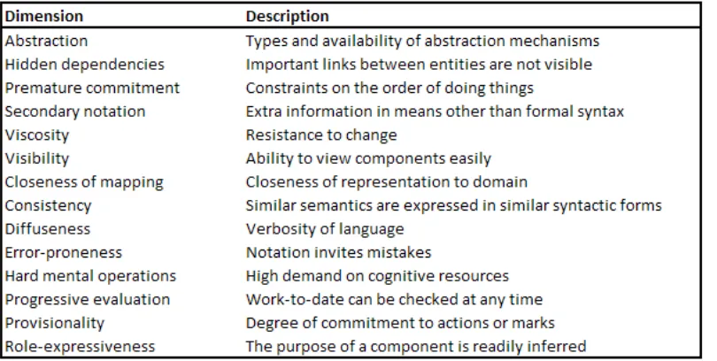
The CDs tutorial lists thirteen, or so, cognitive dimensions. Table 2 lists them and provides brief descriptions. Several of the references cited herein provide fuller
[image:14.612.96.501.445.649.2]descriptions; these include (Green, Cognitive dimensions of notations, 1989), (Green & Petre, 1996), (Hendry & Green, 1994) and (Green & Blackwell, 1998). Green and Blackwell describe the dimensions as lexicalizations (realizations of conceptual meaning in single words) and suggest that lexicalization is essential for serious thought and discussion so that recurrent concepts do not need repeated explanation and interpretation every time they arise.
Table 2. The cognitive dimensions (Green & Blackwell, 1998).
provide names, at least in a notional sense. However, without the lexicalizations, full consideration and appreciation of the concepts may be difficult. Petre (2006) relates the following illustrative anecdote from her observations of professional programmers. …one team, when introduced to the notion of ‘viscosity’, responded: ‘‘Oh, so that’s what it’s called’’. A week later, the term ‘viscosity’ had been adopted seamlessly into the team’s vocabulary. Moreover, they lost no time in explaining to us that, although low viscosity was usually desirable, there came a point in a project when the major design decisions were made, and where one wanted the design and its representation to stabilize. At that point—which they termed “the congealing point”—the developers wanted the representation to resist change, to increase in viscosity.
Developers of information artifacts and notational systems such as programming
language environments, with a relatively small investment of time, can apply the CDs in order to assess the system’s suitability for a given use or to evaluate the impact of design decisions on usability. Evaluators assess the suitability of the information artifact or notational system for specific types of cognitive activity along each of the different dimensions. The result is a profile that characterizes the usability of the artifact or system for the various cognitive tasks.
2.1.2 History
Thomas Green first developed CDs to analyze the relationships between programmers’ cognitive strategies and the information structures within programming languages (Dagit, Lawrance, Neumann, Burnett, Metoyer, & Adams, 2006). The 1989 paper (Green,
Cognitive dimensions of notations, 1989) established several of the CDs, but the framework gained more widespread acceptance as an analytical tool seven years later when Green and Marian Petre applied a refined and augmented set of cognitive
dimensions to their usability analysis of visual programming languages (Green & Petre, Usability analysis of visual programming environments: a cognitive dimensions
framework, 1996).
and, on the research it has generated. They also offer recommendations for future development and applications of the CDs.
2.1.3 Aims
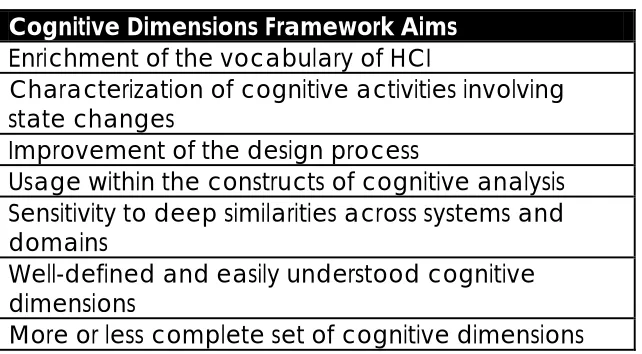
[image:16.612.148.469.258.435.2]Green’s original intention was to improve the design process by making it easier to talk about design usability, at an appropriate level of abstraction (Green, Blandford, Church, Roast, & Clarke, 2006). Green discusses specific aims for the CDs framework in his two contributions to the 2006 special edition of the JVLC (Green, Aims, achievements, agenda—where CDs stand now, 2006) (Green, Blandford, Church, Roast, & Clarke, 2006).
Table 3. Summary of CDs framework development aims.
Cognitive Dimensions Framework Aims
Enrichment of the vocabulary of HCI
Characterization of cognitive activities involving state changes
Improvement of the design process
Usage within the constructs of cognitive analysis Sensitivity to deep similarities across systems and domains
Well-defined and easily understood cognitive dimensions
More or less complete set of cognitive dimensions
Table 3 enumerates the objectives as Green recalled them, five stated and tow unstated. The first stated objective was to facilitate thinking about and discussing recurrent concepts relevant to the usability of programming languages and other information artifacts by enrichment of the HCI vocabulary. They also wanted the CDs to be able to handle activities that involved a change of state. At the time, HCI focused on such things as menu layout, button size and other details. These were handy tools for evaluating GUIs but not problems like having to remake a table of contents if font changes moved text to different pages. Another goal was to develop an approach that was design centric. Noting that design activity involves frequent plan changes, they wanted to know what
characteristics of devices made them good design tools. Petre (Petre, 2006) put it this way: “What we both wanted to know was how notations (or, more broadly, information artefacts) work when they do, and why they don’t when they fail. CDs were an attempt to capture and articulate these issues.” A fourth stated objective was that CDs assessments would be the result of cognitive analyses of user activities. The final stated aim of the developers of the framework was to develop an approach that would reveal significant similarities in different notational systems across a range of domains.
definition of the baseline dimensions has, in fact, remained stable; their definitions easy to understand. Users applying the dimensions in different domains sometimes find it necessary to modify existing and develop new dimensions.
Alan Blackwell, Green’s student at the time Green and Petre were working on the VPL analysis, provides an expanded perspective on the goals (Blackwell, et al., 2001). Designers use cognitive technologies to develop tools to transfer information from the mind to the physical environment in order to offload it from short-term memory and interact with it. Examples range from paper with visible markings to programming language environments. Developers of new cognitive technologies often encounter the same problems repeatedly when designing different systems. Expert designers eventually, and with luck, produce well-designed tools, suitable for their users’ activities. However, not all designers are expert at anticipating and providing for the needs of users. Computer scientists and engineers, for example, may understand their own technical problems better than they understand the problems of the user. Green and his team of CDs framework developers believed that providing a vocabulary for identifying and
discussing design decision implications on usability would result in improved designs. They also believed such a vocabulary should draw from the field of cognitive psychology but, at the same time, remain easily understood by system designers.
2.2 Cognitive dimensions framework concepts and theory
Programming is, like other design tasks, a complex and creative activity that includes aspects of engineering, science and craft. Like other design tasks, programming requires research, planning, creative thought and analysis. Frequently, we rely on external
representations as aids to such activities. Programming environments provide the means to produce the final product of the design process, the program, but they also afford developers the ability to create and manipulate representations that support the process. Usability of the programming language is the degree to which it facilitates or hinders the user in achieving the eventual or intermediate objectives.
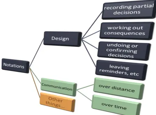
Table 4. Uses for notations
Thomas Green’s approach to studying the usability of programming languages was to identify and observe the actors and activities inherent to the design process. He then sought to discover and characterize the requirements necessary to specify the usability of a system for design (these are the dimensions). To do this he realized the need to augment the vocabulary of the field of human computer interaction. The result is the cognitive dimensions framework.
This section introduces the theoretical constructs upon which the CDs framework lies. It draws heavily from three sources (Green, Cognitive dimensions of notations, 1989), (Blackwell, et al., 2001) and (Green & Blackwell, Cognitive Dimensions of Information Artefacts: a tutorial, 1998).
2.2.1 The actors
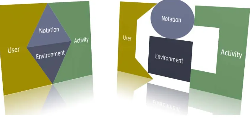
Figure 1. Usability occurs at the interfaces of the system; a poor fit between any system elements can cause usability problems.
2.2.1.1 Users
Different users have different needs. Users may be quite different: novice or expert, casual or deeply invested, well versed in the use metaphor, or not. Different types of users may have different usability requirements. Therefore, one should be cognizant of the user when considering system usability.
2.2.1.2 Notations
A notation is comprised of markings made within some medium. The markings may be visual, audible, and tactile or sensed in some other way. Examples include ink on paper, and patterns of raised dots read by touch. Multiple notations can exist within the same medium. (Blackwell, et al., 2001)
Green uses the term ‘notation’ to distinguish the form and structure of a language from its content and offers the following illustration. Some may criticize the programming
language, Pascal, for content issues such as poor string manipulation, bit processing, and file handling facilities. As a notation, however, these issues are not relevant. Pascal’s rigid identifier hierarchy, on the other hand, is a notational issue that may represent advantage or disadvantage depending on the circumstances of use. (Green, Cognitive dimensions of notations, 1989)
2.2.1.3 Notational System = Notation + Environment
Figure 2. A notational system is comprised of a notation and an environment for accessing and manipulating the notation. As the environment enables use of the notation, usability is only meaningful with respect to the system.
Green observed that even the simplest notations require environments for use and that a notational system is comprised of a notation and an environment, such as an editor, for manipulating that notation. By definition, one can only use a notation within a supporting environment, and, different environments will support a notation to varying degrees. In addition, as it turns out, the boundary between the notation and the environment is not always easy to draw. As an example, even a simple and familiar pencil and paper system has a notational component and an environmental component. In this case, the
environment has characteristics that present advantages over, say, computer-based environments, when it comes to such activities as reading large amounts of text, making quick edits and capturing hesitations and commitments.
The fundamental principle is that user behavior is a function of both the notation and the environment. Suitable systems, for a given activity, require that the environment supports the notation and vice versa. (Green, Cognitive dimensions of notations, 1989)
It also follows that the CDs, which describe usability, apply only to notational systems and information artifacts, and not to notations alone. Information artifacts are self-contained notational systems such as telephones, central heating controls, and other automated systems (Blackwell, et al., 2001).
2.2.2 The activities
indicates Green and Blackwell’s conclusions regarding the ideal profiles for several of the notational activities.
Table 5. Types of cognitive activities users perform with notational systems (Green & Blackwell, 1998) (Blackwell A. , Human Computer Interaction Notes, 2001)
Activity Description Examples
Search Finding information stored within the notational structure, using methods provided by the
environment
Finding a specific value in a spreadsheet
Incrementation Adding information to a notation without altering the notation’s structure
Adding a new card to a card file; adding a formula to a spreadsheet
Transcription Copying content from one
notation to another notation Copying book details to an index card; converting a formula into spreadsheet terms Modification Changing an existing
notational structure, without adding new content
Changing the index terms in a library catalogue; changing the layout of a spreadsheet;
modifying the spreadsheet to compute a different problem Exploratory
Design
Combining incrementation and modification, to
produce a result that is not known in advance
Typographic design; sketching; programming on the fly
(‘hacking’); digital system design
Table 6. Desired cognitive dimensions profiles by activity (Green & Blackwell, Cognitive Dimensions of Information Artefacts: a tutorial, 1998)
transcription incrementation modification exploration
viscosity acceptable acceptable harmful harmful
hidden dependencies acceptable acceptable harmful acceptable for small tasks
premature
commitment harmful harmful harmful harmful
abstraction barrier harmful harmful harmful harmful
2.2.3 Requirements for usability
The set of cognitive dimensions are the set of measures Green identified to allow for the specification and evaluation of system usability. From his observations of the design process, Green identified a set of relevant cognitive activities. The old view of design was that it proceeds in a top-down linear fashion from requirements definition, to
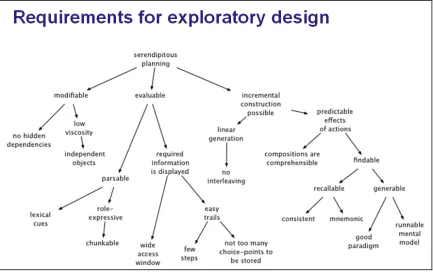
specification, to test, etc. This is naïve, as any designer knows, and as any project manager worth their salt, will admit. A more pessimistic view is that change occurs anywhere and at any time; that progress is made non-uniformly and that high-level and low-level decisions are under constant ‘attack’. With this more realistic, opportunistic view of the design process, Green indentified several implications (Figure 3), and eventually, the set of requirements for usability (Figure 4). The codification of these requirements resulted in the set of cognitive dimensions.
Figure 4. From the premise of opportunistic design, Green reasoned usability requirements for supporting systems (Green, End-User Development: Current Experiences and Future Challenges, 2003).
2.2.3.1 Cognitive dimensions
The dimensions are ‘cognitive’ because they characterize usability aspects that require mental, not physical, activity. For example, button size is a physical issue. The degree to which a system requires users to translate a conceptual operation into a number of discrete tasks is a cognitive issue. (Green & Blackwell, Cognitive Dimensions of Information Artefacts: a tutorial, 1998)
2.2.3.2 Cognitive dimensions
Green observed that physicists are able to state physical quantities in terms of
combinations of three fundamental dimensions, mass, length, and time, and envisioned a similarly elegant set of dimensions for use in the domain of HCI. He reasoned that we might be able to characterize computer use by the interrelationships between a single preferred cognitive strategy and a small number of facts about the language of communication, or ‘notation’, and the circumstances of its use, or ‘environment’. He concluded that the preferred cognitive strategy, at least when it comes to designing
independence, or at least ‘pairwise’ independence, is a loose assumption when using the set. (Green, Cognitive dimensions of notations, 1989)
2.2.3.2.1 Trade-offs and ‘pairwise’ independence
Since the cognitive dimensions are independent in theory, it should be possible to improve the design of a system so its value in one dimension changes without affecting values in other dimensions. In real systems, however, independence is typically
‘pairwise’. Two dimensions may be independent, but usually a change in one of an independent pair, will affect some other third dimension. Redesign is therefore, as usual, an exercise in choosing trade-offs and making compromises. This is like the relationship between the temperature, pressure and volume of gas. If one changes the temperature of a gas and maintains its volume, the pressure also changes. If one maintains the pressure, the volume must change. Therefore, although pressure, temperature, and volume are conceptually independent, for real systems they are only pairwise independent. (Green & Blackwell, Cognitive Dimensions of Information Artefacts: a tutorial, 1998).
2.2.3.2.2 Neutrality
The cognitive dimensions are neutral (i.e., neither good nor bad). To use another physics analogy, an object’s mass is a neutral property of that object. Depending on what use someone may have for the object, its mass may represent an advantage or a disadvantage. At least one of the CDs, however, seems to lack neutrality, if only in name. Who would care to design or use a system with a relatively high degree of error-proneness?
2.3 Application of the cognitive dimensions framework
This section describes what the CDs framework delivers and concludes with three examples of commercial and academic applications.
2.3.1 What the CDs framework delivers
Using the CDs approach produces a profile. Designers or assessors evaluate the
notational system or information artifact under consideration with respect to the cognitive dimension set for specific user activities. The profile determines the suitability of the system for those activities. What the approach does not deliver is any kind of simplified ‘bug hunting’ or ‘overall difficulty measure’. (Green & Blackwell, Cognitive Dimensions of Information Artefacts: a tutorial, 1998)
Designers can apply the CDs at any time within the development cycle. Using the
The basic approach for using the CDs is simple. Green outlines it in the following terms (Green, An Introduction to the Cognitive Dimensions Framework, 1996):
1. Get to know your system.
2. Choose some representative tasks.
3. For each step in each task, ask how the user will know what to do (will lookahead be needed?); how a mistake will be corrected; what if there are second thoughts; what abstractions are being used; and so on, for the other dimensions.
2.3.2 Green and Petre’s VPL usability evaluation
The usability study that brought wider awareness of the cognitive dimensions approach was Green and Petre’s evaluation of visual programming languages (Green & Petre, Usability analysis of visual programming environments: a cognitive dimensions framework, 1996). Their approach was to perform the same relatively simple programming task (exploratory design) with two commercially available visual programming languages (LabView and ProGraph), and with a textual programming language (BASIC), characterizing each with respect to the same subset of the cognitive dimensions as they went along. The following excerpt illustrates one kind of the analysis possible using the framework. As evident, it is qualitative and high-level, but
nevertheless, useful for understanding how and where to focus future improvement efforts.
(i) The construction of programs is probably easier in VPLs than in textual languages, for several reasons: there are fewer syntactic planning goals to be met, such as paired delimiters,
discontinuous constructs, separators, or initialisations of variables; higher-level operators reduce the need for awkward combinations of primitives; and the order of activity is freer, so that programmers can proceed as seems best in putting the pieces of a program together. The last issue needs further study. Professional designers need to be able to pursue their design in an untrammelled order, allowing them to concentrate on parts that will be crucial. Our estimate is that VPLs will make that easier, which ought to assist designers; but at present there are no substantive studies of design activity using visual environments.
(ii) Secondary notation is poorly developed in the box-and-wire notations we examined, making them harder to understand, we believe (although as yet, large-scale studies of comprehension have still be reported). To achieve their aim of making better use of the visual medium, VPLs need facilities for colouring, commenting, grouping, modularising, etc. (We recommend an explicit ‘description level’.) Techniques to reduce the cluttered-wire problem would greatly increase the scope for using spatial layout as a form of communication. Other types of representation, such as ‘Agentsheets’ [65], may offer possibilities, and perhaps the emerging technology of 3D representations may be helpful.
puzzles. Our impression is that this remains a problem in general with the dataflow model, and needs vigorous consideration. Other computational models may resolve the difficulty, of course. Particularly in this area, designers of VPL environments should beware of assuming that they can themselves foresee all their users’ problems; experience in the general field of HCI has not supported that view.
(iv) Viscosity was surprisingly high in the languages we looked at. The role of the diagram editor is crucial, yet few research papers in the visual programming literature discuss the design of effective diagram editors. In our straw viscosity test we found a range from about 1 minute to about 9 minutes for making semantically equivalent changes to programs in different languages. Visibility can be very poor. Systematic, easy-to-understand search tools need to be developed and user-tested, and if at all possible de facto standards should be adopted.
(v) Diffuseness – the famous real-estate problem – was less of a liability than we had supposed.
Overall, we believe that in many respects VPLs offer substantial gains over conventional textual languages, but at present their HCI aspects are still under-developed. Improvements in secondary notation, in editing, and in searching will greatly raise their overall usability.
2.3.3 Green and Hendry’s spreadsheet usability evaluation
In 1994, David Hendry and Green performed a usability analysis of spreadsheets using the cognitive dimensions framework (Hendry & Green, 1994). They sought to explain the popularity of spreadsheets, in light of notable usability problems: a high degree of error-proneness and no abstraction facilities. They concluded that spreadsheets are good incrementation tools, but that the role they play as communication vehicles across
different disciplines and organizations accounts for their ubiquity and users’ tolerance for their shortcomings (Green, Aims, achievements, agenda—where CDs stand now, 2006). In their study, Hendry used a two-part interview to elicit information from users about spreadsheet use. Ten professionals, each interviewed at their place of work, did not work in the computer field, but used spreadsheets on a daily basis. The first part of the
interview solicited general information. The open-ended second part, asked the subjects to explain one of the spreadsheets they worked with, as if the interviewer was a colleague who needed to understand it. The subsequent analysis of the summarized interviews formed the basis for a cognitive dimensions profile. Figure 5 presents Hendry and Green’s conclusions based on that CDs profile.
Hendry further points out how the CDs spreadsheet profile suggests improvements and highlights the tradeoffs associated with design changes. Spreadsheets, he notes, are well suited for the activity of incrementation (offering users immediate ‘gratification’), but widely used as presentation devices. The lack of abstraction facilities, however, limits their use as presentation devices. Forcing users to deal with abstraction mechanisms might require additional work, lessening the spreadsheet’s usefulness as an
Figure 5. Spreadsheet cognitive dimensions analysis summary (Hendry & Green, 1994)
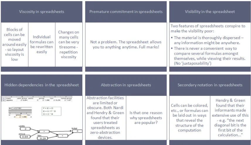
[image:27.612.91.519.408.656.2]As a point of comparison, at a conference in 2003, Green related more of an ‘armchair’ analysis of spreadsheet usability as an example application of the framework (Green, End-User Development: Current Experiences and Future Challenges, 2003). Figure 6 highlights several of the dimensional assessments. These assessments, by themselves, do not constitute an evaluation of usability, however. Ultimately, the evaluation must relate the suitability of the structural features of the spreadsheet, and the utilities provided by its environment for user interaction, to the way people use spreadsheets. In this analysis, Green, referring to the cognitive activities defined in section 2.2.2, looks at spreadsheets as devices for transcription and exploratory design. Figure 7 and Figure 8 provide his profiles for each type of user activity. Figure 9 presents his overall spreadsheet assessment.
Figure 7. CDs spreadsheet usability evaluation for transcription (Green, 2003)
Figure 9. Overall cognitive dimensions assessment of spreadsheet usability (Green, 2003)
2.3.4 Microsoft’s Visual Studio API usability evaluation
A more recent application of the cognitive dimensions framework was in the commercial realm, at Microsoft (Clarke, 2005). Visual Studio user experience group at Microsoft conducted usability study. The study involved determining if users would be able to use the .Net API to accomplish a set of tasks. Results indicated many users would face significant difficulties. The Microsoft user experience team observed study group participants struggling with documentation. Some participants would spend a lot of time looking for classes with which to accomplish the task. Other participants ‘stumbled upon’ documentation for classes they could use, but, even after stumbling upon these classes, they continued to search for something else
The implementation team's first reaction was to change the documentation to clarify connection with the task. The user experience team suspected deeper issues and used the CDs framework to describe each usability issue in terms of specific dimensions. The results of the CD’s assessment suggested the reason participants continued to search for documentation was because the abstraction level of the classes that they stumbled upon was too low. They were expecting classes that corresponded more closely to their internal representations of the task. The ones they found were at too low a level of abstraction. The user experience team presented the CDs analysis and convinced development team to create classes at a higher level of abstraction that represented tasks in the way participants thought of them. A subsequent user group study indicated significant usability
improvement.
more relevant to API usability. As an example, ‘Abstraction Gradient’ became the ‘Abstraction Level’ exposed by the API. The complete set of cognitive dimensions used by the WinFX team follows.
1. Abstraction Level 2. Learning Style 3. Working Framework 4. Work-Step Unit
5. Progressive Evaluation 6. Premature Commitment 7. Penetrability
8. API Elaboration 9. API Viscosity 10. Consistency
11. Role Expressiveness 12. Domain Correspondence
2.4 Limitations and pitfalls in using the cognitive dimensions framework
As is true with most tools, the cognitive dimensions framework is limited in application and subject to the potential for abuse and misuse. The cognitive dimensions framework is limited in several ways. For one thing, it is only applicable to the evaluation of the
structural characteristics of notational systems and information artifacts. For another, it is limited to evaluating use for cognitive activities, as opposed to physical, for example the ability to manipulate a keyboard. One should keep in mind that the cognitive dimensions framework is only one tool for evaluating usability; there are many other approaches although few, if any, provide such an encompassing perspective.
Jason Dagit, et al (Using cognitive dimensions: Advice from the trenches, 2006), point out that use of the cognitive dimensions is limited in the same way that testing is limited. That is, just as one is not likely to ‘prove’ a design correct by testing it, it is not possible to ‘prove’ a design suitable for use with the cognitive dimensions. Using these
mechanisms, one may discover evidence of problems, but, as they say, ‘absence of evidence is not evidence of absence.’ Dagit further cautions against using the cognitive dimensions to convince oneself of the usability of a favored design and the tendency to downplay tradeoffs.
2.5 Use of the cognitive dimensions framework in this study
The proposed evaluation of graphical and textual hardware description language
3 Hardware description languages and VHDL
The VHSIC Hardware Description Language, or VHDL, is a hardware description language used in the design of digital electronic systems. (VHSIC stands for Very-High-Speed Integrated Circuit.) Significant numbers of electrical engineers use both textual and graphical VHDLenvironments to describe, verify and synthesize devices such as field programable gate arrays (FPGAs) and application-specific integrated circuits (ASICs). Section 3 introduces hardware description languages. It discusses the similarities HDLs share with programming languages, and offers the rationale for using HDLs as surrogates for studying programming language usability. The section concludes with a brief
overview of VHDL. The structure of the section follows.
Section
3
content
3.1 Hardware description languages and programming languages ...33 3.1.1 Design languages ...34 3.1.2 Programming languages and HDLs are similar in function ...35 3.1.3 Programming languages and HDLs are similar in form ...36 3.1.4 Studying HDL use to further understanding of VPL usability ...37 3.2 VHDL Overview...37 3.2.1 History and aims ...37 3.2.2 Modeling digital systems ...38 3.2.3 Types of models and abstraction levels ...40 3.2.4 VHDL modeling ...41 3.2.4.1 Separate definition of external interface and internal implementation ...41 3.2.4.2 Entity declarations ...42 3.2.4.3 Port declarations...42 3.2.4.4 Modeling function...43 3.2.4.5 Modeling structure ...44 3.2.4.6 Language constructs...45
3.1 Hardware description languages and programming languages
specification languages, machine code, query languages, markup languages, configuration file formats, and more.
3.1.1 Design languages
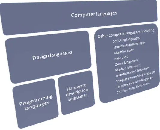
Programming languages and HDLs are design languages. Within the context of this study, the term design language denotes a subset of computer languages and includes programming languages and hardware description languages. Smedley and Cox (1997) use the term, design language, similarly, citing as examples: “languages often included in computer-aided design environments, and VHDL and other such languages used to describe electronic devices,” however, they exclude programming languages from the category. They do note that programming is a design activity, and the unsurprising fact that design languages are very similar to programming languages. Correctly, they observe that the use of these kinds of languages serves two purposes: 1. to describe designs for those who must create, understand and modify them, and, 2. to precisely encode such designs in a way that allows for the automatic synthesis of a finished product.
The categorization, depicted in Figure 10, that groups programming languages (one could refer to them as software description languages, as well) and hardware description
languages together, as design languages, emphasizes,
[image:35.612.170.437.465.682.2]1. the design-centric use of programming and hardware description languages, 2. the similarities between programming languages and HDLs, as well as, 3. their uniqueness amongst other categories of computer language.
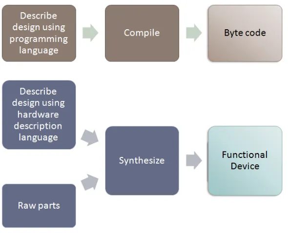
At present, design languages exist in two domains, software and electronics. In software, the finished product is an application in machine code where the process of constructing it is compilation. In electronics, the finished product is a functional device and the process for creating it from a design language specification and raw parts is synthesis. Figure 11 depicts the analogous processes for implementing logic in software and hardware. Another feature of design languages is the facility to verify all or part of the design before fabricating the finished product. This is truer, due the costs of realizing physical devices, for hardware description languages than for programming languages.
Figure 11. Analogous processes for implementing discrete logic in hardware and software.
3.1.2 Programming languages and HDLs are similar in function
The relationship between programming languages and hardware description languages goes beyond their use as design tools. Programming languages and HDLs are for designing functionally similar systems. Typically, electronic systems contain both hardware and software. Consider the system fragment depicted in Figure 12 with functional elements for command and control, and for data processing. The extent to which designers implement certain functionality as hardware, as opposed to software, is the result of architectural and performance trade-offs. Cost, speed, schedule, reliability and other factors drive the mix of functionality realized with devices that process signals through networks of logic gates, and programmable devices that process encoded
Figure 12. A typical electronic system fragment with hardware and software components.
3.1.3 Programming languages and HDLs are similar in form
Programming languages and HDLs provide similar mechanisms for describing behavior. As pointed out previously, hardware description languages commonly have facilities that allow for the verification of designs and parts of designs, before fabrication of the final product. Within the software domain, design verification occurs by various means depending on the complexity and type of design. For applications developed and run on the same computer architecture, pre-compilation verification may not be important if the developers are willing to incur the effort and time to compile elements of the design in order to test them. Another mechanism, sometimes the only one, provided by some programming environments for executing programs is interpretation. Interpreters allow for rapid execution of design fragments, however, frequently performance critical programs rely on compilation, and associated hardware-specific optimizations. A third verification scenario involves the use of processor emulators. Developers rely on
emulators, which may be software (virtual) or hardware (e.g. development kits), when the hardware system targeted by the software is also under development and not available. In the hardware domain, developers desire verification before committing what are typically significant resources to the fabrication of hardware. Simulation, analogous to interpretation, is the most common approach, although, sometimes developers will use hardware emulation if the software device models cannot execute at practical speeds. The motivation to support behavioral verification resulted in the evolution of HDLs with programming-language-like constructs from simpler notations such as netlist languages that specified only the connectivity of design components. Developers use today’s HDLs to model the behavior of designs at multiple levels of abstraction, and to design
3.1.4 Studying HDL use to further understanding of VPL usability
So, even though HDLs may be very similar in function and form to programming languages, why study them to understand programming language usability? Why, not study programming language usability by looking at programming languages
themselves? The answer to the last question is that one most certainly can. The problem is that sufficiently constrained cases in terms of complexity, user types, and designs are hard to come by.
The answer to the first question is that HDLs offer the unique characteristic of being programming-language-like systems borne from the discipline of computer science and software engineering for use by designers of complex systems, in other areas of expertise. One might argue that computer scientists develop programming languages for use by software engineers. In reality, however, most programming languages demand a deeper understanding of computer science for programmers to be proficient. In many cases, usability simply does not seem to have been a design consideration. This study considers that computer scientists and engineers, designing HDLs with programming-language-like facilities, for electrical engineers, at least thought about usability.
The hardware description language, VHDL, is very programming-language-like, tracing its lineage to the ADA programming language; this was by government edict (Ashenden, 1996). VHDL is a standard for digital design, with widespread use in industry.
Significant numbers of users work in both graphical and textual VHDL environments. Furthermore, there seems to be a tendency for users to prefer one environment to the other. This situation, in effect, represents a more highly constrained situation, with large numbers of users, than one might hope to find by looking at C++ and Visual C++, as an example. User types are similar (digital designers), designs are similar, designs are non-trivial. There is a chance of correlating usability differences with the availability of visual methods.
3.2 VHDL Overview
The VHSIC (very-high-speed integrated circuit) Hardware Description Language (VHDL) is a design language for modeling digital systems. In the commercial world, VHDL is one of the two predominant HDLs used in the area of digital design (Verilog is the other). Electrical engineers designing digital systems typically use one HDL, or the other, or both. Much of the discussion in the ensuing paragraphs regarding VHDL applies to Verilog also. The overview of the modeling of digital systems draws heavily from The Designer's Guide to VHDL (Ashenden, 1996); the summary of VHDL’s aims and history draws from instructional materials on the RASSP program’s web archive (Stinson, 2007).
3.2.1 History and aims
VHDL as part of their VHSIC program, launched in 1980. In 1983, the program awarded the contract to develop VHDL to a team from Intermetrics, IBM and Texas Instruments. In August 1985, that team released the last government-sponsored version of language. The Institute of Electrical and Electronic Engineers (IEEE) further developed the language and released the Standard VHDL Reference Manual (IEEE Standard 1076), in 1987, a major revision in 1993, and two minor revisions in 2000 and 2002.
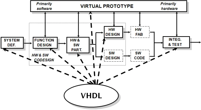
[image:39.612.92.517.307.541.2]While VHDL is in many ways like a general-purpose programming language, its principal use is for modeling digital systems, from the gate to the system level. Digital systems are, borrowing from Ashenden (1996), any digital circuits that process or store information. Designers realize such systems using assemblies of interconnected printed circuit boards, configurable devices such as field-programmable gate arrays (FPGAs), custom devices like application-specific integrated circuits (ASICs) and discrete logic devices. A digital system can be relatively complex or as simple as an individual logic gate. The need to model complex digital systems persists throughout the development cycle. Figure 13 indicates the design activities VHDL modeling supposes to support.
Figure 13. The role of VHDL in digital system design. From (Stinson, 2007).
3.2.2 Modeling digital systems
3.2.2.1 Requirements definition
One of the steps in the design cycle is requirements definition. Designers need
requirements that are complete, unambiguous and that do not constrain implementation options. Sometimes, well-written requirements documents meet these criteria, but when they do not, the consequences can be costly in terms of overall cycle time as design teams resolve ambiguities and discover and deal with omissions late in the game. System
architects can use formal models to specify requirements unambiguously. Models can define the external interface, as well as, the performance of the system at a ‘black-box’ level of abstraction that leaves the designer free to explore alternative implementation options.
3.2.2.2 Functional partitioning
Developers use models to partition designs into logical and manageable elements. Models of the partitions can define their external interfaces and their behaviors at various levels of abstraction. The structural partitioning of complex designs facilitates the allocation and management of design tasks to different engineers. The ability to model behavior at different levels of abstraction makes it possible to test elements at the system-level using simulation as the design progresses, while other elements are in different states of
completion.
3.2.2.3 Design documentation
Another advantage to using formal models is in the area of design documentation (recall, this was one of the government’s original motivations for the development of VHDL). Developers cannot always anticipate and document all the ways others may attempt to use their designs. If developers provide functional models with their system, users and integrators can determine for themselves how designs will function in specific
applications and as integral components of larger systems.
3.2.2.4 Design verification
Formal modeling lends itself to design verification by two means, formal verification and simulation. The former is the proof of the correctness of a design and requires
mathematical definitions of the required function and of the modeling language semantics. Formal verification is difficult to perform efficiently with designs of real-world complexity but remains an on-going area of research (Abraham, 2006). Simulation, on the other hand, is in widespread commercial use.
response, the simulation deems the implementation correct, otherwise not. Verification via simulation assumes the input covers all possible scenarios of use, and the problem of test coverage is itself an area of research (Ashenden, 1996).
3.2.2.5 Circuit synthesis
One of the handiest applications formal modeling makes possible, is the automated synthesis of physical circuits from abstract representations. This in effect relieves designers of implementation details and allows more attention to requirements
conformance. Automating the translation from requirements to implementation reduces opportunities for errors, as well, and increases the reliability of the design process.
3.2.2.6 Integration and test
As previously stated, integrators can use models to understand, in advance, how a system might operate within a larger context. Modeling and simulation is similarly useful during the integration and test phase. As integrators observe unexpected behaviors are discover unanticipated circumstances, they can simulate the input scenario and observe the response predicted by the model to aid in the process of isolating root cause.
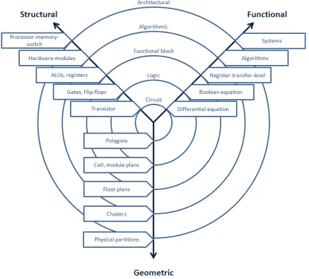
3.2.3 Types of models and abstraction levels
Figure 14. Gajski-Kuhn Y-chart axes represent different modeling dimensions and the concentric rings indicate abstraction levels, with the less abstract towards the center.
3.2.4 VHDL modeling
As noted, VHDL has features that allow for the modeling of structure and behavior, within a range of abstraction levels, in order to offer digital systems designers the advantages laid out in previous sections. This section describes the basic VHDL modeling constructs for describing the structure and behavior of digital systems.
3.2.4.1 Separate definition of external interface and internal implementation
One of the most fundamental aspects to VHDL is the separate definition of interface and internal implementation. In this respect, VHDL has a very object oriented feel. A
architecture bodies for any one entity. VHDL has facilities for describing the function of components structurally, i.e., as a network of simpler components. VHDL also provides programming-language-like constructs such as variable assignment, control flow, iteration and file I/O to model complex behaviors at higher levels of abstraction.
Figure 15. The basic elements of a VHDL model are the entity and architecture body. The entity defines the external interface; the architecture body describes the internal implementation. Architecture bodies
representing alternate implementations or different levels of abstraction can be associated with the same entity.
3.2.4.2 Entity declarations
The main job of the entity is to declare component interface signals. Figure 16 provides an example VHDL entity declaration and an analogous graphical representation. The ENTITY statement names the entity and the PORT statement implements its interface by specifying each signal, and each signal’s type and dataflow direction. The optional GENERIC clause allows for passing parameter values from an instantiation of the entity to underlying architectures. The END statement terminates the entity declaration.
Figure 16. An entity declaration and an analogous visual representation. (Stinson, 2007)
3.2.4.3 Port declarations
initial values. Simulators will assign the initial value by default if there is nothing driving it at the start of a simulation.
3.2.4.4 Modeling function
VHDL architecture bodies describe component function. Multiple architectures can exist for any entity, but entity instantiations must specify which one, of possible alternates, to use. Architecture bodies have two sections, a declarative section and a statement section. The declarative section is for type declarations, internal signal declarations, component declarations and subprogram declarations. The statement part defines the structure and function of the component using component (entity) instantiation statements, concurrent signal assignment statements and process statements. The keyword ARCHITECTURE marks the beginning of the architecture body, BEGIN marks the beginning of the statement section; END marks the end of the end of the architecture body.
There are two styles, behavioral and dataflow, for specifying component functionality with VHDL. Dataflow descriptions consist of concurrent signal assignment statements. Behavioral descriptions use programming-language-like sequential constructs (loops, variables, conditionals, etc.) within VHDL processes. Behavioral descriptions describe function more abstractly and may have little resemblance to the physical implementation.
3.2.4.4.1 Behavioral architectures
Typically, as designs progress, models become less and less abstract until they represent functions realizable from interconnections of physical components. Early on, however, a model might be specified using abstract constructs such as the sequentially evaluated IF-THEN-ELSE clause in Figure 17.
3.2.4.4.2 Dataflow architectures
Another way to express the functionality of the half adder is with concurrent signal assignment statements as shown in Figure 18. VHDL modelers refer to this type of architecture body as a dataflow architecture. Note that one cannot use sequentially evaluated statements like the IF-THEN-ELSE construct, in dataflow architecture bodies (i.e., outside a process).
Figure 18. Dataflow architecture body for half-adder entity (Stinson, 2007).
3.2.4.5 Modeling structure
Figure 19. Half-adder functional schematic (Stinson, 2007).
Another type of architecture body describes the internal implementation of the entity as a network of interconnected components. The functional schematic in Figure 19 represents one such implementation. Figure 20 provides a corresponding structural VHDL
description.
Figure 20. Structural architecture body for half-adder entity (Stinson, 2007).
3.2.4.6 Language constructs
VHDL has all the features to classify it as a general purpose, interpreted programming language. Instead of an interpreter, a simulator is required for program execution. Simulators have the additional facilities for evaluating the representation of concurrent execution necessary for the emulation of digital hardware. This section cursorily
3.2.4.6.1 Data types
All VHDL port, signal and variable declarations must include a type or subtype
specification. A set of predefined data types are available in the standard VHDL package, but user can define subtypes (range-constrained types) and their own types.
There are three classes of VHDL data types: scalar, composite and access. Scalar types are atomic units of information, composite types are arrays and records, and access types are similar to pointers in other languages. Scalar types include integer, real, enumerated, and physical. Integer and real types are straightforward; their ranges are simulator specific. Enumerated data types allow users to define lists of legal values. Figure 21 provides an example declaration and use of an enumerated data type, binary, with legal values ON and OFF. An example of where this is useful is in defining variables that store the state values of a finite state machine. Physical data types are for values that have associated units. In addition to name and range, users must also specify the units as shown in Figure 22. The only predefined physical type is time.
Figure 21. Example declaration and use of enumerated data type (Stinson, 2007).
Figure 22. Example physical data type definition (Stinson, 2007).
record). Figure 23 provides an example of array declaration and use, and Figure 24 provides an example of record declaration and use.
Figure 23. Example array declaration and use (Stinson, 2007).
Figure 24. Example record declaration and use (Stinson, 2007).
Access types are like pointers in other programming languages and are handy for creating data structures that require dynamic memory allocation.
3.2.4.6.2 Objects
3.2.4.6.3 Sequential and concurrent statements
VHDL is a concurrent language and all processes and concurrent signal assignments execute concurrently. (Concurrent signal assignment statements are essentially one-line processes.) Statements within VHDL processes execute sequentially. The sequential statements support iteration, control flow, variable assignment, etc. The dual nature, sequential and dataflow, of VHDL allows users to intuitively model hardware systems, which are essentially parallel networks of data processors, and, at the same time, use sequential statements to model functionality.
3.2.4.6.4 Packages and libraries
VHDL provides packages as a mechanism for storing reusable user-defined types,
subprograms, constants, and more. VHDL libraries are reuseable collections of packages, entities, and architectures.
3.2.4.6.5 Predefined operators
4 Analysis
method
Figure 25. Conceptual system under analysis
Figure 25 depicts the system under consideration. The user, the author, is an experienced digital designer, familiar with the hardware language, VHDL, and both graphical VHDL and textual VHDL environments. The notation is the hardware description language VHDL. The use of the notational systems, the graphical and visual VDHL environments, is exploratory design within the domain of digital system design.
This section describes the analysis method, and the representative design and other tools that support the analysis. The structure of the section follows.
Section
4
content
4.1 Method
To assess the usability afforded by the visual features of a graphical VHDL environment, the study applied the cognitive dimensions framework to both a textual VHDL
environment and a commercially available graphical VHDL environment. To re-familiarize himself with the two environments, the author implemented the same
benchmark design in both environments. The experience was the basis for the respective cognitive dimensions usability profiles. A comparative analysis of the graphical VHDL and textual VHDL profiles attempts to relate usability impacts to graphical methods.
4.2 The benchmark design
The benchmark design, a timer, selected from the graphical design environment’s tutorial (Mentor Graphics Corporation, 2005), is simple, yet non-trivial requiring elements of signal decoding and control. Figure 26 provides the specification.
Figure 26. Timer specification used in usability evaluation of textual and graphical design environments (Mentor Graphics Corporation, 2005)
4.3 Cognitive dimensions walkthrough assessments
by Green and Blackwell (Blackwell & Green, A Cognitive Dimensions Questionnaire, version 5.1.1, 2007).
4.4 Usability requirements
The study established usability requirements, in terms of the cognitive dimensions for a notational system for digital design engineers (novice and expert), performing the cognitive activity of exploratory design within the domain of digital system design. The study then evaluated performance margin for the two notational systems with respect to the established usability requirements.
4.5 Visualizing the results
[image:54.612.92.525.326.620.2]Steve Clarke at Microsoft developed an analysis tool for visualizing cognitive dimensions profiles. Using a similar visualization (Figure 27), the analysis presents comparisons of the visual and textual VHDL environment cognitive dimensions profiles.
4.6 Comparative analysis
5 Results
and
analysis
Each cognitive dimension represents a measure that influences the suitability of a
notational system for a given cognitive activity. Designers of notational systems, such as programming language environments and digital system design environments, can specify usability requirements as a set of value ranges along each cognitive dimension. The first part of this section presents such a set of usability requirements for a digital system design environment like the ones considered in this study. The ‘walk through’ section, offers the rationale for each requirement, and performance evaluations of both the textual and visual VHDL environments. The walkthrough develops the cognitive dimensions profile for each system and provides comparison in terms of performance margin. Lastly, a comparative analysis attempts to relate the results to the use of visual description methods. The structure of the section follows.
Section
5
content
5.1 Usability requirements for digital system design...57 5.2 Cognitive dimensions walk-through assessments...58 5.3 Comparison of visual and textual VHDL cognitive dimensions profiles ...74 5.4 What the usability evaluation says about visual methods...76 5.5 Use of the cognitive dimensions framework ...78 5.6 Recommendations for further study...79
5.1 Usability requirements for digital system design
As a first step, the analysis established usability requirements, in terms of each cognitive dimension, for a digital system design environment. This enabled the comparison of the evaluated visual and textual digital system design environments, not only to each other, but also to an ideal system (in this case, the author’s ideal). Table 7 presents the
Table 7. Usability requirements established for digital system exploratory design
Min Max
ABST Abstractions, abstraction hunger, and abstraction barrier Typical High
HIDD Hidden dependencies Typical
PREM Premature commitment and enforced lookahead Low