Environment Based on Lean Cuisine
A thesis presented in partial fulfilment of the requirements for the degree of Master of Science in Computer Science at Massey University
Jianpeng
Gu
1995
MASSEY UNIVERSITY
\\Ill 11111\1111 \\11\
\\I\\
\Ill
The integrated user interface development environment based on the Lean Cuisine graphical notation [Apperley & Spence, 89] is a combination of software tools used to support user interface development from initial design, rapid prototyping through to direct implementation. This thesis describes the development of three software tools used in the integrated user interface development environment.
The Lean Cuisine graphical editor (Elc) provides an interactive design environment for graphical specifications of menu-based interfaces and shows that the Lean Cuisine notation described in [Apperley & Spence, 89] has been implemented in a practical computer environment as an interactive interface design tool.
The user interface simulator (Sic) is a very effective and reliable interface simulating and testing tool which supports quick and convenient user interface simulation. Using Sic, a menu interface can be quickly simulated in its design environment, where a menu-based interface can be partially or wholly simulated and invalid menu structures can be dynamically modified, or in its application environment, where evaluators are given a real feel of how this menu-based user interface works.
The user interface generator (Glc) is used to generate basic interface source code files for a user interface from its Lean Cuisine graphical specification file, and a working model of a user interface can be easily and quickly implemented without programming.
The integrated user interface development environment based on the Lean Cuisine graphical notation [Apperley & Spence, 89] successfully integrates a graphical notation, the visual programming technique, with an existing programming toolkit and offers advantages over other User Interface Programming Toolkits, language-based UIM.Ss and current Visual Programming Tools. It supports three main phases ( design, prototyping and implementation) of the graphical user interface development lifecycle. This approach has not been found in previous user interface development tools and user interface
I would like to thank my supervisor Professor Mark Apperley for his guidance, encouragement and help during my study.
Thanks also extend to all staff and postgraduate students in the Department of Computer Science for their assistance and fiiendship.
Abstract
Acknowledgments
Table of
Contents
Chapter l. Introduction ...
l
1. 1. User lnterface Development ... 1
1 .2. The Limitation of Current Approaches... 1
1 .2. 1. User Jnterface Programming Toolkits ... 1
1 .2.2. UIMSs ... 2
1.2.3. Visual Programming Tools ... 2
1 .3. A New Menu Jnterface Development Environment... 3
1 .4. Overview of the Thesis ... ." ... 3
Chapter 2. Related Research
5
2. 1. Jntroduction ... .... . ... .. ... .. ... .... . .. .. .. . ... ... .. . . .. . ... ... .... .. ... ... . . .. ... .. ... 52.2. MIKE ... 6
2.3. Peridot ... 7
2.4. The UofA
*
UIMS ... 82.5. Mickey ... 10 2.6. Devguide .... .... .. .. .. .. .... .. .. .. .. .. .. .. . .... .. ... ... .. .... . .. .. .. .. ... .. . .. ... ... ... .. ... 1 1 2.7. SCENARJOO ... 13
2.8. GENIUS ... 14
2.9. UIDE ... 15
2.10. Summary ... 15
Chapter 3. J\,1 otivation ...
17
3. 1. Software Development Lifecycle ... 17 3.2. Graphical User Interface (GUJ) Development Lifecycle ... 22
3 .3. Current Graphical Environments ... 25
3 .4. Notations for Dialogue Specification... 27
3.4.1. Textual Notations ... 27
3.4.2. Graphical Notations ... 28
3.4.2.1. Transition Networks ... 28
3.4.2.2. Lean Cuisine Notation ... 31
3.5. Problems with Existing User Interface Developing Tools ... 33
Chapter 4. The Lean Cuisine Graphical Editor
•••.••••••...••...•35
4. 1 . Introduction ... 3 5 4.2. Menu Structures in the Lean Cuisine Visual Notation ... 35
4.3. Overview ofElc ... · ... 38
4 .4. The Basic Graphical Primitives ... 41
4.5. Creating Basic Lean Cuisine Trees ... 44
4.6. Basic Meneme Operations ... 45
4.7. Basic Tree Operations ... 48
4.8. Menu Interface Simulation at the Design Stage .. ... ... ... ... 53
4.9. Lean Cuisine Graphical Specification File ... 55
4.10. The Development Environment ofElc ... 55
Chapter 5. The User
Interface Simulator ...
...
57
5.1. Interface Simulation and Test ... 57
5.2. Some Existing Interface Testing Tools ... 57
5.3. Overview ofSlc ... 59
5.4. Interface Simulation in Its Design Environment ... 59
5.4.1. Change the Mode ofElc ... 59
5.4.2. Partial or Whole Simulation of a Menu System ... 61
5.4.3. Modifying Invalid Menu Structures During Simulation ... 63
5.4.4. Testing the Interface ... 65
5.5. Interface Simulation in Its Application Environment ... 67
5.6. Functions of the Le run time Kernel ... 68
5.7. Summary ... 69
Chapter 6. The User Interface Generator
···70
6.1. Overview of Glc ... 70
6.2. Using Glc to Generate Interface Source Code Files... 70
6.3. Files Generated by Gk ... 71
6.4. The Development of Real Application Procedures ... 72
6.5. Summary ... 72
Chapter 7. Detailed Examples of Application Development ... 74
7 .1. Development of TaP Interactive Application ... 74
7.1.1. About TaP ... 74
7 .1.2. Using Elc to Create the LC Graphical Specification of TaP ... 76
7 .1.3. The Direct Simulation Based on the LC Graphical Specification File . . . 91
7.1.4. Using Glc to Generate TaP User Interface Source Code Files ... 95
7.1.5. Link Application to TaP User Interface ... 96
7.1.6. TaPinUse ... 98
7. 2. Development of the ELC Lean Cuisine Graphical Editor... 102
7.2.1. About ELC ... 102
7.2.4. The Direct Simulation Based on the LC Graphical Specification File ... 114
7.2.5. Using Glc to Generate ELC User Interface Source Code Files ... 116
7.2.6. Link Application to ELC User Interface ... 117
7.2.7. ELC in Use ... 118
7.3. Summary ... · ... 120
Chapter 8. Conclusions
.•..••...•..••.••....•..••.122
8.1. Review of the Integrated Interface Development Environment ... 122
8.2. Conclusions ... 124
References
Appendix I.
Appendix II.
...
The Lean Cuisine Notation ...
.
..
.
...
.
... .
Program Listing
...
... .
126
132
Introduction
1.1.
User Interface Development
Creating a good user interface for a system is a difficult task, and the software to support user interfaces is often large, complex, and difficult to debug and modify [Myers, 88]. Current techniques for the specification and development of user interfaces can be divided into three basic groups: User Interface Programming Toolkits, User Interface Management Systems (UIMSs) or User Interface Development Systems (UIDSs), and Visual Programming Tools. Although many tools have been created to make user interfaces easier to design and implement, their development is stiJl a hard work. It is generally the case that as user interfaces become easier to use for the end user, they become more complex and harder to create for the user interface creator. Direct-manipulation user interfaces are particularly difficult to create because they often provide elaborate graphics, many ways to give the same command, a mode free interface, and rapid semantic feedback [Myers, 89].
1.2. The Limitation of Current Approaches
Many solutions for finding better methods of creating good user interface have been proposed in the areas of User Interface Programming Toolkits, User Interface Management Systems(UIMSs) and Visual Programming Tools. Many tools have been created to make user interfaces easier to design and implement but each method has its own attendant problems.
1.2.l. User Jn1erface Programming Toolk.i1s
of using toolkits are that they provide limited interaction styles, lack of support for easy
prototyping, difficulties in ease of use at least as great as the base language, no
abstraction mechanisms, no path of communication between the user interface designer
and the end user [England, 90], and they cannot be used by non-programmers.
1.2.2. UIMSs
The problems with User Interface Programming Toolkits have led to the creation of
UIMSs (User Interface Management Systems). UIMSs attempt to provide solutions to
some of the problems of conventional programming toolkits. In most UIMSs, the
designer specifies the user interface with a special purpose language and provides
abstract user-system dialogue specification mechanisms. Their descriptions are generally
interpreted, thus aiding prototyping to some degree. But they still require programming,
and with an ordinary text editor it is not easy to create, debug, and modify a textual
specification file for a complex user interface, and textual specifications of user interfaces
are too complicated to be understand and used. So language-based UIMSs are not
suitable for the non-programming interface designer.
1.2.3. Visual Programming Tools
Visual Programming Tools offer advantages over interface toolkits and language-based
UIMSs inherent in their direct manipulation approach. No programming language has to be learnt, and immediate feedback is provided to the designer. Visual user interface tools fall into two categories, those built on existing programming toolkits and those aimed at
more general user interface construction. An example of former category is
OpenWindows Developer's Guide (Devguide) [SUN, 90B], it is a graphical user
interface design tool built on XView user interface toolkits and that allows the user
interface designer to interactively construct the user interface by drawing the desired
interface primitives on the screen. The interface is automatically prototyped. But
Devguide cannot offer this drawing function to all interface primitives~ for example,
Devguide uses the menu editor window to construct menus. Also Devguide cannot
organize a complex user interface because it lacks specification of the user interface and
cannot support the dynamical creation of hierarchical menus from their specification at
run-time. An example of later category is Peridot [Myers, 88] which offers programming
by demonstration for component construction and component behaviour specification. The information used to construct an interface is implicit and therefore hidden in the system. Also the interventions of the inference mechanism can become tedious for an
1.3. A New Menu Interface Development Environment
In order to make user interface development much easier and quicker, a new menu user interface development environment based on the Lean Cuisine [Apperley & Spence, 89] diagrammatic design tool has been built. The main goals for developing this menu user interface development environment are :
• To provide an interactive menu interface design environment and allow user
interface designers who are not programmers to create menu interfaces by using Lean Cuisine graphical notation.
• To provide an automatic prototype environment and allow user interface designer to
simulate the design partially or wholly at any design stage.
• To provide a tool used to generate source code for a user interface from its Lean Cuisine specification file.
• To support user interface development from design, simulation to direct
implementation based on the Lean Cuisine graphical description.
• To ensure a true separation of concerns between the application and the user interface.
The new menu user interface development environment based on the Lean Cuisine graphical notation [ Apperley & Spence, 89] aims to fulfil some of the deficiencies
outlined in User Interface Programming Toolkits, UIMSs and Visual Programming Tools
above, and to support the graphical user interface development lifecycle. The details of how these goals were achieved will be discussed in later chapters.
1.4. Overview of the Thesis
Chapter 2 presents a review of several existing user interface development tools in
chronological order, and briefly discusses the limitation of these tools.
Chapter 3 discusses models of software development lifecycle and graphical user
development, notations for dialogue specification, and the integrated interface development environment based on the Lean Cuisine graphical notation.
Chapter 4 briefly reviews menu structures in the Lean Cuisine graphical notation, then
describes in detail the basic structure and functions of Elc, the Lean Cuisine graphical
editor, and discusses how a user interface designer interactively design the graphical
dialogue specification by using the Elc tool. The user interface simulation at the design
stage, and the implementation environment ofElc are also discussed.
Chapter 5 briefly reviews some existing interface testing tools and describes in detail
Sic, an interface simulating tool used in the Lean Cuisine menu interface development environment to support quick and convenient user interface simulation based on the Lean
Cuisine graphical notation.
Chapter 6 describes in detail Glc, a software tool used to generate basic user interface source files for a user interface from its Lean Cuisine graphical specification file.
Chapter 7 gives two detailed examples of software development in the menu interface
development environment based on the Lean Cuisine graphical notation, and shows that a menu-based user interface can be rapidly simulated, modified and implemented based on its Lean Cuisine graphical specification.
Chapter 8 reviews the integrated user interface development environment based on the
Related Research
2.1. Introduction
In recent years, significant advances have been made in the area of user interface development. A number of user interface development tools like user interface builders,
user interface management systems (UIMSs) or user interface development systems (UIDSs), and user interface development environments (UIDEs) have been developed and provided solutions to some of the problems of conventional programming user interface toollcits.
Some of these tools are designed to allow an interface designer to easily create, modify and generate an interface to an application through high level specifications [Apollo, 88;
Olsen, 86; Olsen, 89; Schmucker, 86; Singh & Green, 89a]. Each of these tools introduces its own notation (a special purpose language) for the higher level user interface specification. The language based notation can be used by the user interface designer to specify the interface's syntax [Apollo, 88; Olsen, 89; Schmucker, 86] or the application's semantics [Olsen, 86; Singh & Green, 89a]. The special purpose language used by these tools may take several different forms: menu networks, state-transition diagram languages, context-free grammars, event languages, decJarative languages and object-oriented languages [Myers, 89]. Obviously, these languages and tools can only be used by programmers.
Some of these tools are designed to let an interface designer define the user interface by placing objects on the screen with a mouse [Buxton et al., 83; Henderson, 86; Myers, 88;
Myers et al., 93; Sun, 90b]. These tools can be used by nonprogrammers or programmers and user interface can be created without conventional programming. But these systems are more difficult to build and only support the creation of a limited range of interface [Myers, 89].
2.2. MIKE
Olsen (1986) developed MIKE (the Menu Interaction Kontrol Environment) [Olsen, 86] in Pascal for Pascal programmers. The goals for MIKE's development [Olsen, 92] are:
• Provide a high level UIMS model that would allow many new user interface
capabilities to be automatically supported by the UIMS.
• Provide a dialogue specification model that would readily explained to nonprogrammers.
• Automatically generate a working interface from a minimal specification and then provide refinement tools for improving the generated interface.
• Integrate the visual layout specification with the dialogue and semantic specification.
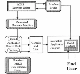
Figure 2. 1 shows the system architecture of MIKE. The four major components of MIKE system are the interface editor, the interface profile, the generated interface and the standard run-time code.
i, ... , .. •.·,···-···-·-·-····
Generated Semantic Interface
Compile
---Standard
MIKE
User Interface Code
and Link
Interface
!I
i---~
Profile
I!
Interactive Application Program
End
User
Figure 2.1. The system architecture of:MIKE [Olsen, 86].
In this Menu Interface Kontrol Environment, the interface designer works through the
graphical interface editor that provides access to the interface profile, which contains the
[image:13.572.111.441.356.658.2]MIKE does not have a separate dialogue specification; the dialogue is controlled by semantics and the presentation. :MIKE supports the user to extend the user interface by creating new macro commands by example. A major drawback of l\1IKE was its command line orientation and its limited range of interface techniques. In particular, it could not be used to provide the kinds of user interfaces that one finds on the Apple Macintosh and similar systems. In response to these difficulties, Olsen developed the Mickey system which will be discussed in section 2.5.
2.3.
Peridot
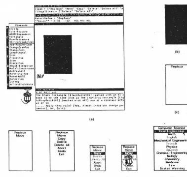
Peridot [Myers, 88) stands for frogramming by _Example for Real-time Interface Design Obviating Iyping and is a working prototype that is able to create many types of interaction techniques. Figure 2.2 shows a sequence of snapshots during the creation of a pop-up menu with Peridot .
co •• , .. 01
('U ' t h
(Jtt•P,,;t""' »0US(0critndtnt
t u·t,,.ial, Rwn•Pro>..:: edvr •
Ctr ,n froa$e hct •o•· uwrn-.. tat
,,.,nQ,Or,-.fnc Ctun4tf ont
Co,i,cn,ontl •[,u
,,.,u, ... ,
l.:on •ltu·uic,n
• 110ust-hcept h>n
it.cc~ lci:onnr• '"' lllctrcu,A l1 le 1nu,e1u, 1
JltUUl)USf.
:,1ut1on ~tr 1n9
••· Hc•?ro>ctoure
(d)
luu • (·ispl~•· ·•o••'" ·co,,y· ·o,hu· ·o,1cu ,.11-.,.
111c,a•llH•s • ('"Otletc• '"Och,c: •1l·
ID ii MI ZIWWPWR,.,,,,,,MHMMKMIMltnMIMR¥
a,,u, r,'4• lu• - •1epl.ac:c·
•••,>•,st•• - f.,9 -J~ Nil Nil Nil
19\c llac, rut,n9le lhO.ac..::tll1•j (e.N•co wuh tl'I II s ,,.., to tc the st•• .1111 . , the t1~nt,r.1y r,..:um:ilir Ill·) htCr.1ylte.:ttl47) l••r\•J wltn wkl) •i.o it ,1 con,u,,t orts
u of tl
... . . ,l.p1J1y thU ,.,1., ('ru. Alaost (•l o ~wt cunQ• "'•' •••tcr), -.c, Oull):
ce
Mo"" Copy
Delete
Delete IJ
Abort
Undo E•il
(e)
(a)
l•:C.-1•• U,~~1::-:-U
Abolt
Undo
E,.it
(f) (t)
(b)
(c)
th
I i1itJll~l1
_:NS_. ~
t"rt!'I..-Jl
Pllya.ic•
~11,11,i~I, a,....;c..1Engine,,r'rlQ
IIUogy 0-.;.1ry
l,Aedci-,8
low 8..aW.•t Wea ·
(h)
[image:14.580.76.456.353.713.2]In particular, Peridot uses an inferencing mechanism for placing the constraints based on
what the designer has drawn on the screen. This inferencing works not only for
placement of single items but also for conditional and interactive placements. Peridot also allows the interactive mouse behaviours of visual objects to be defined by example.
Peridot is very different from other graphical user interface development systems because
it lets the designer create the interaction themselves. It can create most of the interaction in the Macintosh Toolbox and its own interface [Myers, 89]. Peridot chiefly performs the
interaction-technique builder function, and does not provide the support for sequencing,
also called syntax or dialogue control of the user interface.
2.4. The UofA"' UIMS
Singh & Green ( 1989) developed a high-level UIMS called the UofA * UIMS [Singh & Green, 89a] which uses a high-level descriptions of the semantic commands supported by
the application to automatically generate the lexical and syntactic design of graphical
user interfaces. Figure 2.3. shows the structure of the UofA* UIMS.
Device Description (from library)
User 4----11~ Presentation
End User's Preferences (optional)
Command Description
Application
Figure 2.3. The structure of the UofA * UIMS [Singh & Green, 89a].
[image:15.572.58.517.397.638.2]component of the interface. Vu is an interface graphical tool that can be used by the designer to refine the presentation component produced by Chisel. Figure 2.4 shows an example of command description used by the UofA * UIMS.
;"Declare global arguments. Center of Mass (COFM), length of the limb (LENGTH) and mass of the limb (MASS) are subranges of real numbers, whereas bend (BEND) and rotation (ROTATE) angles are subranges of integers.
TORQUE represents a list of torque functions that the user can assign to limbs. LIMB is an interaction technique which implements 3-dimensional pick. The INFO window is used to display limb attributes.*/
COFM = [0.0 : 1.0) LENGTH= [1.0: 5.0) MASS = [1.0 : 20.0) BEND = [O : 360) ROTATE= [O: 360)
TORQUE = (TorqueFuncl TorqueFunc2 TorqueFunc3 TorqueFunc4
TorqueFunc5 TorqueFunc6) LIMB = pick3d
INFO = window
/* The commands are declared as follows. Command name is optionally followed by the syntax type and the selection type of the command. After this come the argument declarations. For each argument its type, range or enumerations, if any, and default value, if any, are specified. In the following declarations none of the commands specifies syntax or selection type.
The Add_Limb, Remove_Limb, Move_Limb, Show_Attributes, Change_Orientation Change_Length, Change_Mass, Change_Cofm, and Change_ Torque commands are declared as OPEN_ ENDED. The rest of the commands follow the default·
selection type which is CLOSE_ ENDED. The mass, length, cofm, bend, rotate, and torque arguments of the Add_Limb command assume the
Currently Selected Values (CSVs) of their respective interaction techniques•/
Change_Root (position : LIMB)
ADD_Limb { OPEN_ ENDED} (parenUimb: LIJ\1B, mass: MASS {CSV}.
length: LENGTH {CSV}. cofm: COFM {CSV),
bend: BEND {CSV}, rotate : ROTATE {CSV}. torque : TORQUE { CS V} ), .
Remove_Limb { OPEN_ ENDED).(limb: LIMI3)
Move_Limb { OPEN_ ENDED} (limb : LIMB, new_pnrent : LIMI3) Show_Attributes { OPEN_ ENDED} (limb: LIMB)
Change_Orientation { OPEN_ ENDED} (limb : LIMB, new_rotation : ROTATE, new_bend: BEND)
Change_Length { OPEN_ ENDED} (limb : LIMB, new_length : LENGTH)
Change_Mass { OPEN_ ENDED} (limb : LIMB, new_mass : !vlASS) Change_Cofm { OPEN_ ENDED} (limb: LUvlB, new_cofm : COFJ'.,.I)
Change_Torque { OPEN_ ENDED} (limb : LIMB, new_torque : TORQUE)
/* The Save, Load, and Exit commands do not have any arguments*/ Save( )
[image:16.577.64.506.124.698.2]Load( ) Exit( )
Figure 2.4. Command Description for the Skeleton Editor [Singh & Green, 91].
:.~-
----..
~.-.. :-·.:_
·
_...
_ .. ··:_-_.
...
··:
:
·
.
·.··:
._·_. . ._:.:-._, _::: . . , .· '.··.• • • ' •• ', • • ._ ' • • • • • • I . ' • • • • • ' • ~ •
Figure 2.5. The interface generated from the command description (shown in Figure 2.4)
can be refined in the vu environment [Singh & Green, 91].
2.5. Mickey
The Mickey [Olsen, 89] system was developed by Olsen (1989) to explore the language
UIMS paradigm in the context of direct manipulation interfaces. It was designed both as
an attempt to simplify the user interface specification process and to broaden the scope
of interfaces that could be modelled in a language-based UIMS [Olsen, 89].
Mickey extracts its user interface specificatio_n directly from the Pascal code. The
presentation issues are handled by the Macintosh resource editor. Figure 2.6a shows the
Pascal declarations of Mickey for a sample Macintosh menu styles and the corresponding
LlneWidth = 0-hinLine (•Name=Thin •). MedLlne ("Name=Medium•). Thick.Line ("Name =_Thick•)); fillColor = (BlackFill (•Name=Black•],
GrayFill('Name=Gray•),
WhiteFill (•Name=White") ); VAR
LlneSize (• Menu=Styles •): LtneWidth; ColorSetting (" Menu=Styles •): FillColor;
VAR
BoldText (' Menu=Styles Name=Bold Key=B') : Boolean; ltalJcText (• Menu=Styles Name=ltalic Key=I·) : Boolean;
UnderLineText (• Menu=Styles Name=Underline Key=U•) : Boolean; OutlineText (• Menu=Styles Name=Ouiline •) : Boolean;
ShadowText (' Menu=Styles Name=Shadow •J : Boolean;
(a)
(b)
Figure 2.6. (a).The Pascal declarations of Mickey for a sample Macintosh menu styles and (b ). the corresponding styles menu generated by Mickey from its Pascal declarations [Olsen, 89].
Obviously, Mickey 1s suitable for programmers to learn to use because of its programming language orientation. It is targeted specifically for application analysts
because it is driven by the semantic definition of the interface. The form of specification of Mickey leads to a very tight binding between a particular user interface style and a particular programming language[Olsen, 89].
2.6. Devguide
base window onto the workspace where each glyph turns into an interface element. Once
the elements of a user interface are in place, the designer can edit each individual
interface element by changing settings and values in a property window listing the
properties of that element. After creating an interface, the designer can see how its
elements look and feel when users use them. In Devguide's test mode, the interface is
automatically prototyped. What the designer sees is the interface the application will
have. When the interface has been specified the programmer has only to implement the
functionality of the application.
Devguide implements the OPEN LOOK look and feel for the application by generating
program ca11s to the XView user interface toolkit. The generated code is well formatted
and easily readable and can be edited or directly compiled. Figure 2.7 shows the
development procedure of a user interface by using Devguide.
guide
Save the interface as a GIL file
Interface source code
Running the result
Testing the interface
Linking interface code
with a lication code
Although Devguide is a commercial user intenace designing tool, it lacks a complete specification of the user interface. It does well in creation and layout of simple intenace elements, but when used to create or modify complex intenace elements, for example,
hierarchical menus, it causes confusion because it cannot give a clear and complete specification of menus and sub-menus. Although the hierarchical menus can be created
statically by using Devguide, Devguide cannot support the dynamic creation of hierarchical menus from their specification at run-time.
2.7. SCENARIOO
SCENARJOO [Roudaud et al., 90] is a UIMS which allows intenace designers to
prototype, develop, test and debug user interfaces either in a simulated or true application environment. The process used to build a user interface consists of creating
and modifying three internal database; the Widget database, the Dialogue database, and the Simulation database. Each database has its own interactive editor. The global
functional architecture for SCENARJOO is shown in Figure 2.8.
~
~
applieati . . ce--.-ieatien
strea:a
t
LJ
j
applinnen
eM-11Ser
In Figure 2.8, the Widget Editor is used to create and modify widgets; the Dialogue
Editor is used to construct event graphs which are used to decompose a complex
dialogue into simpler ones and contribute the visual aspects of the dialogue; the
Simulation Editor is used to create sets of application simulation data. The run-time
kernel is connected either to the simulation database or to the actual application, the
simulation database is used during prototyping and early debugging, and the connection
to the actual application is made for final debugging and tests. At run time, either the real
application or the simulation can be run, but not both together.
2.8. GENIUS
In the GENJUS [Janssen et al., 93) environment (GENerator for user Interfaces Using
Software ergonomic rules), user interfaces for database-oriented applications can be
automaticaJly generated from extended data models and petri net-based dialogue
descriptions. The GENJUS environment is shown in Figure 2.9.
Views
~---~ Dialogue Nets
.__
_____
__,Knowledge-based Generation
UIM:S Language
Figure 2.9. The GENJUS environment [Janssen et al., 93].
In the GENIUS approach shown in above, views are defined in the Entity Relationship
Diagram Editor (ERDE) based on the Entity Relationship (ER) data model, transitions
between views are specified in dialogue nets, a knowledge-based component generates
the static user interfaces from the view definitions. As a target system, an existing UIMS
is used. The dialogue nets as will are transformed into code for the UIMS. The GENIUS
software engineering methods. The specification of the dynamics is much easier with the
graphical dialogue net representation than with a textual language. In the current system,
refinements of the generated dialogue are done by means of the underlying user interface
management system, the support for maintaining consistency between view and dialogue
definition will be enhanced in the future work.
2.9.
UIDE
UIDE [Foley et al., 91; Sukaviriya et al., 93], the User Interface Design Environment
which utilizes a model of an application to automatically create an interface, is designed
to allow interface designers to easily create, modify, and generate an interface to an
application through high-level specification. Through UIDE, a designer creates an
interface for an application by first describing objects and operations in the application,
and then chooses various interface functional components by linking them to application
operations. Once the application model is mapped to interface functional components,
the UIDE run-time environment uses the specifications in the model to generate a desired
interface. Figure 2. 10 shows the run-time architecture of UIDE.
Application
Routines Application
Model
UIDE
Dialogue Manager
Help
User Interface
Figure 2.10. The run-time architecture ofUIDE [Sukaviriya et al., 93].
Currently, defining the model in the C++ version of UIDE is still done through the
standard C++ declaration and instantiation syntax. A visual tool to create an application
model has been planned.
2.10. Summary
Many current user interface management systems (UIMSs) are language-based UIMSs.
specification file for a complex user interface. Textual specifications are too complicated
to be understand and used by non-programmers, so these language-based UIMSs are
very hard to use [Myers, 88]. Existing user intetface development tools are not suitable
for both interface designers and application developers. Graphical layout tools lack
specification of the user interface. Very few UTh1Ss can provide software tools to
support user interface development from user interface design, user intetface simulation
Motivation
3.1. Software Development Lif ecycle
Software development lifecycles have their roots m engineering methods and more specifically in the procedures of system engineering [Sage & Palmer, 90], the use of the tools of system engineering to develop, analyze, and implement large-scale system is embedded in the several software development lifecycles in use today. The models of software development lifecycle are still the subject of current research, but a number of different general models of software development lifecycle have been applied to practical software development projects [Boehm, 88; Cattell, 91; Fairley, 85; Hix & Hartson, 93; Laplante, 93; Lee, 93; Martin, 88; Sommervi11e, 92]. Some of these models are: the waterfall model, the structured approach, the structured evolutionary rapid prototyping approach, the spiral model, and the object-oriented software development lifecycle.
The waterfall model of the lif ecycle
The initial waterfall lifecycle model has undergone numerous refinements, so there are many versions of this appearing in the literature [Boehm, 88; Bischotberger & Pomberger, 92; Laplante, 93; Sage & Palmer, 90; Sommervi11e, 92], and one of these is shown in Figure 3. 1 .
Re411Dft-n1s afinitien
I"
Sysiemandsoftware usign
'"
Inq,lementation and unit iesfuagi
'"
lniegratioa ani sysiem iesmtgl
t
Operation andJft2lllRnaJI.Ce
In Figure 3 .1, the software process is made up of five stages; they are requirements analysis and definition, system and software design, implementation and unit testing, integration and system testing, and operation and maintenance. In an ideal situation, each of the above stages could be carried out in sequence. Actually, the software process i~ not a simple linear model, the development stages overlap and feed information to ead: other; one more stages are often repeated.
The structured approach
The concept of the structured software development lifecycle was introduced b) Y ourdon [Y ourdon, 82]. The structured software development lifecycle model is showr in Figure 3 .2.
Activity Flow
Information
- - - Flow
~ \
~nversio~
Figure 3.2. The structured software development lifecycle model [Yourdon, 82].
The rune separate phases are shown in Figure 3.2; they are survey, analysis, desig1 implementation, acceptance test generation, quality assurance, procedure descriptio1
database preparation, and installation. Contrasting the Y ourdan structured softwa1 development lifecycle model with the waterfall software development lifecycle mode there is no difference in the stages specified, other than minor semantic ones [Sage ,
[Connell & Shafer, 89] are derived from a st,ructured development lifecycle v.,itl
number of necessary changes and consists of rapid analysis, prototyping, design, tuni
and testing. As opposed to the structured software development lifecycle discus!
above, the structured evolutionary rapid prototyping approach does not reqt.:
exhaustive analysis and design activities before implementation activity takes place c
also differs from traditional throwaway prototyping [Lee, 93]. The evolutionary ra1
prototyping process is shown Figure 3.3.
----Design Derivation
Operation & Maintenance
Figure 3.3. The evolutionary rapid prototyping process [Connell & Shafer, 89].
Jn the structured evolutionary rapid prototyping approach, the requirements document
produced to specify user profile and the initial user task model to be realized in the initi
prototype. The initial prototype is constructed. right after rapid analysis activity withot
going through any formal design activity and detailed design will be derived from a use:
approved prototype. The testing activity is not clearly defined in the structure
e\'olutionary rapid prototyping approach because a prototype has effectively undergor:
system testing throughout the lifecycle. The key to a successful structured evolutionar
rapid prototyping development is access to good software tools that allow rapi
construction and iterative evolution of prototypes. With its early prototyping activity an
prototyping approach shortens the development lifecycle span, increases user
satisfaction, and lowers development and maintenance costs. Fourth-generation
languages ( 4GL) provide high-level interpretive description of program functionality and
are widely adopted for prototyping database applications [Lee, 93].
The spiral model
The spiral model [Boehm, 88] of the software development lifecycle differs from the
waterfall model in that the waterfall model is a specifications-driven model but the spiral
model is a risk-oriented or risk-based model. An outline of the spiral model is shown in
Figure 3.4.
Determine
objectives,
alternatives,
Commitment
partition Requirements plan
life-cycle plan
Integration
anc test
plan
Plan next phases
Cumulative cost
Progress through steps
Evaluate alternatives, icentify, rescive risks
I
UnitI
'e<' Lt.; - L lnt~;rationlI
ano testI
Implementation! Acceptance
I
I test
I
I
Develop, verify
next-level prcct.:ct
The key characteristic of the spiral model is an assessment of management risk items at regular stages in the project and the initiation of actions to counteract these risks. Before each cycle, a risk analysis is initiated and at the end of each cycle, a review procedure assesses whether to move on to the next cycle of the spiral. In Figure 3.4 the radial dimension reflects the cost parameter as these costs accumulate over the several phases
completed at the time of use of the model; the angular dimension represents the progress made in the development at a particular cycle. The spiral model has been designed to accommodate all other models of development and a risk-oriented spiral model of process management forces the consideration of a11 alternatives and risks [Sommerville, 92]. The advantages of the spiral model are the introduction of the notion of risk assessment and risk management into the software development process. 1t is able to incorporate the best attributes of other software development lifecycle models and is well suited for iterative process[Sage & Palmer, 90].
The object-oriented software development lif ecycle
The object-oriented software development lifecycle [Lee, 93] shares some characteristics
with the rapid prototyping approach. Since object classes are abstract data types with
encapsulated data and methods, individual classes can be regularly refined while creating
new classes through inheritance mechanisms. The object-oriented software development lifecycle is iterative and evolutionary. Figure 3. 5 shows a object-oriented software
development lifecycle proposed by The Object Management Group (OMG).
Object
modelling
Lifecycle
Strategic modelling
Analysis modelling
Design modelling
Implementation modelling
Construction
Delivery
Coordination and reuse
Full definition
of the system
The object-oriented approach encapsulates data with corresponding operations, and employs polymorphic mechanisms such as cJass inheritance to allow incremental software development. With data encapsulation, object classes can be conveniently reused, modified, tested, and extended. As a software development approach, more recent developments have focused on object-oriented analysis and object-oriented design activities [Booch, 94; Yourdon, 94].
3.2. Graphical User Interface (GUI) Development Lifecycle
Graphical user interface development consists of several phases: the analysis of graphical user interface requirements, graphical user interface design, graphical user interface prototyping, graphical user interface evaluation, and graphical user interface implementation. The graphical user interface development lifecycle generally fo11ows that of software development, so some models of software development lifecycle discussed in
section 3 .1 can be adopted for graphical user interface development. But designing and
developing the graphical user interface is an iterative process of refinement that persists as long as there is sufficient motivation to modify an interactive system. Thus, any implementation should be based on a software architecture that supports modification of
the user interface [Bass & Coutaz, 91]. The key to the success of graphical user interfaces is user-centred design [Lee, 93]; it is not acceptable for designers simply to impose their view of an acceptable user interface on users, and the user must take part in the interface design process [Sommerville, 92] and give timely user evaluation and
feedback.
When a waterfall lif ecycle model or a structured software development lifecycle model is used for graphical user interface development, testing is the only stage to allow meaningful user feedback, any errors and problems introduced during the analysis or design stage will have to be found and corrected only at a very late stage, it can be costly if extensive design modifications are required. Although iterations are always incJuded in
various descriptions of the waterfall lifecycle model, it remains unclear when and
according to what criteria such iterations are to be carried out [Bischofberger &
Pomberger, 92]. These make the waterfall lifecycle model and the structured software
development lifecycJe model less appealing for graphical user interface development,
where timely user evaluation and feedback are critical to success.
The prototyping-oriented software development lifecycle model [Bischofberger &
has its strengths where the waterfall lifecycle model and the structured software
development lifecycle model display serious weaknesses. lt can be used for graphical user interface development because it supports the requirements definition. The user
interface specification is the most important part of the requirement definition and its
quality is decisive. The user interface specification and its underlying functional
behaviour can be represented much better and tested more effectively with an executable
prototype than in the case with other means of represents. A user interface prototype can
provide an ideal basis for communication between the user interface developers and the
users.
The "star" user interface development lifecycle (Figure 3.6) [Hix & Hartson, 93] shows that evaluation is to be applied to every user interface development activity, not just to
design.
DEPLOYMENT
SOFTWARE PRODUCTION
TASK/
FUNCTIONAU USER ANALYSES
EVALUATION
RAPID
PROTOTYPING
REQUIREMENTS/
SPECIFICATIONS
CONCEPTUAIJ FORMAL/DETAlLED DESIGN &
REPRESENTATION
Figure 3.6. The "star" lifecycle of user interface development [Hix & Hartson, 93].
[image:30.568.56.490.296.637.2]The object-oriented software development lifecycle model [Lee, 93] treats the graphical user interface development as an integrated object-oriented software development process. A task model based on the GOMS (Goals, Operators, Methods and Selection) model will guide the object-model construction. The task model and the object model are the high-level abstraction of a graphical user interface application. Developing a graphical user interface for a specific style guide becomes a straightforward mapping process.
The user interface development lifecycle proposed by Perlman [Perlman, 88] includes three main stages: design, evaluation, and implementation (Figure 3. 7) . The sources of design and redesign are personal experiences with previous development and popular
system, guidelines and standards provided by basic and applied research and experts, and
feedback based on evaluation of similar existing system and of prototype system. Formal models make predictions of the goodness of a user interface based on a formal specification of the design, without requiring implementation. Usage data contribute to an empirical evaluation after implementation of a preliminary version or a prototype. The user interface development lifecycle shown in Figure 3. 7 is often iterative, with many small changes in design being implemented and evaluated over its brief period [Perlman,
88].
Standards
Evaluation
Formal
Models
Guidelines
3.3. Current Graphical Environments
There are many graphical environments which provide hardware and software support
for graphical user interface development and application. Generally speaking, the
hardware support of a graphical environment includes user input devices (e.g., mouse,
keyboard) and graphics-display output devices (high-resolution graphical monitors). The
software support of a graphical environment includes graphical operating system ( e.g.,
OpenWindowsTM, Microsoft Windows™) and layered abstraction of software libraries
(e.g., Xlib, Xt Intrinsics, Motif, OPEN LOOK, XView, Macintosh Toolbox, Microsoft
Windows Libraries) which are used to assist the development of application software. In
different graphical environments, different layers based on different abstractions allow graphical application software to access various services provided by that graphical
environment.
In the X Window System, there are a number of primitive layers. The Xlib contains all the necessary low level primitives to construct X Window applications. This would be the lowest level that an application developer would work at. The Xt lntrinstics collects
together the Xlib primitives and provides a basic framework to construct and use
widgets. A number of style-specific toolkits are available with different layering
architecture. The Athena widget set (Xaw), the Motif widget set, and the OPEN LOOK
Intrinsics Toolkit (OLIT) are Xt-based widget sets, each of which is implemented as a software layer above the Xt Intrinsics. The XView toolkit is a Xlib-based toolkit and it
implements the OPEN LOOK graphical user interface. In the X Window System, the
typical software development environments are shown in Figure 3.8, and Figure 3.9.
Applications
Athena Widgets~
Motifl}Jidgets;
OLIT Widgets
Xt Intrinsics
I
Xlib Operating System
Application
XView Toolkit
I
Xlib
Operating System
Figure 3.9. The software development environment using XView.
In the Apple Macintosh graphical environment, graphical user interfaces are developed
by using Macintosh User Interface Toolbox which provides various resource services to
support a Macintosh-style graphical user interface implementation. The Macintosh
software development environment is shown Figure 3 .10.
Application
Macintosh Toolbox
Operating System
Figure 3.10. The Macintosh software development environment.
In the Microsoft Windows 3.x software development environment, there are a number of developing tools that support the development of graphical user interfaces. The most
common tools for Windows programming are the Microsoft C compiler and the
Microsoft Windows Software Development Kit (SDK), Borland C++ and Resource
Workshop, and Microsoft Visual Basic. The application program interface (API) of Microsoft Windows consists of al1 functions that Windows programs may cal1. A11 the
included in the Windows Software Deveiopment Kit (SDK). An import library inciuded in the SDK is used by dynamic linking to create an executable Windows program. The
three major dynamic link libraries included in Windows are a kernel library, a user library,
and a graphics device interface (GDI) library. The kernel library contains the tasking and memory management functions, the user library contains the windowing and user interface functions, and GDI library contains the Windows Graphics Device Interface
functions. The Microsoft Windows software development environment is shown in Figure 3.11.
"'Windows Application
Windows Software Development Tools
Vlindows Libraries
lv.ricrosoft Windows operating system
Figure 3.ll. The Microsoft Windows software development environment.
3.4. Notations for Dialogue Specification
There are many notations for dialogue specification. Existing techniques can be grouped into two classes; textual notations and graphical notations.
3.4.1. Textual Notations
The textual notations are special-purpose languages used by the interface designer to
describe dialogue specification and control. These special-purpose languages are
modify and understand. The languages used by many UIMSs to specify the interface are
poorly structured in software-engineering sense. Most lJIMSs require that the designer
learn a new special-purpose language and some of them are real programming
environments (e.g., MacApp, Mickey), so they are inaccessible to nonprogrammers [Myers, 89].
3.4.2. Graphical Notations
The graphical notations incorporate special-purpose symbols used by the interface
designer to describe dialogue specification and control in a graphical manner. For
example, the Lean Cuisine graphical notation [Apperley & Spence, 89] is based on tree diagrams used to describe the structure and the behaviour of menu systems. Transition
networks based on a set of nodes (states) and the links between them (state transitions)
have been eX1ensively used as a dialogue description technique, by both designers and
implementors, and are probably the most popular form of dialogue description currently in use [Apperley & Spence, 89]. There are other graphical notations used in the conteX1
of dialogue specification and user interface management systems, these graphical
notations are Petri nets [Bastide & Palanque, 90], event graphs [Roudaud et al., 90], and dialogue nets [Janssen et al., 93]. Event graphs can be used to describe the dynamic
visibility of objects within a graphical-interactive application. Dialogue nets are similar to
event graphs in modeJJing the dynamic visibility of objects needed for the coarse-grain
dialogue specification. Petri net objects are more powerful since general object flow and object manipulation can be described. However, they are more complex than event graphs and less suited for the earlier design phases [Janssen et al., 93). The following discussion focus attention on Transition networks and Lean Cuisine graphical notations.
3.4.2.1. Transition Networks
Transition networks, also known as finite state machine diagrams or state transition diagrams, consist of nodes that correspond to a state and directed arcs that connect
nodes. ln a transition network, the dialogue is shown as being in a particular state
awaiting the neX1 interaction with the user [Jones, 91b]. Arcs out of each state are
labelled with the input token that will cause a transition to the state at the other end of
the arc. In addition to input tokens, the arcs in some systems are labelled with application
procedures to be called and output to be displayed [Myers, 89]. Transition networks
Some software tools have been developed to create and interpret transition networks.
For example, Rapid/Use [Wasserman et al., 82; Wasserman, 85; \\lasserman et al., 86] is
based on graphical specification of the required dialogue using transition networks. The
dialogue is specified based on diagrams created u'sing a graphical tool -- Transition
Diagram Editor (TDE). A typical transition diagram created using the TDE is shown in
Figure 3.12.
<
book-loan) t'n' t
<book-return>
t
'y' <book-reserve>
Figure 3.12. A Rapid/USE transition diagram [ Jones, 91 a].
A text file can then be compiled from the transition diagram created using the TDE, or
alternatively the text file can be created directly by using a special language (the
transition diagram language) entered with a conventional text editor. The textual
representation of above Rapid/USE transition diagram is shown in Figure 3. 13.
diagram library entry Start exit Exit
node Start
cs. rl, c_ 'University Library System'
rt 2, cl O 'Do you need help (y/n) ?'
arc Start
on 'n' to Topmenu on 'y' to Help
arc Topmenu
on '1' to <book-loan> on '2' to <book-return)
arc <book-loan> skip to T opmenu
Based on the text file of the Rapid/USE transition diagram, a menu system can be rapidly
generated by using Transition Diagram Interpreter (ID]) and can be used to demonstrate and evaluate the dialogue. The similar system based on transition networks can be found from [Jacob, 85].
Although transition networks have been extensively used as a dialogue description technique, by both designers and implementors, and are probably the most popular form of dialogue description currently in use, this graphical notation has obvious shortcoming when attempting to describe a menu contairung a number of interrelated subgroups [Apperley & Spence, 89]. Transition networks can become an incomprehensible maze of arcs as the interface becomes large, and can be very difficult to understand and edit [Myers, 89]. A typical example is shown in Figure 3.14.
Figure 3.14. Transition nehvork description of the Macintosh Style menu [Apperley &
In Figure 3. 14, the behaviour of a five meneme menu is described using a transition
network; states in the diagram are used to represent twelve possible menu states, and
arcs are used to represent the possible input actions in each state. Although the diagram
does completely and accurately describe the behaviour of this particular menu, it is
neither simple to produce nor to understand [Apperley & Spence, 89].
3.4.2.2. Lean Cuisine Notation
Lean Cuisine [ Apperley & Spence, 89] is a visual notation used to describe the behaviour
of hierarchical menu systems. Two basic tree diagrams are used to describe mutually
exclusive (]-from-n) menu groups and mutually compatible (m-from-n) menu groups. In
the Lean Cuisine description of a menu system, a menu consists of a set of menemes
which may be tenninal (leaf) menemes, real non-tenninal menemes, or virtual menemes.
T enninal (leaf) menemes represent specific actions or parameters; real non-tenninal
menemes are headers to other menus, and virtual menemes are used to partition a single
menu, and are not presented to the user. AJso in the Lean Cuisine description of a menu
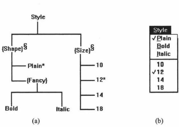
system, many special characters are used as menu and meneme modifiers. Figure 3. 15
shows the Lean Cuisine description of the reduced five meneme Style menu which has
been described using a transition network in Figure 3. 14.
Style§
L
Plain Text*L
(Fancy Text)I
Bold Italic {Indexed}
~
SuperscriptL
SubscriptFigure 3.15. The Lean Cuisine description of the reduced five meneme Style menu.
In Figure 3 .15, Style is a required choice group marked § and offers a mutually exclusive
choice between Plain Text, which is marked * as the default choice, and the virtual meneme {Fancy Text). This virtual meneme in turn represents the mutually compatible
choice of Bold, Italic and {Indexed}, the, latter another virtual meneme offering a
The Lean Cuisine notation has been used as a diagrammatic design tool to design a user interface from specification, through preliminary analysis, to the final design [Apperley, 88], and its textual form has been used as the basis for an interface prototyping environment which provides for the direct implementation of the action and control layers from a Lean Cuisine description [Anderson & Apperley, 90]. The prototyping
environment implemented by Anderson & Apperley on an Apple Macintosh provides two
software tools: the first tool generates the interface definition file (IDF) based on a Lean Cuisine textual specification and the second tool -- an interpreter then uses the interface definition file (IDF) to simulate the interface. Figure 3 .16 shows the translation of a textual Lean Cuisine specification (b) to an intermediate presentation specification ( c ). The graphical specification of the simple menu is shown in (a) and the resultant menu is shown in (d).
(Style$,M~ (Plam*, ({Fancy},MC,
(Bold, Italic, (Font,M~
(Genevh, Times)
)) )))
(b)
St~,,-le §
L
Plam*L
{Fancy}I
Bold Italic Font
(a)
t ~:::'
Style Plain (-Bold Italic Font
<
Font Gtnevt. Times
--_,.
(-(c) (d)
Figure 3.16. (a) Lean Cui~ine spec1t1cation, and (b) its translation from a textual
description to: (c) equivaient presentation model and (d) resultant menu [Anderson &
[image:39.572.85.496.318.661.2]Lean Cuisine offers a clear, concise and compact notation, wmch in its present form can be used to describe both the action and control layers of hierarchical menu systems
[Anderson & Apperley, 90], and as a graphical design tool, it is more powerful than other graphical notations (e.g. transition networks' et al.) for descriptions of complex menu systems. The specification of a menu-based user interface is much easier with the LC graphical design tool than with a te:,rtual language. If software tools are available in current graphical environments, the Lean Cuisine graphicai notation could be used as the basis for an integrated interface developing environment in which menu-based interfaces
will be very quickly built without programming.
3.5. Problems with Existing User Interface Developing Tools
Many current user interface management systems (lJIMSs) provide a set of
implementation tools, but little in the way of design aids. Most UIMSs use a textual
specification and often require the user interface designer to learn a special purpose
programming-like language, and with an ordinary text editor, it is not easy to create,
debug, and modify a textual specification file for a complex user interface. Textual
specifications are too complicated to be understand and used by non-programmers, so
these language-based UIMSs are very hard to use [Myers, 88] Very few UIMSs can
provide software tools to support user interface development from user interface design,
user interface simulation to direct implementation based on graphical description, and
support the graphical user interface development lifecycle. Existing user interface
development tools are not suitable for both interface designers and application
developers.
3.6. An Integrated Interface De,
1elopment Environment
In order to solve these problems and make user interface development much easier and
quicker, research has been carried out to develop software tools used to support the
Lean Cuisine grapmcal notation. The result of this research is an integrated interface
development environment based on Lean Cuisine graphical notation. The integrated
interface development environment is a combination of software tools used to support
user interface design, simulation and impiementation. The Lean Cuisine graphical editor
(Ek) provides an interactive design environment for graphical specifications of
menu-based interfaces. The simulation tool (Sic) provides an automatic prototype environment
diaiogue specification at any design stage by a direct mapping process. A tool called user
interface generator (Gk) is used to generate basic interface source code files for a user
interface from its Lean Cuisine graphical specification file and allows the user interfaces
to be implemented without programming. The menu-based user interface development
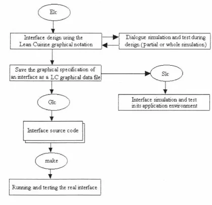
process based on these three supporting tools is shown in Figure 3 .17.
Interface design using the
I
...-1
1 Dialogue simulation and test during .___L_-_e_an_C_w_·_sir._;_e ~gr_a_p_hl_c_al_n_o_ta_b._o_n _ __,....
1 deslgn (partial or ,~rhole simulation)
Save the graphical specification of an interface as a LC graphical data file
Glc
)
Interface source code
Running and testir.ig the real interface
Slc .,./)
Interface simulation and test in its application environrnent
Figure 3.17. The menu-based user interface development process based on three
supporting tools.
The characteristic of the integrated interface development environment based on the
Lean Cuisine graphical notation is that it provides software tools which make user
interface development much easier and quicker from design and prototyping to
implementation The detaiis of three supporting tools will be discussed in following
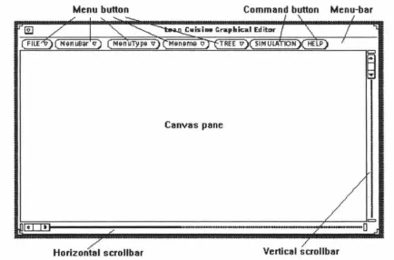
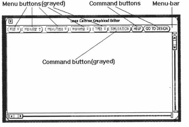
[image:41.569.81.501.171.577.2]The Lean Cuisine Graphical Editor
4.1.
Introduction
The menu interface development environment is based on the Lean Cuisine visual
notation [Apperley & Spence, 89]. Three supporting tools, Ek, Sic and Gk, have been
developed for graphical dialogue specification, simulation and automatic generation of a menu-based imerf ace. Ek is a graphical editor used by the interface designer to create a Lean Cuisine graphical description of a menu interface; Sic is a user interface simulator
and Gk is a user interface generator which can automatically generate a user interface from its Lean Cuisine graphical specification.
This chapter describes the basic structure of Ek and discusses how a menu interface designer interactively designs the graphical dialogue specification by using Ek. The user interface simulation at the design stage, and the implementation environment of Elc will also be discussed.
Before describing the basic structure and functions of Elc, it is necessary to review the
Lean Cuisine visual notation and examine an example of a Lean Cuisine description of a system of menus.
4.2.
:
Menu Structures
in the
Lean Cuisine Visual Notation
As discussed in section 3 .4 .2 .2, Lean Cuisine [ Apperley & Spence, 89] is a visual notation which can be used as a diaQramrnatic user interface desiQn ~ ~ tool. Two basic
diagrams shown in Figure 4.1 are used to describe mutually exclusive (J-from-n) menu
![Figure 2.3. The structure of the UofA * UIMS [Singh & Green, 89a].](https://thumb-us.123doks.com/thumbv2/123dok_us/8485998.343645/15.572.58.517.397.638/figure-structure-uofa-uims-singh-green-a.webp)
![Figure 2.4. Command Description for the Skeleton Editor [Singh & Green, 91].](https://thumb-us.123doks.com/thumbv2/123dok_us/8485998.343645/16.577.64.506.124.698/figure-command-description-skeleton-editor-singh-green.webp)
![Figure 3.6. The "star" lifecycle of user interface development [Hix & Hartson, 93].](https://thumb-us.123doks.com/thumbv2/123dok_us/8485998.343645/30.568.56.490.296.637/figure-star-lifecycle-user-interface-development-hix-hartson.webp)
![Figure 3.16. (a) Lean Cui~ine spec1t1cation, and (b) its translation from a textual description to: (c) equivaient presentation model and (d) resultant menu [Anderson & Apperiey, 90]](https://thumb-us.123doks.com/thumbv2/123dok_us/8485998.343645/39.572.85.496.318.661/translation-textual-description-equivaient-presentation-resultant-anderson-apperiey.webp)