UNIVERSITI TEKNIKAL MALAYSIA MELAKA
Development of Automatic Air Humidity and Temperature
Controller with Purifying Function Controlled by Arduino
This report is submitted in accordance with the requirement of the Universiti Teknikal Malaysia Melaka (UTeM) for the Bachelor of Electronics Engineering Technology
(Industrial Electronics) with Honours.
by
STUDENT NAME: CHIN ZHEN YAN MATRIX NUMBER: B071410266
IC NUMBER: 940720-07-5319
UNIVERSITI TEKNIKAL MALAYSIA MELAKA
BORANG PENGESAHAN STATUS LAPORAN PROJEK SARJANA MUDA
TAJUK:
Development of Automatic Air Humidity and Temperature
Controller with Purifying Function Controlled by Arduino
SESI PENGAJIAN: 2017/18 Semester 1
Saya CHIN ZHEN YAN
mengaku membenarkan Laporan PSM ini disimpan di Perpustakaan Universiti Teknikal Malaysia Melaka (UTeM) dengan syarat-syarat kegunaan seperti berikut:
1. Laporan PSM adalah hak milik Universiti Teknikal Malaysia Melaka dan penulis. 2. Perpustakaan Universiti Teknikal Malaysia Melaka dibenarkan membuat salinan untuk
tujuan pengajian sahaja dengan izin penulis.
3. Perpustakaan dibenarkan membuat salinan laporan PSM ini sebagai bahan pertukaran antara institusi pengajian tinggi.
SULIT
TERHAD
TIDAK TERHAD
(Mengandungi maklumat yang berdarjah keselamatan atau kepentingan Malaysia sebagaimana yang termaktub dalam AKTA RAHSIA RASMI 1972)
(Mengandungi maklumat TERHAD yang telah ditentukan oleh organisasi/badan di mana penyelidikan dijalankan)
(TANDATANGAN PENULIS)
Alamat Tetap:
9-10-12A,
TINGKAT PAYA TERUBONG 2,
AYER ITAM, 11060 PULAU PINANG.
Tarikh:___________________________
Disahkan oleh:
(TANDATANGAN PENYELIA)
Cop Rasmi:
FAKULTI TEKNOLOGI KEJURUTERAAN
Tel : +606 234 6623 | Faks : +606 23406526
Rujukan Kami (Our Ref) : Rujukan Tuan (Your Ref) :
18 JANUARI 2018
Pustakawan
Perpustakaan UTeM
Universiti Teknikal Malaysia Melaka Hang Tuah Jaya,
76100 Durian Tunggal, Melaka.
Tuan/Puan,
PENGKELASAN LAPORAN PSM SEBAGAI SULIT/TERHAD LAPORAN PROJEK SARJANA MUDA TEKNOLOGI KEJURUTERAAN ELEKTRONIK (Bachelor’s Degree in Electronics Engineering Technology (Industrial Electronics) with Honours): CHIN ZHEN YAN.
Sukacita dimaklumkan bahawa Laporan PSM yang tersebut di atas bertajuk
"
Development of Automatic Air Humidity and Temperature
Controller with Purifying Function Controlled by Arduino
.”” mohon dikelaskan sebagai *SULIT / TERHAD untuk tempoh LIMA (5)
tahun dari tarikh surat ini.
2. Hal ini adalah kerana IANYA MERUPAKAN PROJEK YANG DITAJA
OLEH SYARIKAT LUAR DAN HASIL KAJIANNYA ADALAH SULIT.
Sekian dimaklumkan. Terima kasih.
Yang benar,
________________
Tandatangan dan Cop Penyelia
* Potong yang tidak berkenaan
NOTA: BORANG INI HANYA DIISI JIKA DIKLASIFIKASIKAN SEBAGAI
FAKULTI TEKNOLOGI KEJURUTERAAN
Tel : +606 234 6623 | Faks : +606 23406526
TERHAD, MAKA BORANG INI TIDAK PERLU DISERTAKAN DALAM
DECLARATION
I hereby, declared this report entitled “Development of Automatic Air Humidity and Temperature Controller with Purifying Function Controlled by Arduino”
is the results of my own research except as cited in references.
Signature : ……….
Author’s Name : ………
Date : ………
APPROVAL
This report is submitted to the Faculty of Engineering Technology of UTeM as a partial fulfillment of the requirements for the degree of Bachelor’s Degree in Electronics Engineering Technology (Industrial Electronics) with Honours. The member of the supervisory is as follow:
i| P a g e
ABSTRAK
ii| P a g e
ABSTRACT
iii| P a g e
DEDICATION
iv| P a g e
ACKNOWLEDGEMENT
First of all, I would like to take this opportunity to express my utmost gratitude to my supervisor, Ir. Nik Azran bin Ab. Hadi for his guidance in helping me complete this project. He is selfless and sacrifice a lot of his time to provide and share with me his vast knowledge and information about this project. The time we spent together discussing the project helped to spark many ideas and points of improvement to make the project better. Therefore, here I am showing my appreciation to him for his guidance, support and encouragement.
Besides that, I would also like to show my gratitude to my faculty, Faculty of Technology Engineering (FTK) and my university, Universiti Teknikal Malaysia Melaka for providing me the education environment to nurture me as a technologist and prepare well-equipped facilities to learn. Without the nurturing and teaching of the countless lecturers during my four years at this university, I would never be able to obtain the knowledge and skills to accomplish and complete the project
v| P a g e
TABLE OF CONTENT
ABSTRAK ... i
ABSTRACT ... ii
DEDICATION ... iii
ACKNOWLEDGEMENT ... iv
TABLE OF CONTENT ... v
LIST OF TABLES ... viii
LIST OF FIGURES ... ix
LIST OF ABBREVIATION SYMBOLS AND NOMENCLATURE ... xiii
CHAPTER 1: INTRODUCTION ... 1
1.0 Introduction ...1
1.1 Problem Analysis...3
1.2 Objectives...4
1.3 Scope of Work ...4
1.3.1 K- Chart ...5
1.4 Thesis Outline ...6
CHAPTER 2: LITERATURE REVIEW ... 8
2.0 Introduction ...8
2.1 Existing Technique for Temperature and Humidity Control ...8
2.1.1 PLC based Temperature and Humidity Control. ...8
2.1.2 Fuzzy Logic Algorithm Based Temperature and Humidity Control. ...9
2.1.3 Neural Network Based Temperature and Humidity Control. ... 10
2.1.4 PID Based Temperature and Humidity Control System. ... 11
2.1.5 Summary of the case study. ... 12
2.2 Air Filtration System in Air Purifier. ... 13
2.2.1 Pre filter ... 14
2.2.2 High Efficiency Particulate Air (HEPA) Filter ... 14
2.2.3 Legionella Filter ... 15
vi| P a g e
2.2.5 Activated Carbon Filter ... 17
2.3 Motor ... 18
2.3.1 DC Motor ... 18
2.3.2 AC Motor ... 20
2.3.3 Comparison of AC Motor and DC Motor ... 21
2.4 Fan ... 22
2.4.1 Axial Flow Fan ... 22
2.4.2 Centrifugal Flow Fan ... 23
2.4.3 Comparison of Axial Flow Fan and Centrifugal Flow Fan ... 24
2.5 Arduino ... 25
2.5.1 Arduino UNO ... 26
2.5.2 Arduino MEGA ... 27
2.6 Relay Module ... 28
2.7 Pulse Width Modulation ... 29
2.8 Temperature Sensor ... 31
2.9 Humidity Sensor ... 32
2.10 DHT11 (Temperature and Humidity Sensor) ... 34
CHAPTER 3: METHODOLOGY ...37
3.0 Introduction ... 37
3.1 Project Planning ... 37
3.1.1 Gantt Chart ... 38
3.2 Project Implementation ... 41
3.2.1 Project Flowchart. ... 41
3.2.2 Hardware Selection ... 44
3.2.3 Summary of Hardware Selection ... 47
3.2.4 Types of Software ... 48
3.3 Software and Hardware Development ... 51
3.3.1 Program Flowchart. ... 53
3.3.2 Program Coding in Arduino ... 56
3.3.3 Circuit Construction in Proteus ... 64
3.3.4 Printed Circuit Board Layout Design with Proteus ... 65
3.3.5 Development of Graphic User Interface with LabVIEW ... 66
vii| P a g e
3.4.1 Voltage Measurement with Multimeter ... 68
3.4.2 Speed Measurement by using Tachometer ... 69
3.4.3 Airflow Measurement using Anemometer ... 70
3.4.4 Data Logging to Microsoft Excel by LabVIEW. ... 72
CHAPTER 4: RESULTS AND DISCUSSION ...73
4.0 Introduction ... 73
4.1 Prototype Development ... 73
4.2 Software Implementation ... 77
4.2.1 Arduino’s Integrated Development Environment (IDE) ... 77
4.2.2 Graphical User Interface by LabVIEW. ... 79
4.3 Testing and Results ... 83
4.4 Data Analysis ... 89
4.4.1 Effect of PWM on the Voltage Supplied to Fan. ... 89
4.4.2 Effect of PWM on the Speed of Fan ... 96
4.4.3 Effect of the PWM Controlled Fan Speed on the Airflow ... 103
4.4.4 Effect of the Filter on the Airflow Generated by the Fan ... 110
4.4.5 Effect of Light Bulb on the Temperature and Humidity. ... 113
4.4.6 Effect of Airflow by Fan on the Temperature and Humidity ... 116
4.4.7 Effect of Evaporative Cooling on the Temperature and Humidity ... 119
4.5 Discussion ... 124
CHAPTER5: CONCLUSION AND RECOMMENDATION ... 127
5.0 Introduction ... 127
5.1 Conclusion ... 127
5.2 Recommendation ... 128
REFERENCES ... 129
viii| P a g e
LIST OF TABLES
2.1 Range of sizes of commonly found air particles.. ...13
2.2 Arduino Board Comparison.. ...25
2.3 DHT11 pin configuration.. ...34
3.1 Hardware selection for the project. ...47
3.2 Example of the value of humidity data logged to the Microsoft Excel. ...72
4.1(a) Response of fan and light at different temperature range.. ...78
4.1(b) Response of light bulb and water pump different humidity...78
4.2 Response of the actuator at different temperature and humidity. ...79
level. ...79
4.3 Value of calculated voltage and measured voltage supplied to fan. ...93
4.4 Fan speed reading in RPM at different duty cycle. ...96
4.5 Readings Taken at 20 % Duty Cycle...97
4.6 Average, standard deviation and coefficient of variation of the three ...99
readings. ...99
4.7 Average fan speed at different voltage. ... 101
4.8 Airflow measurement at different duty cycle.. ... 103
4.9 Readings of airflow taken at 20 % duty cycle. ... 104
4.10 Average, standard deviation and coefficient of variation for the. ... 106
air flow measurement readings. ... 106
4.11 Fan speed and airflow measurement at different duty cycle and ... 108
voltage. ... 108
4.12 Airflow measurement without filter. ... 110
ix| P a g e
LIST OF FIGURES
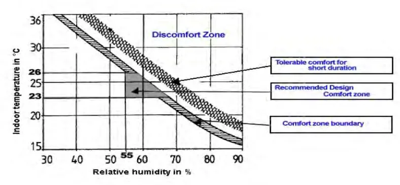
1.1 Graph of suitable thermal comfort zone (Temperature vs Humidity). ... 2
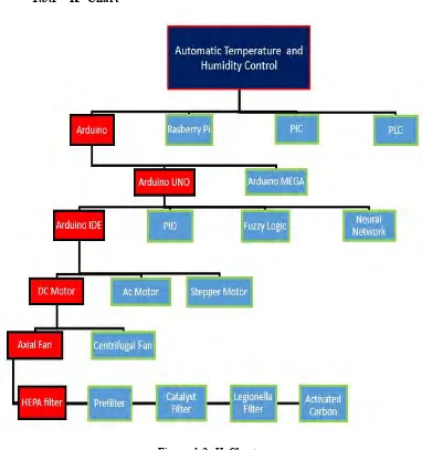
1.2 K-Chart. ... 5
2.1 Basic block diagram of the fuzzy control system. ...10
2.2 Block diagram of the temperature and humidity control. ...11
2.3 Illustration of the air particles trapped by the HEPA filter. ...15
2.4(a) Legionella filter. ...16
2.4(b) The microscopic view of the Legionella bacteria. ...16
2.5 Fleming’s left hand rule. ...19
2.6 Basic Structure of Brushes DC motor. ...19
2.7 Structure of the AC motor. ...21
2.8 Airflow through axial fan. ...23
2.9 Structure of centrifugal flow fan. ...24
2.10 Horizontal view of Arduino UNO and the port pin. ...26
2.11 Horizontal view of Arduino Mega. ...27
2.12(a) Arduino Relay Module (Front view). ...28
2.12(b) Arduino Relay Module (Back view). ...28
2.13 Pulse Width Modulation at different duty cycle. ...30
2.14(a) Structure of resistive humidity sensor. ...32
2.14(b) Structure of capacitive humidity sensor. ...33
2.15 DHT 11 sensor. ...34
2.16 Internal structure of the DHT11 sensor. ...35
2.17 Relationship between the resistance of the NTC thermistor and ...35
temperature. ...35
3.1 Gantt chart for PSM 1. ...39
3.2 Gantt chart for PSM 2. ...40
x| P a g e
3.4 Example of Arduino’s IDE interface. ...49
3.5 Basic block diagram of the project. ...51
3.6 The prototype of the temperature and humidity controller. ...52
3.7 Software Flowchart. ...55
3.8 Circuit construction in Proteus. ...64
3.9 PCB layout in Proteus ARES. ...66
3.10 Front panel of LabVIEW as Graphic User Interface. ...67
3.11 Voltage measurement with Multimeter. ...68
3.12(a) Tachometer that used for fan speed measurement. ...69
3.12(b) Fan speed measurement using photo type. ...70
3.13 Airflow measurement of the fan. ...71
4.1 Front view of the prototype. ...74
4.2 Side view of the prototype. ...75
4.3 Interior of the prototype. ...75
4.4 Back view of the prototype. ...76
4.5 Display of USB control on GUI when the system is not connect (left) and when the system is connected to Arduino (right). 4.6(a) Display of the temperature and humidity value when the system is ...80
not connected. ...80
4.6(b) Display of the temperature and humidity value when the system is ...80
connected to the Arduino and DHT 11 sensor. ...80
4.7(a) Display of the actuator response when the system is not connected. ...81
4.7(b) Display of the actuator response when the fan speed is HIGH and ...81
the light bulb is ON. ...81
4.7(c) Display of the actuator response when the fan speed is LOW and ...81
the water pump is ON. ...81
4.7(d) Display of the actuator response when the fan is OFF and the ...82
light bulb is ON. ...82
4.8 Display on GUI when the temperature and humidity level is within the ...82
preset range. ...82
4.9 Changes of the temperature and relative humidity when the system is ...83
running. ...83
xi| P a g e
4.10 Display on the GUI when the temperature is 29℃ and relative
humidity is 47%. ...84
4.11 Display on the GUI when the temperature is at 29℃ and the humidity is within preset range. ...85
4.12 Display on the GUI when the temperature and humidity is within the ...86
preset range. ...86
4.13 Display on the GUI when the temperature is at 29℃ and the humidity ...87
level is at 66%. ...87
4.14 Display on the GUI when the temperature and humidity is within the ...88
preset range. ...88
4.15 Comparison between calculated voltage and measured voltage. ...94
4.16(a) ON time, TON and OFF time, TOFF at the PWM output signal. ...95
4.16(b) ON, TON and OFF time, TOFF for 50% duty cycle. ...95
4.17 Average fan speed at different duty cycle. ... 100
4.18 Average fan speed at different supplied voltage. ... 102
4.19 Average airflow generated at different duty cycle of PWM. ... 107
4.20 Average airflow generated by different fan speed. ... 109
4.21 Average airflow with filter and without filter at different fan speed. ... 112
4.22 Testing the effect of light bulb on the temperature and humidity. ... 113
4.23 Changes of the temperature and relative humidity due to effect ... 114
of light bulb. ... 114
4.24 Testing the effect of the airflow generated by fan on the ... 116
temperature and relative humidity. ... 116
4.25 Changes of the temperature and relative humidity at LOW fan ... 117
speed. ... 117
4.26 Changes of the temperature and relative humidity at HIGH fan ... 118
speed. ... 118
4.27 Testing the temperature and humidity with the water pump and fan ... 119
turned ON. ... 119
4.28 Changes of the temperature and relative humidity at LOW fan ... 120
speed with evaporative cooling. ... 120
84
xii| P a g e
4.29 Changes of the temperature and relative humidity at HIGH fan ... 121
speed and evaporative cooling. ... 121
4.30 Comparison of temperature and relative Humidity at HIGH fan ... 122
speed and LOW fan speed with evaporative cooling. ... 122
xiii| P a g e
LIST OF ABBREVIATION SYMBOLS AND
NOMENCLATURE
AC – Alternating Current
ASHRAE - American Society of Heating, Refrigerating and Air-Conditioning Engineers
°C – Celsius
DC – Direct Current GBI- Green Building Index
HEPA - High Efficiency Particulate Air IDE - Integrated Development Environment ISCP - In-Circuit Serial Programming NTC - Negative Temperature Coefficient PID – Proportional, Integral, Derivative. PLC – Programmable logic controller PTC - Positive Temperature Coefficient PWM - Pulse Width Modulation RH – Relative Humidity
RTD - Resistance Temperature Detector
UART - Universal Asynchronous Receiver/Transmitter USB - Universal Serial Bus
UV – Ultraviolet
1| P a g e
CHAPTER 1
INTRODUCTION
1.0 Introduction
2| P a g e
Figure 1.1: Graph of suitable thermal comfort zone (Temperature vs Humidity). (L.Tan. (2008))
Therefore, this project aims to create an automatic temperature and humidity controller using sensors that can help to regulate the temperature and humidity automatically and accurately. Temperature and humidity control nowadays still needed to be manually adjusted by human power based on the comfort level of the individual. The development of this automatic temperature and humidity controller eliminates the need of constantly watching on the device to self-control the temperature and humidity of the system manually. Besides that, with the rise of global warming phenomenon throughout the world, an accurate temperature and humidity control system is highly needed to adapt to the increasing heat wave and the constant fluctuation of climate. Furthermore, in addition to that, various pollution of the nature contributes to the increasing air pollutant and harmful gaseous that are detrimental to human health. Hence, this project has taken consideration of this problem to incorporate an air filtration system into the temperature and humidity controller in order to improve the air quality in an attempt to create a clean and healthy environment.
3| P a g e
sent from the microcontroller after analyzing and processing the input data. It is a feedback system with a control loop, including sensors, control algorithms and actuators and is arranged in such a way as to regulate the variables which is the temperature and humidity at a set point. When the temperature and humidity exceeds or fall below the set point, control signal will be sent to the actuator to regulate the humidity and temperature until it returns back the set point value.
1.1 Problem Analysis
Temperature and humidity control system of the current cooling system mostly are controlled manually based on the individual comfort that may vary from one person to another. This is highly not accurate as each person's comfort zone are different from one another. Therefore, problems may arise as the temperature and humidity is not accurately controlled to provide a standardized ideal and optimum temperature and humidity for everyone. Besides that, constant fluctuation of the weather makes it difficult to constantly maintain an ideal and optimum temperature and humidity for the thermal comfort of the people.
Air cooling system like the air conditioning is ubiquitous in tropical countries such as Malaysia. With the rise of various global environmental problem such as global warming, the dependence on such cooling system increase in tandem with the increasing intensity of the heat wave from the hot climate. Without a proper control system, the usage of air the cooling system will not be regulated. This contributes to the increase of energy consumption of the household, which will be reflected on their monthly electricity bills.
4| P a g e
trend of having household pets will also affect the indoor air quality as they produce certain odor and the body hair may cause severe allergy to certain people
1.2 Objectives
The main objectives of this project are:
1. To develop an automatic temperature and humidity control system with sensors that will be able to accurately detect temperature and humidity without being affected by the constant fluctuation of the weather to maintain a constant and ideal temperature and humidity.
2. To save energy by controlling the ON and OFF state of the actuators according to the changes in temperature and humidity with accurate temperature and humidity control.
3. To improve the indoor air quality through an air filtration system that is specializes in filtering common air pollutant.
1.3 Scope of Work
The project focus on the development of the automatic temperature and humidity controller with a series of air filtration system. The project compromises of three major parts which are;
1. Detection System
5| P a g e
2. Control system
The control system consist of a microcontroller that will analyze the input data from the sensor using certain algorithms and produce a control signal to the corresponding actuator
3. Feedback System
The actuator such as the motor will produce an appropriate response to regulate the temperature and humidity based on the control signal sent from the microcontroller.
[image:24.612.137.519.272.679.2]1.3.1 K- Chart