COMMISSION OF THE EUROPEAN COMMUNITIES
Nuclear Science and Technology
THE COMMUNITY'S RESEARCH AND DEVELOPMENT PROGRAMME ON
DECOMMISSIONING OF
NUCLEAR INSTALLATIONS (1989-93)
Annual progress report 1990
EUR 14227 EN
RESEARCH PROGRAMME
Commission of the European Communities
Nuclear Science and Technology
THE COMMUNTTTS RESEARCH AND DEVELOPMENT PROGRAMME ON
DECOMMISSIONING OF
NUCLEAR INSTALLATIONS (1989-93)
Annual progress report 1990 EUR 14227 EN
Directorate-General
Science, Research and Development
Published by the
COMMISSION OF THE EUROPEAN COMMUNITIES Directorate-General
Telecommunications, Information Industries and Innovation L - 2920 Luxembourg
LEGAL NOTICE
Neither the Commission of the European Communities nor any person acting on behalf of the Commission is responsible for the use which might be made of
the following information
FOREWORD
This is the first Annual Progress Report of the European Community's 1989-1993 programme of research on the decommissioning of nuclear installations. It shows the status of implementation reached on 31 December 1990.
The Council of the European Communities adopted the programme in March 1989 III, considering: "Certain parts of nuclear installations inevitably become radioactive during operation; it is therefore essential to find effective solutions which are capable of ensuring the safety and protection of both mankind and the environment against the potential hazards involved in the decommissioning of these installations".
Also, the Council recognized that the 1984-88 programme of research on the decommissioning of nuclear installation, of which the current programme is a follow-up, "has yielded positive results and opened up encouraging prospects". The main publications relating to the results of the previous programmes are listed in Annex I.
The 1989-1993 programme covers the following areas:
A. Research and development projects concerning the following subjects: Area N° 1: Long-term integrity of building and systems;
Area N° 2: Decontamination for decommissioning purposes; Area N° 3: Dismantling techniques;
Area N° 4: Treatment of specific waste materials: steel, concrete and graphite;
Area N° 5: Qualification and adaptation of remote-controlled semi-autonomous manipulator systems;
Area N° 6: Estimation of the quantities of radioactive wastes arising from the decommissioning of nuclear installations in the Community.
B. Identification of guiding principles relating to:
the design and operation of nuclear installations with a view to simplifying their subsequent decommissioning,
the decommissioning operations with a view to making occupational radiation exposure as low as reasonably achievable,
the technical elements of a Community policy in this field. C. Testing of new techniques in practice:
pilot projects, alternative tests, staff secondment.
The research is carried out by public organisations and private firms in the Community under cost-sharing contracts with the Commission of the European Communities. The Commission budget planned for this five-year programme amounts to 31.5 million ECU.
The Commission is responsible for managing the programme and is assisted in this task by the Management and Coordination Advisory Committee "Nuclear fission energy - Fuel cycle/processing and storage of waste" (see Annex II).
-The 1989-93 programme has been started with the preparation of the four pilot dismantling projects, which concern:
the Windscale Advanced Gas-cooled Reactor,
the KRB-A Boiling Water Reactor (Gundremmingen), the BR-3 Pressurised Water Reactor (Mol),
the AT-1 fuel reprocessing facility (La Hague).
Concerning Section A, R&D Projects, and Section C, Testing of New Techniques in Practice (other than the above-mentioned pilot projects), a Call for Research Proposals was published in June 1989 /2/, with a closing date of 30 September 1989.
Upon the Call for Research Proposals, 117 proposals were submitted, many of them jointly from proposers of different Member States. As the sum of EC participations exceeded the amount of funds to be allocated by a factor of 3.5, also valuable proposals were to be rejected or reduced. After the examination, 51 proposals were selected for contract negotiation.
By 31 December 1990, 41 research contracts had been concluded - they form the subject of the present report - and 12 contracts were at the stage of negotiation. Progress achieved in 1989, the starting year of the programme, was not important enough to form the subject of a separate report and has, therefore, been included in the present report.
This first progress report, covering the period of putting the programme into action, describes the work to be carried out under contracts concluded, as well as initial work performed and first results obtained.
For each contract, the Paragraph "C. Progress of Work and Obtained Results" was prepared by the contractor, under the responsibility of the Project Leader. The Commission wishes to express its gratitude to all scientists of the contractors who contributed to this report.
The Commission staff having edited the report are: E. Skupinski, R. Bisci, K. Pflugrad and R. Wampach.
B. HUBER(*) R. SIMON(**)
References
III Council Decision of 14 March 1989 adopting a research and technological development programme for the European Atomic Energy Community in the field of the decommissioning of nuclear installations. O J N° L 98, 11.04.1989, p. 33.
ill Commission Communication concerning the research programme on the decommissioning of nuclear installations (1989 to 1993). Call for research proposals. OJ N° C 146,
13.06.1989, p. 12.
(*) Head of the Programme until January 1991. (**) Head of the Programme since February 1991.
CONTENTS
Page
1. AREA No. 1: LONG-TERM INTEGRITY OF BUILDINGS AND SYSTEMS 1 2. AREA No. 2: DECONTAMINATION FOR DECOMMISSIONING PURPOSES 2
2.1. On-line decontamination of complex components for unrestricted release,
using ultrasonic waves in a flowing aggressive chemical agent 3 2.2. Development and optimisation of an easy-to-process electrolyte for
electrochemical decontamination of stainless steel 7 2.3. Decontamination of large-volume nuclear components using foams 10
3. AREA No. 3: DISMANTLING TECHNIQUES 11 3.1. Effectiveness and long-term behaviour of cleanable high efficiency aerosol
filters 12 3.2. Abrasive water jet cutting technique from the stage of laboratory into real
application 18 3.3. Steel cutting using linear-shaped charges 23
3.4. Evaluation of the segmentation by various cutting techniques (plasma torch,
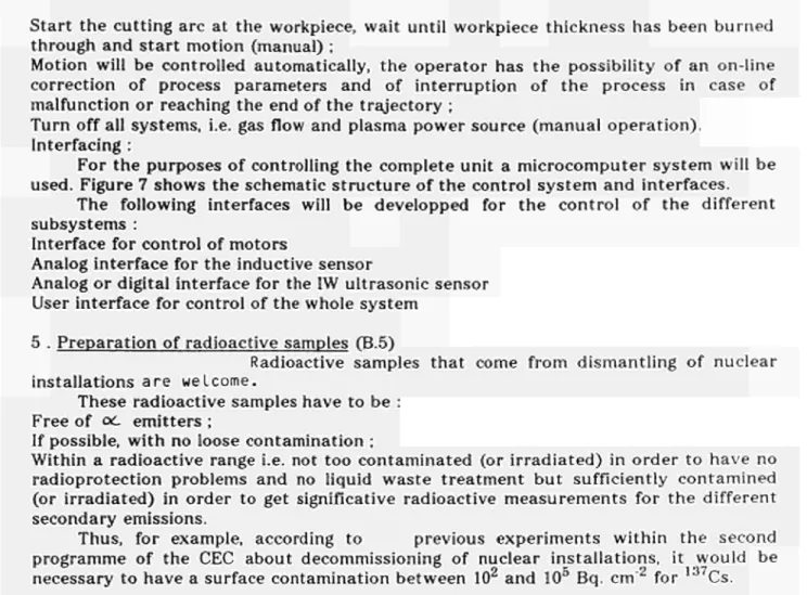
arc saw, circular disc, etc 28 3.5. Underwater thermal cutting techniques and associated remote-controlled
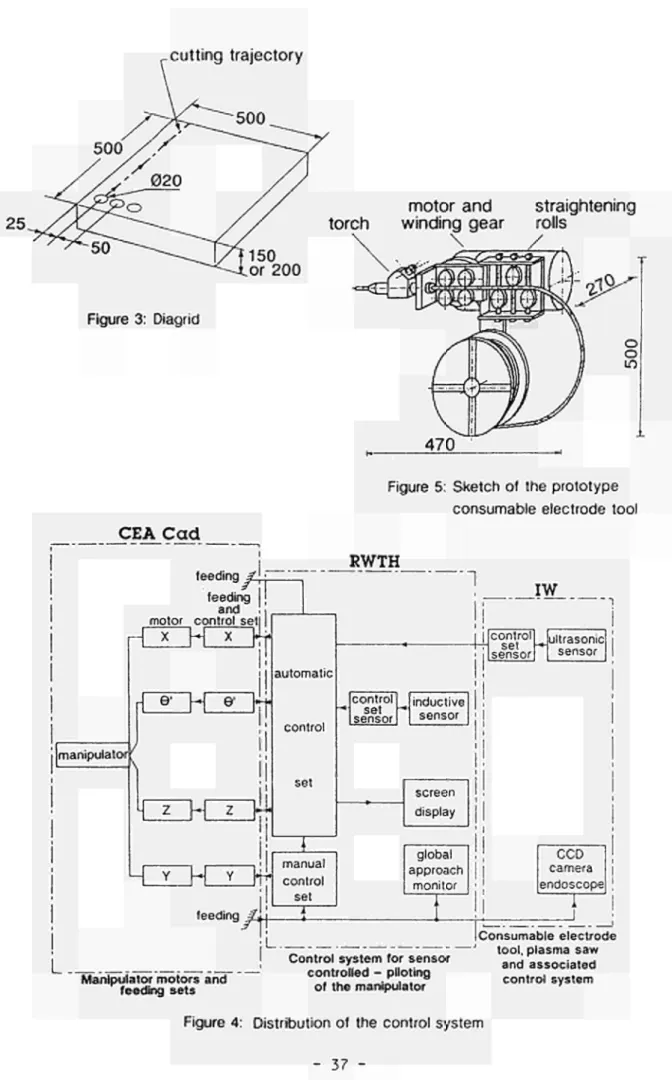
manipulator systems 33 3.6. Development of a plasma arc torch and control/monitoring technique for the
internal cutting of small bore pipework 39 3.7. Development of a steel cable to cut highly reinforced concrete with
minimised water consumption 43 3.8. Assessment of state-of-the-art CO laser technology as an improved
dismantling tool 45 3.9. Cutting of C02 primary circuit pipes of G2/G3 reactors using explosive
charges 47 4. AREA No. 4: TREATMENT OF SPECIFIC WASTE MATERIALS:
STEEL, CONCRETE AND GRAPHITE 51 4.1. Development of a process for volume reduction of contaminated/activated
concrete waste including pilot-scale testing with active waste 52 4.2. Investigations on recycling of radioactive non-ferrous aluminium and copper
by melting process 57 4.3. Recycling of activated/contaminated reinforcement metal in concrete . . . . 59
4.4. Treatment and conditioning of radioactive graphite from nuclear installations 63 5. AREA No. 5: QUALIFICATION AND ADAPTATION OF
REMOTE-CONTROLLED SEMI-AUTONOMOUS MANIPULATOR
SYSTEMS 68 5.1. Robotic system for dismantling of the process cell of a reprocessing plant 69
5.2. Design, construction and testing of a manipulator for removing slag, measuring temperature and taking samples during melting of radioactive
metal 72 5.3. Telerobotic monitoring, decontamination and size reduction system
-TMDSRS 75 5.4. Adaptation and testing of a remotely controlled underwater vehicle 79
5.5. Test of long-range teleoperated handling equipment with different tools for
concrete dismantling and radiation protection monitoring 81
5.6. Underwater qualification of RD 500 manipulator 85
-6. AREA No. 6: ESTIMATION OF THE QUANTITIES OF RADIOACTIVE WASTE ARISING FROM DECOMMISSIONING OF NUCLEAR
INSTALLATIONS IN THE COMMUNITY 87 6.1. Quick measuring methods of radionuclides in materials and wastes during
decommissioning of nuclear installations 88 6.2. Radiological aspects of recycling concrete debris from dismantling of nuclear
installations 90 6.3. Methodology to evaluate the risks of decommissioning operations on nuclear
plants 93 6.4. Definition of reference levels for exemption of concrete coming from
dismantling 95 6.5. Doses due to the reuse of very slightly radioactive steel 97
6.6. Quantification of activity levels and optimisation of dose rate management
to prepare stage 3 decommissioning of gas-cooled reactors 99 7. SECTION C: TESTING OF NEW TECHNIQUES IN PRACTICE 100
7.1. Pilot dismantling of the WAGR Phase 1: Dismantling of top bioshield
refuelling standpipes, vessel top dome; trials of remote dismantling system 101 7.2. Comparative assessment of alternative underwater remote operation and
segmenting techniques for reactor vessel internals of KRB-A 107 7.3. Pilot dismantling of the BR-3 PWR Phase 1: Decontamination of a primary
circuit, realisation of cutting equipment, segmentation of first reactor
internals 111 7.4. Pilot dismantling of the FBR-fuel reprocessing facility AT-1 Phase 1:
Dismantling of dissolution and extraction systems and of fission product
storage tanks 121 7.5. Pilot dismantling of the KRB-A BWR Phase 1 : Dismantling of contaminated
components of the reactor building and of activated internals of the reactor
pressure vessel 127 7.6. Decommissioning of the Risø hot cell facility 134
7.7. Final clean-up of the PIVER prototype vitrification facility: decontamination
of the hot cell 137 7.8. Destruction of contaminated sodium of the primary circuit of experimental
RAPSODIE reactor 141 7.9. Decommissioning of the JEN-1 experimental reactor 146
7.10. Development of segmenting tools and remote handling systems and application to the dismantling of VAK BWR reactor pressure vessel
internals 151 7.11. Melting of ferritic steel arising from the dismantling of the G2/G3 reactors
at Marcoule in a furnace installed at the dismantling site 156 7.12. Melting of alpha-contaminated steel scrap at industrial scale 158 7.13. Demonstration of explosive dismantling techniques of the biological shield
of the Niederaichbach nuclear power plant (KKN) 160 ANNEX I List of publications relating to the results of the 1979-83 programme on the
decommissioning of nuclear power plants 162 ANNEX II List of publications relating to the results of the 1984-88 programme on the
decommissioning of nuclear power plants 165 ANNEX III Members of the Management and Coordination Advisory Committee
"Nuclear Fission Energy - Fuel Cycle/Processing and Storage of Waste".. 168
-UST OF ABBREVIATIONS - CONTRACTORS' NAMES AND ADDRESSES
AEA-Culch. Atomic Energy Authority Technology Culcheth, Wigshaw Lane, UK-Cheshire WA3 4NE
AEA-Culh. Atomic Energy Authority Technology Culham, UK-Abingdon, Oxfordshire OX14 3DB
AEA-Harw. Atomic Energy Authority Technology Harwell, UK-Oxfordshire OX 11 ORA AEA-Wind. Atomic Energy Authority Technology Windscale, UK-Seascale,
Cumbria CA20 1PF
AEA-Wint Atomic Energy Authority Technology Winfrith, UK-Dorchester, Dorset DT2 8DH
BAI Benelux Analytic Instruments, Vaartdijk 22, B-1800 Vilvoorde
BE Battelle Europe - Battelle-Institut e.V. Frankfurt, Am Römerhof 35, Postfach 90 01 60, D-6000 Frankfurt am Main 90
BS Brenk Systemplanung, Heinrichsallee 38, D-5100 Aachen Bureau A+ Bureau A+, Godsweerdersingel 87, NL-6041 GK Roermond
CEA-Cad. Commissariat à l'Energie atomique, Centre de Cadarache, B.P. N° 1, F-13108 St. Paul-lez-Durance
CEA-FAR Commissariat à l'Energie atomique, Centre de Fontenay-aux-Roses, 60 Avenue du Général Ledere, B.P. N° 6, F-92265 Fontenay-aux-Roses
CEA-Sac. Commissariat à l'Energie atomique, Centre de Saclay, F-91191 Gif-sur-Yvette CEA-Valrhô Commissariat à l'Energie atomique, Centre de la Vallée du Rhône, B.P. N° 171,
F-30205 Bagnols-sur-Cèze Cedex
CIEMAT Centro de Investigaciones Energéticas Medioambientales y Tecnológicas, Avenida Complutense 22, E-28040 Madrid
COGEMA Compagnie Générale des Matières nucléaires, B.P. 270, F-50107 Cherbourg COMEX Comex Nucléaire, 36 boulevard des Océans, F-13275 Marseille
DLR Deutsche Forschungsanstalt für Luft- und Raumfahrt e.V., Pfaffenwaldring 38-40, D-7000 Stuttgart 80
ENEA Ente per le Nuove Technologie, l'Energia e l'Ambiente, Viale Regina Margherita 125,1-00198 Roma
ENEL Ente Nazionale per l'Energia Elettrica, Via R. Rubattino 54, 1-20134 Milano ENRESA Empresa Nacional de Residuos Radioactivos S.A., Calle Emilio Vargas 7,
E-28043 Madrid
ENSA Equipos Nucleares S.A., Plaza del Marqués de Salamanca, E-28043 Madrid EPC Société anonyme d'Explosifs et Produits chimiques, rue de la Dynamite,
F-13310 Saint-Martin de Crau
FHGF Fachhochschule Giessen-Friedberg, Wiesenstrasse 14, D-6300 Giessen Framatome Framatome, Tour Fiat Cedex 16, F-92084 Paris-la-Défense
KA Kraftanlagen Aktiengesellschaft, Im Breitspiel 7, Postfach 10 34 20, D-6900 Heidelberg
KEMA N.V. Keuring van Elektrotechnische Materialen, Utrechtseweg 310, NL-6812 ET Arnhem
KfK Kernforschungszentrum Karlsruhe, D-7514 Eggenstein-Leopoldshafen KRB Kernkraftwerk RWE-Bayernwerk GmbH, Postfach, D-8871 Gundremmingen
-LAINSA Limpiezas y Acondicionamientos Industriales S.A., El Payeter 13, E-46008 Valencia
NIS NIS Ingenieurgesellschaft mbH, Donaustrasse 23, D-6450 Hanau Noell Noell GmbH-Nuklear Service, Postfach 6260, D-8700 Würzburg NRPB National Radiological Protection Board, Chilton, UK-Didcot,
Oxfordshire OX11 ORQ
Radia Radiacontrôle, Route de Lyon 44, F-38000 Grenoble RNL Risø National Laboratory, P.O. Box 49, DK-4000 Roskilde
RWE Rheinisch-Westfälisches-Elektrizitätswerk AG, Kruppstrasse 5, D-4300 Essen RWTHA Rheinisch-Westfälische Technische Hochschule Aachen, Reutershagweg 4,
D-5100 Aachen
SCK/CEN Studiecentrum voor Kernenergie/Centre d'Etudes de l'Energie Nucléaire, Boeretang 200, B-2400 Mol
SG Siempelkamp Giesserei GmbH & Co, Siempelkampstrasse 45, D-4150 Krefeld 1 Siemens- Siemens AG, Bereich Energieerzeugung KWU, Hammerbacherstrasse 12-14, -KWU D-8520 Erlangen
Siemens- Siemens AG Brennelementewerk Hanau, Rodenbacher Chaussee 6, -BEW D-6450 Hanau
SSP Stangenberg, Schnellenbach und Partner GmbH, Postfach 10 28 69, D-4630 Bochum 1
Taywood Taylor Woodrow Engineering Ltd., Ruislip Road 345, UK-Southall UBI 2QX TNO Netherlands Organization for Applied Scientific Research, P.O.Box 155,
NL-2600 AD Delft
TÜV-Bay. Technischer Überwachungsverein Bayern e.V., Westendstrasse 199, D-8000 München 21
TÜV-SWD Technischer Überwachungsverein Südwestdeutschland e.V., Dudenstrasse 28, D-6800 Mannheim
UDA Universidad de Alicante, Carretera de San Vincente del Raspeig s/n, E-03099 Alicante
UH-IW Universität Hannover, Institut für Werkstoffkunde, PF 6009, D-3000 Hannover VAK Versuchsatomkraftwerk Kahl GmbH, Postfach 6, D-8756 Karlstein am Rhein
1. AREA No. 1: LONG-TERM INTEGRITY OF BUILDINGS AND SYSTEMS
A. Objective
It has been proposed that the dismantling of nuclear installations be delayed for periods ranging from several decades to about a hundred years. Thereupon, the radioactivity having largely died away, dismantling would be easier and the radiation exposure of the dismantling personnel would be less. The objective of this area is to determine the measures required for maintaining shut-down plants in a safe condition and to assess the radiological consequences of costs.
B. Research performed under the previous programmes (1979-1988) The research work has been focused on the following main subjects:
inspection of selected nuclear power plants and examination of materials as they exist therein, in order to determine the mode and pace of degradation;
methodology studies of the measures necessary for maintaining plants in safe condition and for keeping the necessary ancillary equipment operable.
C. 1989-1993 Programme
Research in this area should be pursued with a constant moderate effort, enlarging the data base and exploiting the growing experience, in order to establish confidence in long-term forecasts. This involves in particular:
collection of additional experimental data, e.g. repetition of past examinations after a time interval of about five years, in order to determine the rate of degradation and derive or check forecasting rules;
comparison of confinement methods applied at specific shut-down nuclear installations in Member States;
assessment of the merits of the Safe Storage option in the decommissioning of nuclear installations other than reactors.
D. Programme implementation
At the end of 1990, one research contract relating to Area No. 1 was at the stage of negotiation.
-2. AREA No. 2: DECOOTAMINATION FOR DECOMMISSIONING PURPOSES
A. Objective
The objective of this research is to develop and assess techniques for decontaminating surfaces of components and structures of nuclear installations that are past use. The main purpose of decontamination would be reduction of the occupational radiation exposure during dismantling of the contaminated item and/or reduction of the volume of radioactive waste.
B. Research performed under the previous programmes (1979-1988)
The following decontamination techniques have been developed and assessed: techniques using aggressive agents in liquid and gel-like form;
electrochemical techniques using various electrolytes;
hydromechanical techniques (high-pressure water lance, ultrasound); decontamination of concrete surfaces by flame jetting.
C. 1989-1993 Programme
Research in Area N° 2 should be pursued with a reduced effort focused on selected techniques. As a new subject, the use of liquid chemical agents carried by a large volume of air, in the form of foam or fog, should be developed with a view to decontaminating large-volume systems. Thermal techniques for removal of concrete surface layers should be investigated from a more general and fundamental view than in the past.
D. Programme implementation
At the end of 1990, three research contracts relating to Area No. 2 were at the stage of execution and three contracts were at the stage of negotiation.
-2.1. ON-LINE DECONTAMINATION OF COMPLEX COMPONENTS FOR UNRESTRICTED RELEASE. USING ULTRASONIC WAVES IN A FLOWING AGGRESSIVE CHEMICAL AGENT
Contractor: ENEL, Milano Contract No.: FI2D-0016 Work Period: July 1990 - June 1993 Project Manager: F BREGANI
Phone: 39/2/88 47 30 46 Fax: 39/2/88 47 39 15 or 88 47 34 96
A. OBJECTIVE AND SCOPE
Previous experiments made by ENEL on small valves, using aggressive chemicals, showed that zones with residual contamination remain inside the components.
The present work aims at solving this problem by enhancing the decontamination effectiveness with the action of focused ultrasonic waves. The main objective of the project is to set up and test in real conditions a new decontamination process based on the simultaneous use of ultrasonic waves and aggressive chemicals, with ultrasonic transducers applied outside the components.
This decontamination process, if its expected performances are confirmed, could become a useful tool in decommissioning activities. It should allow to increase the amount of decontaminable parts without having to spend many man-hours and man-rem (thus, without dismantling before decontamination).
The project is based on experimental investigations, mainly at laboratory scale but also in plant scale. It is the continuation of work performed by ENEL in the framework of previous EC programmes on decommissioning (contract DE-B-005, report EUR 9303; contract FI1D-0002, report EUR 12878).
B. WORK PROGRAMME
B.l. Evaluation, selection and acquisition of special ultrasonic transducers to be applied to complex components from outside.
B.2. Decontamination tests on specimens and components in the DECO loop.
B.2.1. Preparation of the DECO loop for testing; selection and characterisation of test specimens and components from Garigliano BWR.
B.2.2. Decontamination tests on contaminated specimens.
B.2.3. Decontamination tests on valves: radioactivity measurements, decontamination factor evaluation and secondary waste assessment.
B.2.4. Data analysis.
B.3. Decontamination and dismantling of a part of a real system of a nuclear power station B.3.1. Preparation of the system part to be decontaminated.
B.3.2. Initial radioactivity characterisation. B.3.3. Process design and configuration. B.3.4. Decontamination.
C. PROGRESS OF WORK AND OBTAINED RESULTS Summary of main issues
The development of a new type of transducers which can be applied on the external surface of components of various geometry and thickness (e.g. valves, piping, fittings, etc.) has been started.
The type of transducers and wave generators to be used have been identified and their main design parameters have been defined. The executive design and the construction phases are in progress.
Progress and Results
1. Evaluation, selection and acquisition of special ultrasonic transducers (B.l.)
The ultrasonic transducers to be developed should basically meet these requirements: - they should be applied on the external surfaces of components such piping of various
diameters and thickness, fittings, valves etc.;
- they should be able to supply an high intensity ultrasound field inside the components above indicated; therefore the frequency and power of the ultrasound field should be varied as a function of the different operating parameters (e.g. component geometry and thickness).
Specifically for starting the present study, the following design parameters are considered:
- the transducers should be coupled to piping with a diameter ranging between 35 and 105 mm;
- the tubing thickness ranges between 5 to 20 mm;
- the power supply from the transducer inside the piping should be 300 W as a minimum and can be varied in a wide range;
- the ultrasound frequency should be between 20 to 40 kHz.
A market research, however, has evidenced that the transducers currently available do not meet contemporary all the requirements above indicated. As an example, high power commercial transducers are extensively used for metal surface working; however, in this application, the ultrasound transmission beyond the material surface is unimportant. Therefore key issues such as the determination of the characteristic resonance frequencies of the material in various working conditions are not commonly addressed.
Consequently the development of this new type of transducers requires a preliminary design study that has been committed to an ultrasonic laboratory which has developed a valuable experience in this field.
Specifically the design phase will address the following: - simulation and design of the transducer and its coupler; - simulation and design of the wave generator;
- coupling and calibration of the wave generator and the transducer.
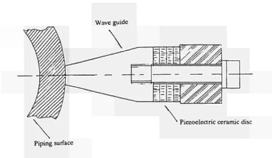
The transducer will be of the Langevine type (e.g. precompressed) it basically consists (Fig. 1) of a piezoelectric ceramic material disc forced between two metallic blocks, it employs a conic wave guide to focus wave beam. The coupling to the piping surface will be made with an epossidic resin.
The optimum design configuration of the transducer will be defined by a computer study. Specifically the analysis of the equivalent loop of a piezoelectric transducer will be performed in order to define the working frequency which determines the highest coupling efficiency.
Similarly the design of the wave generator requires a computer modelling study (PS
-pice programme). This program allows to evaluate the transducer impedance changes as a function of the different operating conditions. Moreover it simulates a coupling transformer which minimizes the impedance changes.
As a basis for the computer study the electric loop of a generator able to supply 3500 W either at 23 or at 40 kHz will be used.
An example of the study performed is shown in Fig. 2 where the calculated voltages as a function of the resonance frequencies in various transducer points are plotted. It can be noted that the lower voltages, e.g. the maximum coupling efficiencies, are obtained at a frequency of 22 kHz approximately.
Wave guide
'€£¡£a
Piezoelectric ceramic disc Piping surface
Figure 1 - Schemes of a piezoelectric transducers with a conic wave guide.
Date/Tlee run: 12/ÏO/90 09:59:39 2.4fi +
2.0A +
TRASDUTTORE 2 0 - 2 2 - 2 4 KHZ
l . C O f
T e m p e r a t u r e : 2 7 . 0 ■+
I USO) ■ I (LSI) <· KLS2) ♦ I (VI)
Frequency
Figure 2 - Example of computer simulation studies. The calculated voltages vs. the resonance frequencies.
-2.2. DEVELOPMENT AND OPTIMISATION OF AN EASY-TO-PROCESS ELECTROLYTE FOR ELF.CTROCHFMICAL DECONTAMINATION OF STA1NT.RSSSTP.RI.
Contractor: KA, Heidelberg Contract No.: FI2D-0020 Work Period: July 1990 - June 1992 Project Manager: A STERINGER
Phone: 49/6221/39 42 50 Fax: 49/6221/39 47 07
A. OBJECTIVE AND SCOPE
This work aims at optimising an acetyl-acetone base electrolyte so that it can be used for electrochemical decontamination of stainless steels. Kraftanlagen Heidelberg developed the electrolyte under the preceding EC programme from 1984 to 1988, (contract No. FI1D-0004, report EUR 12383).
With regard to waste management and disposal, the obtained electrolyte came up to all expectations. An advantage of the organic electrolyte as compared to the phosphoric/sulphuric acid electrolyte is its long radiological service life (the activity settles out continuously). It is easy to convert the crystalline by-product (sediment) by high-pressure compaction into a form that is suitable for disposal. As only little residues of acetyl-acetonates are dissolved in the electrolyte, it is possible to considerably reduce the electrolyte volume by evaporation.
In tests with radioactive samples of carbon steel, the obtained results concerning removal effects, duration of treatment, surface quality, and decontamination factors, were satisfactory or good. However, pitting was stated in the tests with samples of stainless steel. As a consequence, the surface was not uniformly removed. Parts of the original surface were visible for a long time. This resulted in poor decontamination factors or long treatment times, respectively. In addition, larger volumes of secondary wastes were produced than with a uniformly removed surface. It is therefore required to optimise this electrolyte, if it is to be used for the treatment of stainless steel.
B. WORK PROGRAMME
B.l. Quantitative investigations concerning the dissolution mechanism
B.2. Optimisation of the aqueous electrolyte through replacing the potassium bromide by other conductive salts.
B.3. Investigations into scattering and its effect on abrasion, surface quality and decontamination factor.
B.4. Development of a water-free electrolyte.
C. PROGRESS OF WORK AND OBTAINED RESULTS Summary
Essentially, the analytical testing and practical experiments to develop a new electrolyte occur simultaneously. Only when the tests of dissolution mechanisms have been concluded, can the work of substituting the potassium bromide through other conductive salts, the examination of the scatter behaviour and the influence on removal efficiency, surface quality, decontamination effect and the development of a non-aqueous electrolyte be assessed.
There were many conductive salts that showed positive results. Satisfactory removal rates along with a good anode current yield could be achieved. It should be possible to improve the results through optimizing various parameters. A modified viscosity did not affect the electrolyte scattering, and the removal efficiency.
The investigations aiming at the development of a non-aqueous electrolyte are not to be restarted before completing positive tests with the aqueous electrolyte.
Progress and Results
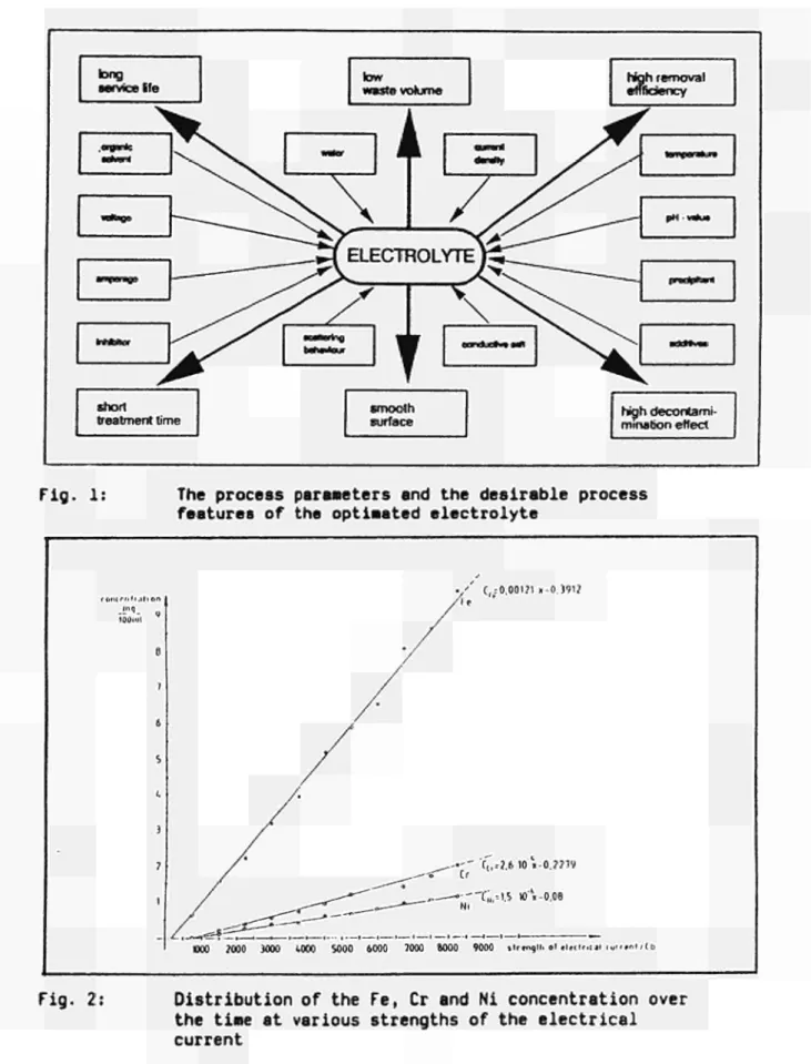
In the course of this project, an electrolyte on the basis of acetylacetone is to be optimized, for use in the electrochemical decontamination of stainless steels. Figure 1 shows the lists of the process parameters and the desirable process features of the easy-to-process electrolyte.
1. Quantitative investigation concerning the dissolution
In order to exclude selective dissolution mechanisms phases, it is necessary to determine the quantitative dissolution of the alloying constituents, dependent on the time of treatment. To review local corrosion, the corrosion current is measured.
The investigations of the dissolution mechanism are supported by galvanostatic and potentiostatic measuring methods.
1.1. Results to date
First investigations of the dissolution mechanisms showed that the metalion concentration corresponds at any point of time to the percentage of the stainless steel alloying constituents. The concentration of Cr, Ni and Fe, throughout the test time and at various strengths of the electrical current, is specified in Fig. 2.
Despite pitting, there were no signs of a selective dissolution of the various alloying constituents.
There are certain indications that, in the presence of inhibitor anions, the anodes are dissolved by halides, without any pitting.
1.2- Perspectives
The investigations of the selective dissolution mechanism should be continued.
Further investigations to analyse the influence of inhibitors on the pitting behaviour of specific anions at the anode.
The results obtained in the tests are to be compared to the tests described in the relevant technical literature.
2 Optimisation of aqueous electrolytes through replacing the potassium bromide by other conductive salts
This step is to investigate various measures that are likely to reduce or entirely eliminate the aqueous electrolyte's tendency to pitting. To this end new conductive salts are being investigated as a KBr replacement.
In addition, it is aimed at finding inhibitors which prevent pitting, and with the high removal rate remaining unchanged.
2.1. Results to date
Out of a great number of possible conductive salts and mixtures thereof used to replace KBr, satisfactory and even very good results were obtained in the test below. The results are shown in Table 1.
-2.2. Perspectives
The positive effect of the various conductive salts and mixtures thereof remains to be analysed. The results obtained were checked for a possible solid separation in the form of the Me+n (acac)n which depends on the pH value. Moreover, the electrolyte service life must
be investigated in more detail.
The results obtained during the investigation of the dissolution mechanism and the relevant factors will greatly influence any further steps in the development of an electrolyte where KBr is replaced by other conductive salts. The first results are expected by about mid-1991. 3. Investigations of scattering behaviour and the effects on removal efficiency, surface quality
and decontamination factors
This step is to investigate the effect of viscosity on the scattering power and removal efficiency of the new aqueous and non-aqueous electrolytes. The respective tests are to accompany electrolyte development.
3.1. Results to date
To the electrolytes on the basis of acetylacetone containing KBr, CaCl2 and FeCl3, gelatin
and polyglycol was added in order to increase the viscosity. No effect on the scattering power and removal behaviour was determinable.
3.2. Perspectives
The tests will be continued only when the other work packets promise no success. 4. Development of a non-aqueous electrolyte
An electrolyte is to be developed in which the water is entirely replaced by an organic solvent, in order to preclude pitting.
4.1. Results to date
In this test series, the water was replaced by methanol. During the tests, the anode current yield lay from 89 to 94 %, whereas the thickness losses were between 50 and 75 % with removal rates of 1.5 - 3.4 micron min"1. Methanol must be added from time to time, to make
up for the evaporation losses. The service life of the electrolyte based on MeOH is extremely short.
4.2. Perspectives
Tab. 1
Results of the different conductive salts used to replace KBr
conductive salt
Na2504
CaCl2
FeCl3 +
CrCl3 +
CaCl2
TBA-Br
KH2PO4 +
Na2S04 +
Ethanolamin
KH2PO4 +
Na2504
Na2S04 +
KH2PO4 + Ethylendiamin
KH2PO4 +
Na2S04
Ethanolamin
KBr
anode current
yield %
40
96,5
108
< 90
55 - 100
57 - 59
66
67 - 73
removal rate μιη min~l
1,6 - 2,59
2,13
3,86
> 1,5
0,05 - 0,57
0,17 - 0,33
0,38
0,28 - 0,48
remark
smooth surface
smooth surface
with shallow dimples
smooth surfece with a cavity
short service life removal rate
decreased continually
good - very good
very good
very good
good
-long service Ife
•CeVorrt
« « ■ Β «
. * * >
« —
tow
waste volume
M k r
short treatment time
A
i
\
«anni
high removal effnciency
/ / ^
ELECTROLYTI
ν ι ν
' /
M i w t o u r
i
τ
Λ^Ρ—
-^
~/3^z
—*——
\ N
eonoucvw M
smooth surface
^ ^ .
p H - « * N
pradpltant
■üuHii«
high decontami minabon effect
Fig. 1: The process parameters and the desirable process features of the optimated electrolyte
f (UK r n tr . i l i ort
- f i . g
ΙΟύπιΙ 0 7 6 5 ι. 3 ? 1 -/.
/ í i S í ^ »οο ?οοο 3000
. / ' C, =0 00171 χ-0.3912
At
' /
/
/
. · ' C,,.2.6 10Λ0.??79
^^—S^ Cr
^^~^°^ * ——"ti,» 1.5 »Λ0.06
1000 5000 6000 7000 6000 9000 »irmo.il. of «l.cl».cii luff» it Hb
Fig. 2: Distribution of the Fe, Cr and Ni concentration over the time at various strengths of the electrical current
-23. DEæNTAMMATION OF LARGEVOLUME NUCLEAR COMPONENTS USING FOAMS
Contractors: CEA-Cad, AEA Winf Contract No.: FI2D-0035
Work Period: October 1990 - March 1993 Coordinator: J Ρ GAUCHON, CEA-Cad
Phone: 33/42 25 61 93 Fax: 33/42 25 35 45
A. OBJECTIVE AND SCOPE
There are only a few methods for in-situ decontamination of very large components usually in complex forms, such as large valves, reservoirs, heat exchangers, turbines, vessels, boilers.
The foam application processes have the major advantage of using only small quantities of liquid and being able to forcefully penetrate everywhere. Suitable chemical reagents are added to the foam, which acts a dynamic carrier.
In this contract, a technique of permanent foam circulation will be sought, so that decontamination can last for several hours in order to be as effective as possible and to use only a minimum amount of liquid. Decontamination factors of over 100 are expected.
The objectives of the programme are to:
develop and demonstrate an effective in-situ decontamination technique for large-volume components using chemical foams containing decontamination reagents;
minimise the volume of secondary wastes produced and demonstrate a treatment and disposal route, e.g. electrolytic processes, wet oxidation.
B. WORK PROGRAMME
B.l. Chemical foam formulation containing decontamination reagents (AEA and CEA) B.2. Foam production and development of a circulation system (AEA and CEA) B3. Small pilot tests to qualify the decontamination method (CEA)
B.4. Secondary wastes treatment (AEA)
B.5. Design, construction and operation of a prototype foam production and circulation rig: non radioactive demonstration (AEA and CEA)
B.6. Industrial application by radioactive tests on a 25 m3 contaminated vessel from Winfrith
Steam Generating Heavy Water Reactor (AEA)
C. PROGRESS OF WORK AND OBTAINED RESULTS
No significant work was performed in this just starting contract.
3. AREA No. 3: DISMANTLING TECHNIQUES
A. Objective
The objective of this research is the development of the special techniques needed for dismantling the large steel components (e.g. reactor pressure vessel) and reinforced-concrete structures (e.g. reactor shielding) of redundant nuclear installations, account being taken of the particular requirements due to radioactivity.
B. Subjects of the research performed under the previous programmes (1979-88) The following main dismantling techniques were developed and tested:
thermal techniques such as plasma-arc and oxygen cutting and cutting by laser beam; mechanical techniques such as abrasive water jet cutting;
explosive techniques for the dismantling of concrete structures.
C. Programme 1989 to 1993
Research in this Area should be pursued vigorously with particular respect to the: development of the arc-saw technique for cutting thick-walled steel components; further development of the electrolytic technique for segmenting thick steel sections; comparative assessment of various segmenting techniques with reference to standard cutting tasks;
full-scale testing of controlled explosive techniques for dismantling of concrete and metal structures.
D. Programme implementation
At the end of 1990, nine research contracts relating to Area No. 3 were at the stage of execution and two contracts were at the stage of negotiation.
-3.1. EFFECTIVENESS AND LONGTERM BEHAVIOUR OF CLEANABLE HIGH EFFICIENCY AEROSOL FILTERS
Contractor: TÜV Bayern Contract No.: FI2D-0007
Work Period: July 1990 - June 1992 Project Manager: Ρ BOEHM, TÜV Bayern.
Phone: 49/89/519 01 65 Fax: 49/89/519 02 80
A. OBJECTIVE AND SCOPE
Because of the high quantity of dust generated by various cutting/dismantling processes, frequent replacement of high-efficiency sub-micron particulate air filters is necessary. If such filters could be cleaned during service, costs for the replacement of the filters, radiation exposures and the amount of secondary waste could be reduced.
The effectiveness in long-term operation (approx. one year) of high-efficiency submicron particle air filters will be investigated in the framework of the dismantling of the Niederaichbach nuclear power station (KKN) in Germany.
A high-efficiency submicron particle air filter system will be exposed to heavy dust generation during the remote-controlled dismantling of KKN primary circuit pressure tubes, and therefore must be dedusted periodically. The dust is radioactively charged (essentially Co-60 and Fe-55). The radioactivity could amount to approx. 1.10.5 Bq/g (pressure tubes and moderator tank)
and the dose rate to 0.1 Sv/h. There is at present no experience on the effectiveness and the long-term behaviour of high-efficiency submicron particle air filters that are dedustable during operation.
B. WORK PROGRAMME B.l. Installation of the filters
B.2. Determination of the main parameters of the clean filter station
B.3. Continuous measurements (pressure pickups, air humidity and temperatures) during cutting of KKN primary cooling circuit (activated cooling channel tubes inside the reactor vessel) B.4. Final evaluation including radiation exposure of workers, secondary waste arisings, specific
C. Progress of Work and Obtained Results
Summary
Putting the filter plant with cleaning equipment into operation was completed in November 1990. The measuring instruments for measuring the pressure differences of the high efficiency aerosol filters (S-filters) were installed in December 1990. Remote-controlled dismantling in the KKN commenced in January 1991. Measuring instruments for measuring relative air humidity and the temperature of clean air are currently being installed.
Progress and Results
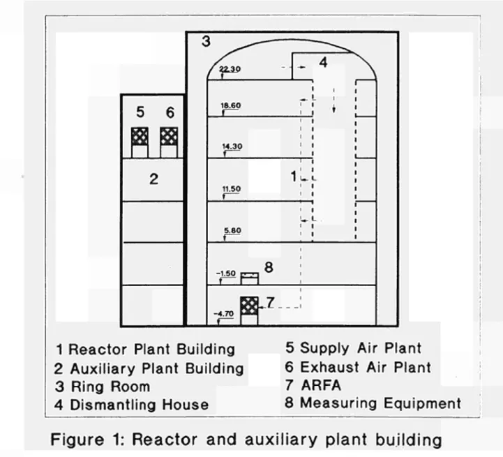
The room ventilation plant in the Niederaichbach nuclear power plant consists of a supply air plant and various exhaust air plants.
In order to retain radioactive dust particles, the exhaust air is conducted through a filter plant with two filter stages (HFA). Both filter stages contain high efficiency aerosol filters. The filtered exhaust air is discharged into the environment through an outgoing air flue. The maximum exhaust air flow rate is 110,000 m3/h.
During remote controlled dismantling the exhaust air flow contains a high percentage of dust particles. This exhaust air flow is additionally sent through a filter plant with cleanable filters. This filter plant contains a filter stage with high efficiency aerosol filters.
This means that during remote controlled dismantling, the exhaust air volume flow, with its high dust particle content, is conducted first through the filter plant with the cleanable filters (ARFA), then through the filter plant with the two aerosol filter stages.
The maximum exhaust air volume flow through the ARFA is 30,000 m3 /h.
The ARFA consists of six filter bank housings, each containing five filter bank units. Each filter bank unit has shut-off valves on the dust air side and on the clean air side. The shut-off valves on the clean air side are closed automatically when the ARFA is not running.
In each of the thirty filter bank units is a filter box with a high efficiency aerosol filter.
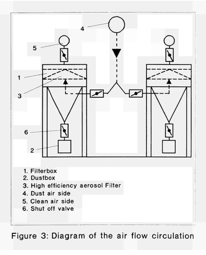
The flow circulation of the exhaust air being filtered is shown in the schematic representation of the plants (figures 1, 2 and 3).
The aerosol filters are cleaned with compressed air. Blast air supports moved by compressed air cylinders are moved back and forth along the entire width and length of the aerosol filters.
The compressed air emitted from the blast jets of the support blows the dust particles accumulated in the aerosol filters into dust boxes. The compressed air requires a maximum operating pressure of 6 bar.
The aerosol filters and blast jet supports can be inspected through windows in the filter bank housings.
An operating unit monitors the pressure differences
-of the aerosol filters, using the pressure difference to control cleaning.
Only two aerosol filters are cleaned at any time. The shut-off valves on the clean air side are closed
automatically during this process.
The starting period of the ARFA involved the following measurements and tests:
- Measurement of the supply and exhaust air flow rates. - Measurement of the pressure differences at the clean
aerosol filters.
- Measurement of the pressure in the reactor building and in the dismantling house.
- Measurement of the static pressures on the suction and pressure sides of the ventilators.
- Measurement of the temperatures and relative humidity of the supply and exhaust air flows.
- Leakage test on the filter bank housing.
- Leakage test on the shut-off valves on the clean air side.
- Leakage test of the sealing band of the filter boxes on the dust air side.
- Visual check of the function of the blast jet supports for cleaning the aerosol filters.
- Measurement of ventilator speed.
- Test of electrical locking functions. - Test of fault indication.
There has been no automatic cleaning of the S-filters so far. Due to the dismantling schedule of KKN, increased dust in the waste air is not expected until mid-1991 (the beginning of the dismantling of the Moderator-Tank by grinding).
5
6
R
a
2
3
^
(123$ *
18.60 ï*"
14.30 '
iL
11.50
5.80 |
4 ^
ι 1
L .
1
Q
-i-so p q σ ι
-4.70 B i
^Z___
1
1 Reactor Plant Building
5 Supply Air Plant
2 Auxiliary Plant Building
6 Exhaust Air Plant
3 Ring Room
7 ARFA
4 Dismantling House
8 Measuring Equipment
Figure 1: Reactor and auxiliary plant building
Max. 110,000 m3/h
max 30,000 m7h
> H Z r
-4
5 2
- H Z -
—E~|
/ '
! J
\ ,
1. Fan
2. Main filter plant (HFA)
3. Radial Fan with two Motors
4. Filter plant with cleaning equipment (ARFA)
5. S-filter
6. shut off valve
o
I
1. Filterbox
2. Dustbox
3. High efficiency aerosol Filter
4. Dust air side
5. Clean air side
6. Shut off valve
Figure 3: Diagram of the air flow circulation
3.2. ABRASIVE WATER JET CUTTING TECHNIQUE FROM THE STAGE OF LABORATORY INTO REAL APPLICATION
Contractors: UH-IW, CEA-Sac Contract No.: FI2D-0009 Work Period: July 1990 - June 1992 Coordinator: H LOUIS, UH-IW,
Phone: 49/511/762 4320 Fax: 49/511/762 3456 A. OBJECTIVE AND SCOPE
In order to qualify the cutting by abrasive water jets for application in contaminated or activated environment, the cutting techniques developed for laboratory application (CEC contracts FHD-0069 and FHD-0067) are to be adapted for remote-controlled application. Secondly, concepts for the handling of the secondary waste are to be developed and proved.
First, the existing abrasive cutting head is to be adapted to remote-controlled work under a water shield up to 15 m, in an inaccessible environment. For this application, methods have to be implemented and proved to control the cutting operation, for instance the state of wear and the cutting results (e.g. depth of the kerf, cutting through). Additionally, parts showing wear are to be remotely replaced so as to allow long-term reproducible operation.
The second step concerns investigations on the secondary waste. Besides a calculation of the composition and amount of secondary waste depending on cutting parameters, strategies will be developed and tested to catch the waste as close as possible at the place of production. Filtration techniques to separate abrasives and cut material from water and air will be adapted from other cutting techniques and will be tested.
All tests will be carried out under non-radioactive conditions, but at real scale in special water basins. The aim of this research work is to set up a tool which is suitable for work under realistic conditions. A control system and the remote replacement of worn parts are further important aims of this research work.
B. WORK PROGRAMME
B.l. Definition of cutting parameters for decommissioning purposes (UH-IW)
B.2. Development of controlling systems for processes parameters and the cutting result (UH-IW)
B.2.1. Preparation of a two-dimensional feeding mechanism for underwater cutting tests. B.2.2. Development of an on-line controlling system to detect the state of wear inside the
cutting head.
B.2.3. Development and adaptation of controlling methods to verify the cutting result during or just after cutting.
B.2.4. Design of a cutting head which includes controlling systems, cutting tests to qualify the sensor systems.
B3. Development of methods to remotely replace worn parts of the cutting head under water (UH-IW)
B.4. Characterisation and handling of secondary waste
B.4.1. Preparation of test facilities for measuring aerosols and suspended particles when cutting in air and under water (UH-IW).
B.4.2. Measurement and characterisation of the secondary emissions when cutting or kerfing in air or under water (CEA).
B.4.3. Development of methods to lower the spreading out of emissions in air or under water (UH-IW).
C. PROGRESS OF WORK AND OBTAINED RESULTS Summary of main issues
In the first period parameters have been fixed for abrasive water jet cutting for decommissioning purposes. Special demands on the cutting technique like underwater applicability because of radiation protection and minimisation of waste must be noticed. To reach an optimal cutting efficiency regarding water and abrasive consumption it is useful to work on a high pressure level with a small nozzle diameter.
For dismantling jobs a remote-controlled operation is necessary, therefore sensor systems are required to supervise the tool function and the cutting result. A water basin was built to test sensor equipment. A method was found to control the diameter of the focusing nozzle
(increas-ing by wear) by measur(increas-ing the sucked-in air flow.
Further tests will be carried out to optimise the method of noise analysis for controlling the cutting result.
Progress and results
1. Definition of cutting parameters (B.l.)
For the application of abrasive water jets in contaminated environ-ment the reduction of secondary waste is very important. So cutting param-eters are useful which are quite different from "normal" industrial appli-cations. Additionally also the use of the tool under water creates special demands on the cutting technique regarding the sensitiveness against changing the working distance, for example.
Results from contract FI1D-0069 /ref. 1/ have shown that there is an optimal nozzle size to reach the best cutting efficiency regarding the used amount of water. This efficiency increases with increasing water pressure. Fig. 1 shows the optimal nozzle diameter for a water pressure of 2400 bar. The optimal nozzle size is 0.2 mm, increasing the diameter effects a decrease in cutting performance related to the used water flow rate /ref. 2/.
A similar effect is given for the abrasive flow rate. Increasing the flow rate effects an increase in cutting depth. But when this cutting depth is related on the used abrasive flow rate, there is an optimal flow rate at very low rates (fig. 2). Using for example only 2 g/s for a cer-tain cut means the lowest production of abrasive waste, but the cut lasts longer than using a higher abrasive flow rate.
For the application in contaminated environment it is necessary to cut under the protection of a water shield. In that case the abrasive water jet is sensitive against the variation of the working distance. Fig. 3 gives the results of cutting tests comparing application in air and under water. The momentum loss under water is only small when using a short nozzle-sample distance. For distances about 25 mm there is only half the cutting performance than using 2 - 5 mm distance. This effect results in high demands on the handling system and the sensor system to keep and
-control the working distance.
2. Development of controlling systems (Β.2.)
2.1. Preparation of a twodimensional feeding mechanism
An existing feeding mechanism had to be modified to carry out two
dimensional cutting tests with abrasive water jets under water. So a water
basin was modified which allows the testing of sensor systems to detect
the cutting result (cutting through or kerfing). Twodimensional cutting
tests are necessary to check the effect of changing the cutting direction
on the sensor signals.
Additionally this equipment allows to filter the water and to ana
lyse the suspended particles. Tests will be carried out together with CEA
Saclay to quantify the amount of waste (B.4.).
2.2 Development of an online controlling system to detect
the state of wear inside the cutting head
When operating in inaccessible environment it is necessary to con
trol the state of the tool. In the case where undue worn parts have to be
removed water jet nozzle and focusing nozzle especially have to be con
trolled to reach a sufficient cutting efficiency at every time.
The wear of the water jet nozzle can be supervised by measuring the
water flow rate. In case of wear or chipping the water flow rate increases
when the pressure is constant.
The wear of the focusing nozzle can be calculated by controlling the
air flow rate suckedin by the injection cutting head. Fig. 4 shows the
effect of the focusing diameter on the air flow suckedin. To measure this
air flow rate a flow meter is necessary in the transportation tube of the
abrasives. So the abrasives have to pass the flow meter together with the
air where it will be causing wear.
Otherwise the abrasives can be stored in a closed vessel and the air
suckedin in this vessel can be measured.
On the other hand the flow rate and so the diameter of the nozzle
can be calculated by measuring the pressure drop in the transportation
tube. This method is very easy to realise: Two pressure sensors are adapt
ed in different positions of the transportation tube, the pressure drop is
proportional to the flow rate.
References
HI Haferkamp, Η.; Louis, Η. and Meier, G.:
"Weiterentwicklung des AbrasivstrahlSchneidverfahrens zum Trennen
ferritischer und austenitischer Stähle unter Wasser", EUR 12684 DE
121 Haferkamp, H.; Louis, H. and Meier, G.:
"Submerged Cutting of Steel by Abrasive Water Jets"
Proc. of the 1989 Intern. Conf. on Decommissioning of Nuclear Instal
■cr
^Ε
15000-E CU o σ E Q . σ> c: r j 10000-<υ σ
g
5000-M—
CU o
3= Ο
Ι
I ι ι ι ι ι ι
) 0.1 0.2 0.3 nozzle diameter in mm
pressure: 2400 bar traverse rate:
100 mm/min distance: 2 mm material: AIMgSi0.5 «v abrasive: garnet
optimal abrasive tiow rates optimal focusing
nozzle sizes
1 1 1
0.4 0.5
Figure 1 Effect of water flow rate on cutting efficiency
en C N E E cu CJ σ E Ι Ο t : CU C L CD C CU ■> "c/i σ 1— σ 16 14 12 10 8 6 4 2 0
pressure: 2400 bar
nozzle diameter: 0.25 mm focusing nozzle: D = 1.2 mm
L = 50 mm traverse rate: 100 mm/min distance: 2 mm
material: AIMgSi0.5 abrasive: garnet
i — | — ι — ι — ι — ι — ι — | — ι — I — ι — I ' Ι ι I ' I r Ί — ' — I — ' — Γ
0 2 4 6 8 10 12 14 16 18 20 22 24
abrasive flow rate in g/s
Figure 2 Effect of abrasive flow rate on cutting efficiency
50
E 40 -E
30 -cu
o 20
-CL·
CU
-υ 10
in air
ι 10
under water
I
20 - r ~ 40
pressure: 3000 bar nozzle diameter: 0.25 mm focusing nozzle: D = 1.4 mm
L = 50 mm traverse rate: 100 mm/min material: AIMgSi0.5
abrasive: garnet, 8 g/s
50
30 40 50 60
nozzle sample distance in mm
70 80
Figure 3 Effect of nozzle-sample distance on depth of kerf
jz 3Ί
f O E2 . 5
"S 2
-σ '·
flo
w
ι
'5 1
-^ -^ *
^ ^ pressure: 2400 bar
^ ^ nozzle diameter: 0.25 mm
/ focusing nozzle: L = 50 mm
/ tests under water
ι ι ι ι I I
1 1.2 1.4 1.6 1.8 2 diameter of the focusing nozzle in mm
33. STEEL CUTTING USING LINEAR-SHAPED CHARGES Contractor: OTO MELARA
Contract No.: FT2D-0010 Work Period: July 1990 - June 1993 Project Manager: G PEZZICA,
Phone: 39/187/40 91 28 Fax: 39/187/42 10 26 A. OBJECTIVE AND SCOPE
Various types of cutting charges already exist, but mainly for cutting of few millimetres thick material.
The research work will therefore focus on the development of a high performance cutting charge minimising the damages to surrounding structures for the dismantling of thick-walled steel components (ranging between 10 to 250 mm thickness), e.g. pipes, reactor pressure vessels. The work will include studies and experiments at small and large scale, as well as a study to possibly eliminate or minimise undesired secondary effects caused by the projection of splinters at high speed.
Specific data will be produced on costs, work time and secondary waste arisings from the application of this steel cutting technique.
It is expected that the project will result in an economical and dose-rate tolerant cutting technique particularly suitable for dismantling work in inaccessible places.
B. WORK PROGRAMME
B.l. Determination of hasic charge parameters
B.l.l. Theoretical assessment to characterise high performance cutting charges. B.l.2. Manufacture of charges and execution of tests.
B.l.3. Analyses of the experimental data compared with the theoretical results, conclusions on first phase.
B.2. Optimisation of the cutting charges
B.2.1. Theoretical assessment to further optimise important parameters.
B.2.2. Manufacture of charges and execution of tests with measurements of blast effects in the air, of ground vibrations, photographs from an ultra-rapid framing camera and of flash X-ray tubes.
B.2.3. Analyses of the experimental data with a view to specify high-performance charges. B3. High-performance cutting charges specifications and tests.
B.3.1. Theoretical assessment of the final configuration of high-performance cutting charges and specification of 8 tests (in order to determine the scaling law).
B.3.2. Manufacture of charges and execution of large-scale tests in special areas allowing large amounts of explosives.
B.4. Final evaluation including specific data on costs, work time and secondary waste arisings.
-C. Progress of Work and Obtained Results Summary
T h e r e s e a r c h work s t a r t e d in November" 1 9 9 c , w i t h a d e l a y
of ¿» m o n t h s w i t h r e s p e c t to t h e c o n t r a c t u a l s t a r t i n g d a t e
( 0 1 . 0 7 . 1 9 9 0 ) , d u e to t h e d e l a y e d c o n t r a c t s i g n a t u r e .
T h e p r e l i m i n a r y t h e o r e t i c a l s t u d y , ( B . l . l . ) , h a s b e e n
c o m p l e t e d . By m e a n s of t h e n o n linear f i n i t e d i f f e r e n c e s
c o m p u t e r c o d e P I S C E S E D , six d i f f e r e n t f u n d a m e n t a l
c o n f i g u r a t i o n s of c u t t i n g c h a r g e s n a v e b e e n i n v e s t i g a t e d , H
d e t a i l e d s t u d y h a s b e e n p e r f o r m e d b y u s i n g the s a m e
h y d r o d y n a m i c c o m p u t e r c o d e P I S C E S 2 D b u t l i n k e d w i t h the
a n a l y t i c a l c o m p u t e r c o d e 0 T 0 S C 1 w h i c h w a s "ad h o c " d e v e l o p e d
for s t u d i e s o n s h a p e d c h a r g e s . D u r i n g t h i s s e c o n d s t u d y e i g h t
d i f f e r e n t c o n f i g u r a t i o n s h a v e b e e n i n v e s t i g a t e d ane! e i g h t
c u t t i n g c h a r g e s d e f i n e d by u s i n g b o t h the p u b l i s h e d d a t a and
the r e s u l t s of t h e c o m p u t e r s i m u l a t i o n s .
The m a n u f a c t u r e of the two first b a t c h e s of four c h a r g e s
each h a s b e e n s t a r t e d . E v e r y c h a r g e c o r r e s p o n d s tu -ι
r e f e r e n c e c o n f igur at ion . T h e b e s t of two d i t f er ■_=■: ; í.
m a n u f a c t u r i n g p r o c e s s e s w i l l be i d e n t i f i e d . T h i s a c t i o n .
included in B . l . 2 . of the work p r o g r a m m e , ¡s in p r o g r e s s .
Progress and Results
1· D e t e r m i n a t i o n of b a s i c e h m g e p a r a m e t e r s >B. i . .
The b a s i c p a r a m e t e r s c h a r a c t e r i s i n g the r e f e r e n c e
c u t t i n g c h a r g e h a v e b e e n d e f i n e d :
biise w i d t h 5 0 m m . c h a r g e d e p t h 5'.' m m ;
c o p p e r l i n e r : t h i c k n e s s 1.5 m m , ingle 100 d e g r e e ; h i g h e x p l o s i v e : Oc tol;
a l u m i n i u m c o n f i n e m e n t ; c e n t r a l i n i t i a t i o n .
A s k e t c h of the c h a r g e is s h o w n in f ig. 1 .
2 . Numer i cal two d i m e n s i o na ì stud ies
By m e a n s of the Euler iän p r o c e s s o r of '..he h y d r o d y n a m i c :
computer c o d e P I S C E S 2D / l / , the p r o c e s s e s of c o l l a p s e and
jet f o r m a t i o n h a v e b e e n s i m u l a t e d for s ι >: differout
c o n f i g u r a t i o n s of the c u t t i n g c h a r g e . 'he c h a r g e s s t u d i e d
differ f r o m the r e f e r e n c e o n e in: p l a n e d e t o n a t i o n wavt· cirrd
lateral i n i t i a t i o n (wave s h a p i n g » ; liner t h i c k n e s s ; liner
a n g l e ; c h a r g e d e p t h . In f i g . 2 three c o n t o u r p l o t s of p r e s s u , e
and d e n s i t y at three d i f f e r e n t t i m e s a r e r e p o r t e d ( r e f e r e n c e
char g e ) .
The h i g h e r jet v e l o c i t i e s h a v e b e e n o b t a i n e d in tne c a s e of w a v e s h a p i n g and in t h e c a s e of a t h i n l i n e r .
3. s t u d i e s w i t h a n h y b r i d t e c h n i q u e
To o b t a i n m o r e d e t a i l e d i n f o r m a t i o n o n 11 ·.·;
c h a r a c t e r i s t i c s of the f o r m e d laminar j e t , tne P I S C E S E D
h y d r o c o d e w a s a l s o u s e d , linked w i t h t h e a n a l y t i c a l c o u e
D T 0 S C 1 , f o l l o w i n g the p r o c e d u r e d e s c r i b e d in /ci/ &nzi .3 ■'.
The c o n f i g u r a t i o n s a n a l y s e d d i f f e r from tne r e f e r e n c e ana
(X0) in: liner t h i c k n e s s 1.0 mm ( X 1 A ) ano 2.0 mm < λ 1B ;
[X0=^ümmj; liner angle UO degree <X3A> and 120 degree (X3B; CX0=1OOdegree1 ; lateral initiation (wave shaping; (X<+A) LXO-central initiation!.
Hesults:
- smaller liner thickness: higher jet velocity, but lower jet mass ;
larger charge depth: higher jet velocity and mass, but higher undesidered side effects;
smaller liner angle: higher jet velocity, but lower jet mass ;
wave shaping gives an increase of both jet mass arid velocity, but requires very high precision during manufacturing processes.
¿+. Definition of test configurations
In order to avoid as far as possible ambiguities arising from super imposi 11 on of different effects, it is planned to test charges which differ from the reference one, caiied Cu, in a parameter only: liner thickness 1.0 mm (CIA) and 2.0 mm (C1B); liner angle 80 degree (C2A) and 120 degree (C2B); charge depth ¿+0 mm (C3); wave shaper (C¿+); multiple detonators (C5).
5. Manufacture of reference charges (B.1.2. )
The manufacture of two batches of four reference charges each has been started. The following manufacturing processes are under investigation:
a) the aluminium confinement is machined to a final thickness of 4 mm;
b) the confinement is obtained by cold forging of a 1.5mm-thick aluminium sheet.
This work is presently in progress.
References
/l/ M. Trigg, S. Hancock and H. Hancock, "PISCES 2D ELK User's Manual", (version A ) , Physics International Company, San Leandro, California, USA. October 1985.
/ 2 / G. Pezzica, G. Pazienza and G.M. Vignolo, "Numerical Modeling Of Shaped Charges With Wave-Shapers", 10th Int. Sym. on Ballistics, San Diego, California, 27-29 October 1987. /3/ U. Pezzica and G. Pazienza, "Shaped Charges: Discussion About Jet Formation And Jet Penetration Under Static And Dynamic Conditions", 11th Int. Sym. on Ballistics, Bruxelles, Belgium, 9-11 May 1989.
-R-R
DETONRTOR
OCTOL
O
- « — ι τ — J — ι — ι 1—ι » 1 1 1 f _ i - 4 É 1 1 L _ J , 1 i I—J | 1 1 1 É J É 1 L. , - i .
t-2
Λ
beroASATiOfii
WAVf
COPPE*. Llh/£R
-i—ι—ι—r ■ t ι — ι — r
-4.S
ι I I —ι \ I ' ' ' I * ' — ' ' I ' — I Ι ι Ι ι ι ι J—f- - V — i i . f 1 ,1 1 i—J—J 1 1—t f i 1 1 1—ι 1 1 L_l_
/v
y
.. "
t 5/AS
i--â
)d/~
JET
~~*-———— r
ι — ι — ι — r H — r — ι—r—f—t—τ—ι—r—ι—Ι—ι—τ τ — τ
4. Ο,
f — ι — r τ — Γ " - Γ · - Ι * ·
4.S
. i 1, i t f i I I 1__4 1 â L_i ) 1 1 l _ i —J 1 1 1 i . -4—1 J—L._J—t—*—'—»—'—fr * ¿—»—ι f—J É 1 L.
t ■■ 7.Sfs
■;
& ■
s—- t s—-
i — | — ι — ι — t — ι — ι — ι — ι — ι — ι — ι — ι — ι — ι — ι — ι — ι — ï
-o.
-λ. A. S
Figure 2: reference c o n f i g u r a t i o n , contour p l o t s of pressure and d e n s i t y (PISCES 2D code)