raf
0000065955
Automatic can machine / Mohd Aizat Ahmad Murad.
AUTOMATIC CAN MACHINE
MOHDAUAT BIN AHMAD MURAD
MAY 2008
1
CHAPTER 1
INTRODUCTION
1.1 INTRODUCTION
Automatic filling machines are mainly used for filling expensive liquids like
edible oils, paints, lubricant oils, non-corrosive non-forming chemicals, and
adhesives into containers like tins, cans and mini barrels. Their main advantages are
reduced wastage of filling liquid and improved consistency in filling. They eliminate
the dependency of the operator and fill every batch of container without over-fill and
under-fill conditions, within the tolerance levels. Further repetitive filling sequences
for the operator improve production volumes. They also keep the environment clean
due to reduced spillage and handling. Special filling requirements can be met with
custom designed machines.
This analysis deals with lower capacity liquid filling machines used by small
to medium sized companies and excludes high speed rotary liquid filling machines
typically found only in the mass market beverage industry. In contrast, the liquid
filling machines used throughout all industries including food, beverage, chemical,
cosmetic and pharmaceutical but at lower speeds; usually less than 200 containers
per minute. In fact, most of the market for liquid filling machines in terms of units
sold is for semi automatic equipment that operates at speeds not exceeding 20
2
Not one type of filling machine can handle all liquids in all industries. For
example, a machine that fills bottled water cannot fill cosmetic cold cream. Nor
would chemical duty filler be used to fill pharmaceutical grade or dairy products.
Although there are many different types of filling technologies, there are relatively
few that are versatile, practical and cost effective to own and operate. The choice of
filling machine depends on the range of viscosities, temperature, chemical
compatibility, particulate size, foam characteristics, and hazardous environment
considerations.
1.2 PROBLEM STATEMENT
1.2.1 DC motor spec not reliable for conveyor system.
1.2.2 Proper program or driver circuit for stepper motor.
1.2.3 Overflow at filling process.
1.2.4 Sealer not working and product reject.
1.2.5 Can not in position.
1.3 PROJECT OBJECTIVE
1.3.1 Able to use the knowledge and experience in lab to design the project.
1.3.2 Implement the positive thinking in problem solving.
1.3.3 Able to use PLC program and implement the installation.
3
CHAPTER 2
LITERATURE REVIEW
2.1 MOTOR
2.1.1 SHUNT WOUND DC MOTOR
A shunt-wound DC motor has a decreasing torque when speed
increases. The decreasing torque- vs-speed is caused by the armature resistance
voltage drop and armature reaction. At a value of speed near 2.5 times the
rated speed, armature reaction becomes excessive, causing a rapid decrease in field
flux, and a rapid decline in torque until a stall condition is reached. Shunt-Wound
Motor Applications The characteristics of a shunt-wound motor give it very good
speed regulation, and it is classified as a constant speed motor, even though the
speed does slightly decrease as load is increased. Shunt-wound motors are used
in industrial and automotive applications where precise control of speed and torque
are required.
Many people are familiar with DC motors. If you have ever had an electric
toy train or car as a child, you may know how a DC motor works. If you were like
me you probably took one apart and couldn't put it back together. Usually the brush
springs get lost.
The stator is the stationary outside part of a motor. The rotor is the inner part
which rotates. In the motor animations, red represents a magnet or winding with a
north polarization, while green represents a magnet or winding with a south
4
The stator of a permanent magnet dc motor is composed of two or more
permanent magnet pole pieces. The rotor is composed of windings which are
connected to a mechanical commutator. In this case the rotor has three pole pairs.
The opposite polarities of the energized winding and the stator magnet attract and the
rotor will rotate until it is aligned with the stator. Just as the rotor reaches alignment,
the brushes move across the commutator contacts and energize the next winding. In
the animation the commutator contacts are brown and the brushes are dark grey. A
yellow spark shows when the brushes switch to the next winding.
Notice that the comutator is staggered from the rotor poles. If the connections
of a dc motor are reversed the motor will change directions. Although it will not
always works well in both directions.
This is a permanent magnet dc motor. Two other types of dc motors are series
wound and shunt wound dc motors. These motors also use a similar rotor with
brushes and a commutator. However, the stator uses windings instead of permanent
magnets. The basic principle is still the same. A series wound dc motor has the stator
windings in series with the rotor. A shunt wound dc motor has the stator windings in
parallel with the rotor winding. The series wound motor is more common. A series
wound motor is also called a universal motor. It is universal in the sense that it will
run equally well using either an ac or a dc voltage source. Reversing the polarity of
both the stator and the rotor cancel out. Thus the motor will always rotate the same
direction irregardless of the voltage polarity. A universal motor is in a sense an ac
motor in that it will operate from an ac power source. I prefer the term universal
motor to avoid confusion with ac induction motors.
DC motors consist of one set of coils, called an armature, inside another set
of coils or a set of permanent magnets, called the stator. Applying a voltage to the
coils produces a torque in the armature, resulting in motion. Small permanent magnet
5
2.1.2 DC Motor Types
• Permanent Magnet: No field coils at all.
• Series Wound: the field coils are connected in series with the armature coil.
Powerful and efficient at high speed, series wound motors generate the most
torque for a given current. Speed varies wildly with load, and can run away
under no-load conditions.
• Shunt Wound: the field coils are connected in parallel with the armature
coil. Shunt wound motors generate the least torque for a given current, but
speed varies very little with load. Will not run away under no-load, but may if
the field windings fail.
• Compound Wound: a combination of series and shunt wound. This is an
attempt to make a motor that will not run away under no load or if the field
fails, yet is as efficient and powerful as a series wound motor.
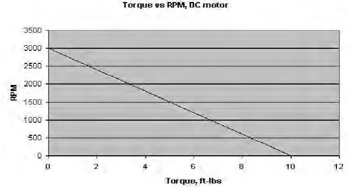
2.1.3 Torque VS RPM
For permanent magnet DC motors, there is a linear relationship between torque and
[image:15.595.145.494.543.729.2]rpm for a given voltage.
6
The maximum torque occurs at 0 rpm, and is called stall torque. The
minimum torque (zero) occurs at maximum rpm, reached when the motor is not
under a load, and is thus called free rpm. The formula for torque at any given rpm is:
T = Ts - (N Ts ÷ Nf)
where T is the torque at the given rpm N, Ts is the stall torque, and Nf is the free
rpm.
Power, being the product of torque and speed, peaks exactly half way
between zero and peak speed, and zero and peak torque. For the above graph, peak
power occurs at 1500 rpm and 5 ft-lbs of torque; 1.4 hp. However, you do not
generally want to run a motor at this speed, as it will draw much too much current
and overheat. The above motor might be rated for only 0.5 hp (1 ft-lbs of torque at
2700 rpm).
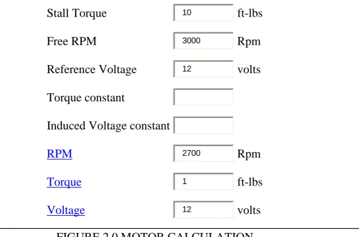
Knowing the stall torque and the free rpm, we can derive two important
constants for the motor in question. First is the induced voltage constant, which
relates the back-voltage, induced in the armature to the speed of the armature.
Ke = V ÷ Nf
Where Ke is the induced voltage constant, Nf is the free rpm, and V is the voltage.
The second important constant is the torque constant which relates the torque to the
armature current.
Kt = Ts ÷ V
7
Using these two constants, we can write the motor equation (these are all the
same equation, solved for different variables):
T = Kt × (V - (Ke × N)
V = (T ÷ Kt) + (Ke × N)
N = (V - (T ÷ Kt)) ÷ Ke
Where T is torque, V is voltage, N is rpm, Kt is the torque constant, and Ke is the
induced voltage constant. The units don't matter, as long as they're the same units
you used to calculate the constants.
Stall Torque 10
ft-lbs
Free RPM 3000
Rpm
Reference Voltage 12
volts
Torque constant
Induced Voltage constant
[image:17.595.165.522.305.540.2]2700 Rpm 1 ft-lbs 12 volts
FIGURE 2.0 MOTOR CALCULATION
Note that these formulas only apply to shunt motors and permanent magnet motors.
8
2.1.4 Torque and Current
Torque is proportional to the product of armature current and the resultant flux
density per pole.
T = K × f × Ia
Where T is torque, K is some constant, f is the flux density, and Ia is the armature
current.
In series wound motors, flux density approximates the square root of current, so
torque becomes approximately proportional to the 1.5 power of torque.
T = K × Ia1.5±
Where T is torque, K is some constant, and Ia is the armature current.
2.1.5 Speed, Voltage, and Induced Voltage
Resistance of the armature windings has only a minor effect on armature
current. Current is mostly determined by the voltage induced in the windings by their
movement through the field. This induced voltage, also called "back-emf" is opposite
in polarity to the applied voltage, and serves to decrease the effective value of that
9
An increase in voltage will result in an increase in armature current,
producing an increase in torque, and acceleration. As speed increases, induced
voltage will increase, causing current and torque to decrease, until torque again
equals the load or induced voltage equals the applied voltage.
A decrease in voltage will result in a decrease of armature current, and a
decrease in torque, causing the motor to slow down. Induced voltage may
momentarily be higher than the applied voltage, causing the motor to act as a
generator. This is the essence of regenerative breaking.
Induced voltage is proportional to speed and field strength.
Eb = K × N × f
where Eb is induced voltage, K is some constant particular to that motor, N is the
speed of the motor, and f is the field strength.
This can be solved for speed to get the "Speed Equation" for a motor:
N = K × Eb ÷ f
Where N is rpm, K is some constant (the inverse of the K above), Eb is the induced
voltage of the motor, and f is the flux density.
Note that speed is inversely proportional to field strength. That is to say, as field
10
2.1.6 Runaway
In a shunt-wound motor, decreasing the strength of the field decreases the
induced voltage, increasing the effective voltage applied to the armature windings.
This increases armature current, resulting in greater torque and acceleration.
Shunt-wound motors run away when the field fails because the spinning armature field
induces enough current in the field coils to keep the field "live".
In a series-wound motor, the field current is always equal to the armature
current. Under no load, the torque produced by the motor results in acceleration. As
speed increases, induced voltage would normally increase until at some speed it
equaled the applied voltage, resulting in no effective voltage, no armature current,
and no further acceleration; in this case, however, increasing speed decreases field
current and strength, stabilizing induced voltage. Torque never drops to zero, so the
motor continues to accelerate until it self-destructs.
Runaway does not occur in permanent magnet motors. Starter motors, electric
car motors, and some golf cart motors are series wound, however, and can run away.
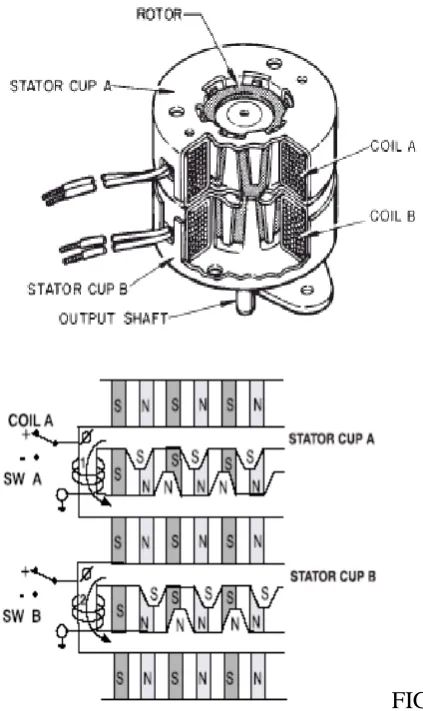
2.1.7 STEPPER MOTOR
Stepper Motors convert electrical pulses into discrete mechanical rotational
movement or steps. Typical stepper motors consists of two coils with two stator cups
formed around each coil. Pole pairs are mechanically displaced by one-half each pole
pair. When current is applied, the pole pairs become alternatively energized north
and south poles. Between the stator coil pairs, there is a displacement of one quarter
11
Stepper motor operating performance specifications may be as follows:
Holding torque, step angle (Degrees), steps/rev, DC operating voltage,
resistance/windings (ohms) for a given applied voltage. Length, diameter, shaft size,
and interface are other mechanical specifications available from the manufacturer.
Typical stepper motors are used in any application which requires a discrete
rotational movement. Examples; an indexing table or conveyor, optical scanner (3D
laser scanner), photo or film processing machine, BBQ grill (we don't want that
chicken to burn), etc. Stepper motors are also used with accompanying mechanisms
(gears) to translate the rotational movement into linear displacement applications.
[image:21.595.120.332.301.657.2]FIGURE 3.0 MOTOR DIMENSION
12
2.1.8 Full Step Stepper Motor
This animation demonstrates the principle for a stepper motor using full step
commutation. The rotor of a permanent magnet stepper motor consists of permanent
magnets and the stator has two pairs of windings. Just as the rotor aligns with one of
the stator poles, the second phase is energized. The two phases alternate on and off
and also reverse polarity. There are four steps. One phase lags the other phase by one
step. This is equivalent to one forth of an electrical cycle or 90°.
This stepper motor is very simplified. The rotor of a real stepper motor
usually has many poles. The animation has only ten poles; however a real stepper
motor might have a hundred. These are formed using a single magnet mounted inline
with the rotor axis and two pole pieces with many teeth. The teeth are staggered to
produce many poles. The stator poles of a real stepper motor also have many teeth.
The teeth are arranged so that the two phases are still 90° out of phase.
This stepper motor uses permanent magnets. Some stepper motors do not
have magnets and instead use the basic principles of a switched reluctance motor.
The stator is similar but the rotor is composed of an iron laminates.
13
2.1.9 Half Step Stepper Motor
This animation shows the stepping pattern for a half-step stepper motor. The
commutation sequence for a half-step stepper motor has eight steps instead of four.
The main difference is that the second phase is turned on before the first phase is
turned off. Thus, sometimes both phases are energized at the same time. During the
half-steps the rotor is held in between the two full-step positions.
A half-step motor has twice the resolution of a full step motor. It is very popular for
this reason.
FIGURE 5.2 HALF STEP
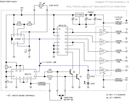
[image:23.595.119.526.458.715.2]2.1.10 Stepper Motor Driver Circuit
14
FIGURE 5.4 STEPPER MOTOR DRIVER TEST CIRCUIT
[image:24.595.121.535.421.744.2]