Dynamically Extending Planning Models using an Ontology
Michael Cashmore, Maria Fox, Derek Long,
Daniele Magazzeni
, and
Bram Ridder
King’s College London
London WC2R 2LS
[email protected]
Valerio De Carolis, David Lane,
and
Francesco Maurelli
Herriot-Watt University
Edinburgh, Scotland, UK EH14 4AS
[email protected]
,
[email protected]
Abstract
In this paper we couple a deterministic planner with an ontology, in order to adapt to new discoveries during plan execution and to reason about the af-fordances that are available to the planner as the set of known objects is updated. This allows us to ex-tend the planning agent’s functionality during exe-cution. We use as an example planning for persis-tent autonomous behaviour in underwater vehicles. Planning in this scenario takes place in a symbolic model of the environment, simulating sequences of possible decisions. Ensuring that the simula-tion remains robust requires careful matching of the model to the real world, including dynamically updating the model from continuous sensing ac-tions. We describe how our system constructs an initial state for planning, using the ontology; how the ontology is also used to determine the results of each action performed by the planner; and fi-nally demonstrate the performance of the system in a simulation, in which two AUVs are required to cooperate in an unknown environment, demon-strating that with additional reasoning the planning system is able to make new efficient choices, taking advantage of the environment in new ways.
1
Introduction and Motivation
AI Planning [Ghallabet al., 2004] supports a key requirement of intelligent robotics: the ability to perform strategic task-level planning, taking into account limited resources, time, environmental constraints and long-term goals. Planners rely on having access to a rich model of the environment, the ob-jects within it, and the actions that can be performed on the different kinds of objects. A major challenge is that knowl-edge of the environment constantly changes during plan ex-ecution, so the set of objects that can be manipulated cannot be fixed in advance. Instead, the planner’s model has to be adapted and updated as new discoveries are made. Acquiring new knowledge in an autonomous way, adapting behaviour accordingly, is a fundamental requirement of persistent au-tonomous behaviour. Path-planning [Lavalle, 2006] is also a fundamental underlying requirement, but we do not address this topic in this paper.
To enable the acquisition and interpretation of data, and inference over the resulting new knowledge, we provide an
ontologyas one of the components of an autonomous plan-based system. This paper addresses using an ontology in the dynamic construction of AI planning models, using under-water mission-planning for AUVs as an example. In the work presented here, the ontology has two roles: to recognise in-stances of known concepts from sensed data (eg: to be able to distinguish a valve from a weld), and to identify affordances with the newly recognised objects (eg: to recognise that, be-ing a valve, the object can be grasped, turned, etc). In this way, interpretation of sensed data opens up new reasoning choices for the planner.
Our goal is to show that, equipped with task planning and an ontology, an autonomous system can perform long-term operations without human intervention, adapting to discover-ies and increasing its functionality over time. Our approach is to plan operations over a horizon, and replan whenever the ontology updates the planning model. We make two main contributions:
1. The use of a temporal planner, rather than a reactive strategy, to control underwater missions, in order to an-ticipate and avoid problems rather than simply react to them when they cause actions to fail.
2. The use of an ontology to provide object classifications and affordances to the planner, to improve the planner’s interaction with the world.
When planning in robotic domains the actions available to the planner correspond to interactions between the robot and recognised objects in the environment, an idea explored by Geib et al. [2006] as Object-Action complexes. If a plan-based intelligent robot is placed in an environment with a fixed model, the robot might not be able to exploit all of its capabilities as objects are not correctly recognised, or are of unknown types that nevertheless afford known interactions. Using ontological reasoning in conjunction with planning, we extend the capabilities of the planner to more closely match those of the robot in the environment.
dis-covery, and be able to model actions that can be performed in the environment in the symbolic language of the planner. The missions that must be undertaken have many temporal con-straints and characteristics. For example, depending on how long it takes to achieve a planned task, the timeframe in which other tasks might be completed can be affected. Thus, de-pending on the importance of tasks, the planner might decide to make more time available for one task rather than another. In cooperative tasks, the planner has to time the behaviours of the cooperating robots so that they coincide at the right locations.
The combination of planning with other modules that model knowledge about the domain has been explored in other contexts. Several approaches to building semantic maps have been developed. Petrick et al. [2013; 2014] address the issue of joining continuous low-level sensor data with plan-ning in a partially-known symbolic representation with sens-ing actions in contsens-ingent plannsens-ing. This is similar to the problem that we propose to tackle with an ontology mod-ule. Where Petrick et al. cope with unknown knowledge at a Planning level, our focus is on using an ontology to reason about discovered objects, and by so doing extend the possi-ble means of interacting with them. Tenorth et al. [2010] and Galindo et al. [2008] focus on combining semantic knowl-edge with spatial data to form asemantic mapof the environ-ment. Tenorth et al. in particular deal with attaching semantic information to a spatial map using an ontology in the ROS1
framework for indoor household tasks. We define a similar, but general approach to linking an ontology with a planner in ROS.
We validate this approach in an under-water mission, which we describe in Section 2, along with discussion related work. In Section 3 we describe the details of our integration between planning and ontology. We describe the simulations with our system and then conclude in Sections 4 and 5.
2
Planning with Ontologies
Ontologies organise knowledge around concept hierarchies and the relationshipsand attributes between these concepts and instances of them. Considerable work has been car-ried out on developing representational languages based on description logics and inferences over the sentences they record [Gruber, 1993]. In our framework, an ontology is used as a way for the robot to organise the knowledge about the physical world in which the AUVs operate, not just as geo-metric concepts, but also as richer structures that offer access to affordances expressed as action templates available in a PDDL [Fox and Long, 2003] domain model (actions applica-ble to objects of the corresponding types).
In this work we use an ontology to detect new objects and reason about their identification and the relations between them. The planner adapts to unexpected features by revising its abstract, deterministic model of the world and replanning to take account of the new features, while relying on robust control and signal processing systems to handle inaccuracy and noise.
1
Robot Operating System (ROS); http://www.ros.org; last ac-cessed Apr. 2014
Combining task planning and control have been considered in much prior work. Recent works include: the constraint-based temporal planning system, EUROPA-2, in the T-REX framework [McGannet al., 2008; Pyet al., 2010]; combin-ing task and motion planncombin-ing onboard the PR2 robot [Srivas-tavaet al., 2014]; using homotopy classes to guide path plan-ning [Hern´andezet al., 2011b; 2011a]; generating a coarse plan to initialise the inspection of an unknown hull [Englot and Hover, 2010]; using a plan-based policy to guide an AUV for autonomously tracking the boundary of the sur-face of a partially submerged harmful algal bloom [Foxet al., 2012] and autonomous underwater maintanence, explored in the context of temporal planning [Cashmoreet al., 2013; 2014];.
2.1
Case Study
We consider a context in which two AUVs have to cooperate to accomplish tasks in a long term mission that requires sus-tained autonomy: the inspection and maintenance of a seabed facility. Some tasks cannot be achieved by a single AUV and coordination between two or more AUVs is required. Our problem scenarios in this paper are set in this context, fo-cussing on a cluster of inspection tasks. Maintenance tasks take place in a dynamic environment; currents will move the robots, visibility might become obscured, and extrane-ous events, such as sea animals passing by, might interfere with the execution of an action. In order to find plans that are robust to the uncertainty inherent in the environment, we con-struct domain models that are conservative with respect to re-source requirements (e.g. time and energy). The uncertainty is abstracted by embedding it in the resource estimates used in planning the actions. In this way, we can exploit powerful deterministic temporal planning methods, rather than proba-bilistic methods which, although they model and reason about uncertainty directly, are much less performant.
exploring a set of inspection points, by navigating close by and directing the sonar and imaging equipment towards them. However, if there are pillars in the structure, the AUVs are able to inspect each complete pillar as a single structure, by observing from a greater distance. This action explores a larger area than any single inspection point, but poses some challenges, as the pillars are deep down in the water, so that a light has to be shone upon the target for the observation to be of sufficient quality.
One solution would be to equip a single AUV with both a camera and a light, but in such a case the light would come from the same direction as the camera, and backscatter would compromise the image quality. Instead, one AUV should ap-proach the pillar and shine the light from an oblique angle, while the other AUV approaches the target to make the ob-servation. Note that it is not possible to sequentialise the be-haviour of the two AUVs for the pillar inspection task. The concurrency of the behaviours is crucial to the success of the inspection. This task therefore requires temporal coordina-tion of activities, and temporal reasoning is key for the effec-tive planning of this mission. The combination of temporal coordination of two AUVs, the assignment of tasks between them and the timing and ordering of tasks is the role of a task plan and cannot be resolved by path planning, although path planning is necessary in determing which navigation tasks are achievable and by what route.
The AUVs are placed inside an environment with a number of pillars and other structures. Initially the AUVs have little knowledge of the environment. The AUVs and planning sys-tem are capable of performing an inspection in an unknown environment by observing dynamically generated inspection points and replanning as new observations invalidate the cur-rent plan.
3
Integration
The symbolic model of the world is provided by the ontology though a ROS interface that the planner uses to construct the initial state of the problem. The symbolic representation of the locations that the AUVs can visit, the objects, and the re-lationships between them are provided by the ontology. This process is described in four parts. First we describe our model for the structure inspection task, and how it is dynamically updated. We discuss how the model recorded in the ontology is delivered as a problem description for the planner. We then show some solutions to examples of these generated planning problems, and finally describe how these plans are executed.
3.1
Model
[image:3.612.337.531.54.201.2]The objects collated in the ontology are either known a pri-ori or are derived from analysing sensor data that is col-lected throughout the execution of a plan. The types of ob-jects include 3d-points within the volume bounding the mis-sion region, which has several subtypes (waypoints, inspec-tion points and strategic waypoints), and structures, which includes the subtypes of pillars and one representing the im-age slice a sonar captures when intersecting a cylinder, which we call aCircle(though it might be elliptical, depending on angle, and will be partially occluded by the solid structure).
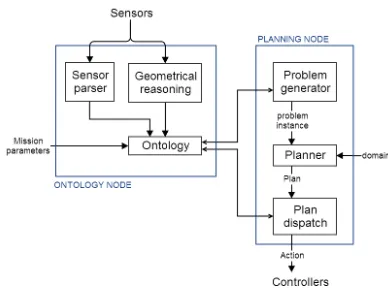
Figure 1: The architecture of integration between the plan-ning system and ontology. The ontology provides the initial state of the planning problem. The ontology is also involved in the exectution of the plan, alerting the planning system when an important part of the environment changes, or is dis-covered to be different from what is expected.
Figure 1 displays the relationship between the planning sys-tem and the ontology.
The possible trajectories the AUVs can traverse are deter-mined by a set ofwaypoints. These waypoints are created using a probabilistic road map (PRM) [Kavrakiet al., 1996; Lavalle, 2006], and stored in the ontology. We use an oc-tomap [Wurm et al., 2010] to check if a waypoint collides with an obstacle in the world. Similarly we use the octomap to determine whether the AUVs can traverse between two waypoints. The octomap is built from sensor data and con-tinuously updated.
Inspection points are added to the ontology. These are ar-eas that must be observed by the AUV, either arar-eas of unex-plored space, or the unseen sides of possible pillars.
The PRM is augmented with additional waypoints – called
strategic waypoints– these waypoints are stored in the ontol-ogy to provide a denser collection of waypoints around points of interest (in our case the locations of possible pillars and unexplored space). For example, if the sonar picks up a sig-nature that is roughly cylindrical, this is recognised as a new
Circleand stored in the ontology. New inspection points are inferred as a consequence of the knowledge that such struc-tures can be inspected on all sides. This has the effect of enabling and encouraging the planning system to plan to in-spect the opposite side of this object to determine whether it is aPillar.
This information can also be used to ’clean up’ the oc-tomap by removing noise. If an object is determined to be a pillar, its shape is known and errors from the sonar can be corrected.
3.2
Constructing the Planning Problem Instance
In our domain, the state of each AUV is partially described by its position, given by a waypoint. The AUV can per-form six actions, namelydo hover fast,do hover controlled,
(:durative-action do_hover_fast
:parameters (?v - vehicle ?from ?to - waypoint) :duration ( = ?duration (* (distance ?from ?to)
(invtime ?v)))
:condition (and (at start (at ?v ?from)) (at start (connected ?from ?to))) :effect (and (at start (not (at ?v ?from)))
(at end (near ?v ?to))))
(:durative-action illuminate_pillar
:parameters (?v - vehicle ?wp - waypoint ?p - pillar) :duration ( >= ?duration 0)
:condition (and (over all (at ?v ?wp))
(at start (can_observe_pillar ?v ?wp ?p))) :effect (and
(at start (pillar_illuminated ?p))
(at start (not (can_observe_pillar ?v ?wp ?p))) (at end (not (pillar_illuminated ?p)))
(at end (can_observe_pillar ?v ?wp ?p)) (at end (near ?v ?wp))))
(:durative-action observe_pillar
:parameters (?v - vehicle ?wp - waypoint ?p - pillar) :duration ( = ?duration 10)
:condition (and
(at start (at ?v ?wp))
(at start (can_observe_pillar ?v ?wp ?p))) (over all (pillar_illuminated ?p))
:effect (and
(at start (not (can_observe_pillar ?v ?wp ?p))) (at end (observed_pillar ?p))
(at start (not (at ?v ?wp))) (at end (near ?v ?wp))))
Figure 2: A fragment of the PDDL inspection-task domain.
The do hover fast action moves the AUV between two connected waypoints (which, by construction, are the end-nodes of a collision-free edge). Since the fast motion does not take into account final orientation, it only arrivesnear
the desired pose. The position must then be corrected. The duration of the action depends on the distance between the two waypoints.
The observe actions allow the AUV to observe an inspec-tion point or a pillar. The precondiinspec-tion requires the AUV to be at a waypoint from which the target inspection point is (partially) visible. Furthermore, theobserve pillaraction re-quires the pillar to be illuminated over the whole duration of the observe action. Theilluminate pillar action, whose du-ration is decided by the planner, needs to be performed by a different AUV to meet this requirement.
The problem instance is described using a collection of ob-jects, their initial states, and a goal. The objects correspond to object types known by the ontology, and the initial state of the problem instance is generated from the attributes of these objects, also stored in the ontology. This describes the current known state of the world. In the structure inspection task the goal is automatically generated from the initial state, given the current knowledge of the environment. This is done by adding the requirement that every inspection point and pillar has been fully observed. This data is accessed using a ROS interface. In a typical scenario, the goal is initially to observe a set of inspection pointsp1, . . . , pn. When a pillar is
dis-covered, the goal is dynamically updated, and some inspec-tion pointspj, . . . , pkare removed from the goal and replaced
with the goal of observing the pillar (as it subsumes multiple
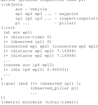
(define (problem inspection-task-p1) (:objects
auv - vehicle
wp1 wp2 wp3 ... - waypoint ip1 ip2 ip3 ... - inspectionpoint)
p1 ... - pillar)
(:init (at auv wp1)
(= (mission-time) 0) (= (observed ip1) 0)
(connected wp1 wp2) (connected wp2 wp1) (= (distance wp1 wp2) 7.16958)
(= (distance wp2 wp1) 7.16958) ...
(cansee auv ip4 wp12) (= (obs ip4 wp12) 0.445331) ...
)
(:goal (and (>= (observed ip1) 1) (observed_pillar p1) ...
))
[image:4.612.318.486.57.237.2](:metric minimize (total-time)))
Figure 3: A fragment of the PDDL inspection-task problem instance.
inspection points,pj, . . . , pk, as determined by the appropri-ate geomtric reasoning in the ontology). Figure 3 shows a fragment of a problem instance.
3.3
Solving the Planning Problem
To solve the problem, we use the temporal planner
POPF[Coleset al., 2010]. As described earlier, the planner deals with coarse-grained events: in this case movement be-tween waypoints and observation of inspection points. Ex-ample plans inPDDLrepresentation are shown in Figures 4 and 5. In both plans, the AUVs are explicitly given concur-rent activities and the planner minimises the duration of the plans. However, in the second case, the planrequires con-currency to allow the correct illumination of the pillar during the (long range) inspection task. Note that the illumination duration has been set by the planner to meet the demands of the inspection task.
3.4
Execution
The controllers are responsible for achieving the actions and providing feedback. There are two possible reasons for re-planning:
1. action failure: an action execution reports failure, using the ROS action feedback, or times out; and
2. change of environment: the ontology notifies the plan-ner of a change in the environment that invalidates the plan, or new information, such as new object instances, pertinent to mission goals.
A single plan governs both AUVs. We make the assump-tion that when replanning, the vehicles can coordinate and share information as required. In practice, this communica-tion is difficult, and in future work we will consider how the plans execution and replanning requests can be coordinated between independent vehicles.
Without knowledge of Pillars
[image:5.612.53.300.51.265.2]Plan time PDDL action duration 0.000: (correct position auv0 wp auv0) [10.000] 0.000: (correct position auv1 wp auv1) [10.000] 10.001: (do hover fast auv1 wp auv1 s16) [46.469] 10.001: (do hover controlled auv0 wp auv0 s0) [14.274] 24.276: (observe inspection point auv0 s0 i0) [10.000] 34.277: (correct position auv0 s0) [10.000] 44.278: (do hover controlled auv0 s0 s1) [16.971] 56.471: (correct position auv1 s16) [10.000] 61.250: (observe inspection point auv0 s1 i1) [10.000] 66.472: (observe inspection point auv1 s16 i16) [10.000] 71.251: (correct position auv0 s1) [10.000] 76.473: (correct position auv1 s16) [10.000] 81.252: (do hover controlled auv0 s1 s2) [16.971] 86.474: (do hover controlled auv1 s16 s20) [15.000] 98.224: (do hover fast auv0 s2 s10) [66.000] 101.475: (observe inspection point auv1 s20 i20) [10.000] 111.476: (correct position auv1 s20) [10.000] 121.477: (do hover controlled auv1 s20 s17) [22.649] 144.127: (observe inspection point auv1 s17 i17) [10.000]
Figure 4: A PDDL plan for an inspection task, found using
POPF. Each action has an associated duration, and expected dispatch time, which may differ from the actual execution. Each waypoint and inspection point is associated with its co-ordinates, as stored in the ontology. In this plan no pillars have been recognised by the ontology.
With knowledge of Pillars
Plan time PDDL action duration 0.000: (correct position auv0 wp auv0) [10.000] 0.000: (correct position auv1 wp auv1) [10.000] 10.001: (do hover fast auv1 wp auv1 s16) [46.469] 10.001: (do hover controlled auv0 wp auv0 s0) [14.274] 0.000: (correct position auv0 wp auv0) [10.000] 0.000: (correct position auv1 wp auv1) [10.000] 10.001: (do hover controlled auv0 wp auv0 s3) [10.833] 10.001: (do hover fast auv1 wp auv1 s16) [46.469] 20.835: (do hover fast auv0 s3 s20) [84.546] 56.471: (correct position auv1 s16) [10.000] 75.383: (illuminate pillar auv1 s16 pillar2) [50.000] 105.382: (correct position auv0 s20) [10.000] 115.383: (observe pillar auv0 s20 pillar2) [10.000]
Figure 5: A PDDL plan for an inspection task, found using
POPF. Each action has an associated duration, and expected dispatch time, which may differ from the actual execution. Each waypoint and inspection point is associated with its co-ordinates, as stored in the ontology. In this plan, knowledge of pillars exists in the intial state, allowing faster observation of the structure.
actions to the AUV controllers. The actions are dispatched to the two AUVsconcurrentlyas scheduled by the plan.
The AUV controllers provide feedback to the executor. If the action is successful, then at the scheduled time, the next action can be dispatched to that controller. If the action is failed, then replanning is triggered. If an action is taking too long to complete, the action is cancelled by the executor and replanning is triggered.
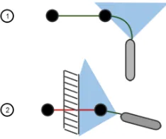
[image:5.612.376.493.56.154.2]During the execution of an action the executor may can-cel the action if the plan is invalidated or the current action
Figure 6: The plan is executed with sonar continuously up-dating the environment. The plan is invalidated in 2 and re-planning is triggered.
is no longer desirable. Note that, in our framework, replan-ningis based onreformulatingthe inspection task as a new planning problem. This re-modelling is performed dynam-ically, as new information becomes available – the PRM is continuously updated according to the new information about the environment, and the ontology with detected objects and structures to inspect. This reformulation allows the AUVs to adapt to new discoveries during execution.
For example, by collating information continuously it is possible that the obstacle is detected long before the action is to be dispatched. The system can alter the plan before the ac-tion is dispatched, thereby avoiding dead-ends and inefficien-cies. For example, consider the following simple scenario in figure 6: the AUV is moving between two waypoints, and the sonar detects a wall. The wall obstructs the planned hover action, but will not interfere with the current action. Clearly, replanning should take place to avoid dispatching the doomed action. In this case the obstructed connection is removed from the ontology, the planning system is notified of the change, and finds a new route before dispatching the action.
4
Experimentation
Our objective is to show that the planner and ontology can interact to support the execution of a complex mission. We have designed experiments that demonstrate the following features:
1. Controlled failure of an executing plan in the event of the discovery of new information
2. The discovery of new object instances and their affor-dances, and updating of the planning problem
3. Replanning of a cooperative mission involving coordi-nated activity of the two AUVs to achieve mission goals
[image:5.612.52.299.353.505.2]# of pillars IPs only IPs and Pillars 1 208.909 117.631 1 216.309 135.814 2 365.618 263.028 2 351.014 350.307 3 758.375 383.531 3 781.005 324.062 Avg time (s) 446.872 262.395 Avg # actions 58 23
Table 1: Plan quality for the structure inspection task. “IPs only” refers to the task undertaken without knowledge of pil-lars. “IPs and Pillars” shows the results when taking knowl-edge of pillars into account.
result in inefficient inspections. We illustrate this by com-paring the behaviour of the AUVs under coordination of the planner with and without the support of the ontology.
The structure inspection missions are carried out in simu-lation, using a system that emulates an underwater environ-ment and interfaces with ROS. The entire control system has been used to plan and execute missions using physical vehi-cles, but we have not had the opportunity to test physical mis-sions with two AUVs together. In the test mismis-sions, the AUVs are sent to inspect different structures with various numbers of pillars. Initial inspection points are placed on the surface of the structure. Our hypothesis is that using the knowledge from the ontology will allow us to generate plans that have a shorter duration, and fewer actions, because the recognition of a specific instance of an object type gives the planner ac-cess to the best affordances to enable efficient interaction with the object. The simulation was run multiple times, first with-out taking into account knowledge of pillars from the ontol-ogy. In this case, all the inspection points had to be observed. Then, the ontological data was taken into account, and pillars could be inspected with the pillar-specific observation action, inspecting multiple inspection points at once.
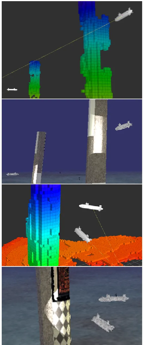
The times taken to execute the missions are reported. The planning time on each planning cycle is limited to 10 sec-onds. Figure 7 shows the simulation during runtime. Using the knowledge provided by the ontology about Pillars greatly reduced the time taken to complete the mission (Table 1). Ex-tending the functionality of the planner with new knowledge about the environment can be expected to increase the quality of the plans based on the improvement of affordances.
5
Conclusion
In this paper we describe the linkage of a planning system to an ontology within an execution framework, allowing the planner to exploit features and affordances of elements of the environment as they are identified and inferred by the ontol-ogy. As the world state is continually modified using pro-cessed sensor data to update the ontology, the executing plan is monitored for validity and replanning is invoked when it ceases to be valid. The result is a system robust to changes in the environment. We tested our system in simulation, show-ing that usshow-ing the ontology to associate objects with affor-dances can result in plans with a shorter duration and fewer actions.
[image:6.612.312.561.54.652.2]References
[Cashmoreet al., 2013] Michael Cashmore, Maria Fox, Tom Lark-worthy, Derek Long, and Daniele Magazzeni. Planning inspec-tion tasks for auvs. InProc. of the MTS/IEEE Oceans 2013 Con-ference, San Diego (OCEANS’13), 2013.
[Cashmoreet al., 2014] Michael Cashmore, Maria Fox, Tom Lark-worthy, Derek Long, and Daniele Magazzeni. Auv mission con-trol via temporal planning. InIEEE Int. Conf. on Robotics and Automation (ICRA’14), 2014.
[Coleset al., 2010] Amanda Coles, Andrew Coles, Maria Fox, and Derek Long. Forward-chaining partial-order planning. InProc. of the 20rd Int. Conf. on Automated Planning and Scheduling (ICAPS’10), pages 42–49, 2010.
[Englot and Hover, 2010] B. Englot and F. Hover. Inspection plan-ning for sensor coverage of 3D marine structures. InIEEE/RSJ Int. Conf. on Intelligent Robots and Systems, 2010.
[Fox and Long, 2003] Maria Fox and Derek Long. PDDL2.1: An extension to pddl for expressing temporal planning domains.
Journal of Artificial Intelligence Res. (JAIR), 20:61–124, 2003. [Foxet al., 2012] Maria Fox, Derek Long, and Daniele Magazzeni.
Plan-based policy-learning for autonomous feature tracking. In
Proc. of the 22nd Int. Conf. on Automated Planning and Schedul-ing (ICAPS), 2012.
[Galindoet al., 2008] Cipriano Galindo, Juan-Antonio Fernandez-Madrigal, Javier Gonz´alez, and Alessandro Saffiotti. Robot task planning using semantic maps. Robotics and Autonomous Sys-tems, 56(11):955–966, 2008.
[Geibet al., 2006] Christopher Geib, Kira Mour˜ao, Ron Petrick, Nico Pugeault, Mark Steedman, Norbert Krueger, and Florentin W¨org¨otter. Object action complexes as an interface for planning and robot control. InProc. of the Humanoids-06 Workshop: To-wards Cognitive Humanoid Robots, 2006.
[Ghallabet al., 2004] M. Ghallab, D. Nau, and P. Traverso. Auto-mated Planning: Theory and Practice. Morgan Kaufmann, 2004. [Gruber, 1993] T. R. Gruber. A translation approach to portable
ontologies. Knowledge Acquisition, 5(1):199–220, 1993. [Hern´andezet al., 2011a] Emili Hern´andez, Marc Carreras, Javier
Antich, Pere Ridao, and Alberto Ortiz. A topologically guided path planner for an auv using homotopy classes. InIEEE Int. Conf. on Robotics and Automation (ICRA’11), pages 2337–2343, 2011.
[Hern´andezet al., 2011b] Emili Hern´andez, Marc Carreras, and Pere Ridao. A Path Planning Algorithm for an AUV Guided with Homotopy Classes. InProc. 21st Int. Conf. on Automated Plan-ning and Scheduling (ICAPS’11), 2011.
[Kavrakiet al., 1996] L. E. Kavraki, J.-C. Latombe P. Svestka, and M. H. Overmars. Probabilistic roadmaps for path planning in high-dimensional configuration spaces. InIEEE Transactions on Robotics and Automation, page 566580, 1996.
[Lavalle, 2006] S. M. Lavalle. Planning Algorithms. Cambridge University Press, 2006.
[McGannet al., 2008] Conor McGann, Frederic Py, Kanna Rajan, Hans Thomas, Richard Henthorn, and Robert S. McEwen. A deliberative architecture for auv control. InIEEE Int. Conf. on Robotics and Automation (ICRA’08), pages 1049–1054, 2008. [Petrick and Foster, 2013] Ronald P. A. Petrick and Mary Ellen
Foster. Planning for social interaction in a robot bartender do-main. InProc. of the 23rd Int. Conf. on Automated Planning and Scheduling (ICAPS’13), pages 389–397, 2013.
[Petrick and Gaschler, 2014] Ronald P. A. Petrick and Andre Gaschler. Extending knowledge-level contingent planning for robot task planning. InProc. of the ICAPS 2014 Workshop on Planning and Robotics (PlanRob), pages 157–165, 2014. [Pyet al., 2010] Frederic Py, Kanna Rajan, and Conor McGann. A
systematic agent framework for situated autonomous systems. In
Int. Conf. on Autonomous Agents and Multiagent Systems (AA-MAS’10), pages 583–590, 2010.
[Srivastavaet al., 2014] Siddharth Srivastava, Eugene Fang, Lorenzo Riano, Rohan Chitnis, Stuart Russell, and Pieter Abbeel. Combined task and motion planning through an extensi-ble planner-independent interface layer. InProc. IEEE Int. Conf. on Robotics and Automation (ICRA’14), 2014.
[Tenorthet al., 2010] Moritz Tenorth, Lars Kunze, Dominik Jain, and Michael Beetz. KNOWROB-MAP - knowledge-linked se-mantic object maps. InHumanoids, pages 430–435, 2010. [Wurmet al., 2010] Kai M Wurm, Armin Hornung, Maren