2007
Painter training in virtual reality: conceptualization,
design, and implementation
Steven Lee Pautz Iowa State University
Follow this and additional works at:https://lib.dr.iastate.edu/rtd Part of theComputer Sciences Commons
This Thesis is brought to you for free and open access by the Iowa State University Capstones, Theses and Dissertations at Iowa State University Digital Repository. It has been accepted for inclusion in Retrospective Theses and Dissertations by an authorized administrator of Iowa State University Digital Repository. For more information, please [email protected].
Recommended Citation
Pautz, Steven Lee, "Painter training in virtual reality: conceptualization, design, and implementation" (2007).Retrospective Theses and Dissertations. 15427.
by
Steven Lee Pautz
A thesis submitted to the graduate faculty
in partial fulfillment of the requirements for the degree of
MASTER OF SCIENCE
Major: Human Computer Interaction
Program of Study Committee: Dirk Reiners, Major Professor
Derrick Parkhurst Carolina Cruz-Neira
Iowa State University
Ames, Iowa
2007
1460086
2009
Copyright 2007 by Pautz, Steven Lee
TABLE OF CONTENTS
LIST OF FIGURES ... iv
ABSTRACT ... v
CHAPTER 1. OVERVIEW ... 1
1.1 The Problem...2
1.1.1 The painting activity ...3
1.1.2 Current training practices ...8
1.2 The Solution... 10
1.2.1 Virtual reality training feasibility ... 11
1.2.2 System overview ... 12
1.2.3 Usage scenario... 12
1.2.4 Audience and context ... 15
1.3 Related Work ... 16
1.3.1 Early work on surface painting ... 16
1.3.2 SprayPaint, by the Johnson Center for Virtual Reality ... 18
1.3.3 VirtualPaint, by Star4D... 19
1.3.4 Electronics and Telecommunication Research Institute work ... 19
1.3.5 Conclusion ... 24
CHAPTER 2. CONCEPT AND RATIONALIZATION ... 25
2.1 Overview ... 25
2.1.1 Operating costs ... 26
2.1.2 Incident costs ... 27
2.1.3 Cost summary ... 28
2.1.4 Virtualization... 29
2.2 Activity and Task Design ... 29
2.3 System Requirements ... 30
2.3.1 Physical spray gun ... 30
2.3.2 Real-time spray and feedback ... 31
2.3.3 Paint attribute visibility ... 31
2.3.4 Training guidance ... 31
CHAPTER 3. TECHNICAL OVERVIEW ... 33
3.1 Physical Equipment ... 33
3.1.1 Baby Cave virtual reality system... 33
3.1.2 Paint spray gun ... 37
3.2 Software Libraries and Frameworks ... 39
3.2.1 VR Juggler ... 39
3.2.2 Additional frameworks ... 40
3.2.3 Languages and libraries ... 41
3.3 Internal Components ... 41
3.3.1 Simulation component ... 41
3.3.2 PaintManager component ... 43
3.3.3 DrawingCanvas component ... 43
3.3.4 InputData component ... 45
3.3.5 PaintSprayer component ... 47
3.4 General Painting Algorithm... 52
3.4.1 PreFrame data collection ... 52
3.4.2 Data processing and event handling ... 52
3.4.3 Core simulation: paint spraying ... 53
3.4.4 Core simulation: surface simulation ... 54
3.4.5 Core simulation: display ... 54
3.5 Other Algorithms and Operations ... 55
3.5.1 Painting onto the canvas ... 55
3.5.2 Running the surface simulation ... 57
3.5.3 Displaying the paint data ... 59
CHAPTER 4. SURFACE SIMULATION DETAILS... 63
4.1 Overview ... 64
4.1.1 Surface modeling ... 64
4.1.2 Paint data ... 65
4.1.3 Surface operations ... 66
4.2 Paint Surface Behavior ... 67
4.2.1 Cohesiveness ... 67
4.2.2 Flow ... 68
4.2.3 Drying ... 68
4.3 Surface Behavior Implementation ... 69
4.3.1 Surface shader parameters ... 69
4.3.2 Algorithm for surface behavior ... 70
4.4 Paint Display ... 75
4.4.1 Available shaders ... 75
4.4.2 Layering ... 76
4.4.3 Atomization and reflections ... 77
4.5 Display Implementation ... 78
4.5.1 Display shader parameters ... 78
4.5.2 Algorithm for paint display ... 79
CHAPTER 5. SUMMARY AND DISCUSSION ... 84
5.1 Excluded Simulation Features ... 84
5.1.1 Three-dimensional parts ... 85
5.1.2 Head tracking ... 87
5.1.3 Stereo vision ... 88
5.2 Possible Training Features ... 89
5.2.1 Training scripts ... 89
5.2.2 Profiles and scoring ... 90
5.3 Anecdotal Results ... 91
5.3.1 Public demonstrations ... 92
5.3.2 Expert reviews ... 93
5.4 Conclusion ... 94
BIBLIOGRAPHY ... 96
LIST OF FIGURES
Figure 1. Usage scenario... 15
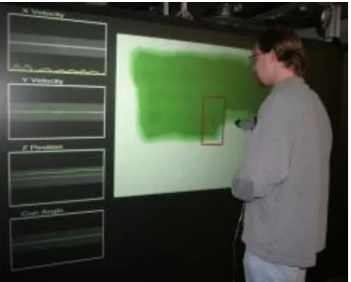
Figure 2. Using the simulation with extra feedback enabled ... 32
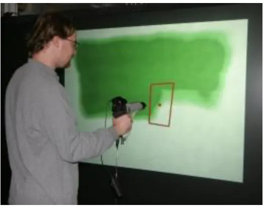
Figure 3. Using the simulation without extra feedback ... 32
Figure 4. Spray gun with tracker attached ... 38
Figure 5. Paint on projection screen ... 95
Figure 6. Feedback on projection screen ... 95
Figure 7. Screenshot of paint ... 95
ABSTRACT
This thesis describes the conceptualization, design, and implementation of a tool
which simulates the activity of spray painting, intended to augment the training of industrial
spray painters at John Deere. Spray painting is a difficult task, and current methods of
training do not result in the desired level of trainee expertise and performance. Through close
cooperation with stakeholders at John Deere, a virtual reality-based simulation tool has been
created, which provides a realistic recreation of the spray painting experience--particularly
the feedback offered by the behavior and visual appearance of paint sprayed onto a surface.
This paper discusses the motivation, intent, structure, and technical details which define and
direct that simulation.
A number of technologies were used in this simulation, and a number of algorithms
developed, in order to provide an accurate and effective reproduction of the spray painting
experience. These include the use of a physical paint spray gun, the software modeling of
various system components and their interactions with each other, the creation of several
different tools and features for feedback and review, and the detailed simulation of both the
behavior and the visual appearance of wet paint applied to a surface, in accordance with the
specific attributes of the paint. These features provide feedback similar to—and in some
cases greater than—the feedback available during the actual paint spraying process, allowing
a trainee to develop the skills necessary to ensure proper paint application without incurring
CHAPTER 1. OVERVIEW
With the growing power and ubiquity of computing technologies, there is tremendous
potential for frequent, important, or difficult activities to be improved in ways never before
imagined. For such potential benefits to be realized, however, computing technologies must
be applied in an appropriate manner: their purpose, behavior, and interface must respect the
presence and actuality of many non-technological factors. Primary among these factors are
the needs and goals of people and the safety, appropriateness, and effectiveness of the
activities performed by those people in the pursuit and fulfillment of their needs and goals.
This is particularly true in educational and training settings, where an inappropriate or
ill-conceived employment of technology could not only result in a failure to learn important
material, but might also lead to the learning of inappropriate or incorrect material. Once a
particular manner of doing things has been committed to memory and mastered, it is very
difficult to ―re-teach‖ a different way of doing things, so there is a critical need to provide a
successful learning experience from the start. This requires careful and precise
conceptualization, design, and implementation of the technologies used to augment the
learning experience such that they are driven by the users and stakeholders, and by the
activities pursued by those users and stakeholders.
One educational area which has not yet realized the full benefits of technology is the
training of industrial paint sprayers. Current methods of training are hampered by a number
of physical and practical limitations, and as a result the proficiency of newly-trained spray
painters is oftentimes inadequate (Meyers & Keller, personal communication). This project
employed by trainers to increase the effectiveness of their instruction. This simulation
removes nearly all of the physical and practical limitations inherent to the ‗real‘ painting
activity, while retaining the benefits of the activity, so that the fundamental skills and
behaviors related to effective paint spraying may be mastered during training.
1.1 The Problem
Industrial spray painting is not an easy job. A painter must apply a consistent coat of
paint with the proper thickness across the entire part being painted, or else the desired effects
of the paint—aesthetic appeal, rust protection, etc—will be greatly diminished or absent,
rendering the part useless. In order to create a high-quality coat of paint, a number of
considerations must be followed: the paint spray gun must be kept at the proper distance
from the part being sprayed, held at an appropriate angle and orientation, moved at a suitable
speed, and adjusted to the necessary settings for the desired fluid flow. Arguably the most
important skill, though, is the ability to recognize whether or not these considerations have
been met—the painter must be able to consistently and accurately ascertain the success or
failure of their painting job based on the appearance of the part. Extensive experience is
necessary in order to develop an intuitive feel for most of these skills and considerations
1.1.1 The painting activity
The task of applying a high-quality coat of paint to a metal part is complex and
difficult. The physical painting environment imposes a number of safety and protocol
requirements, the operation of the paint spray gun requires specific skills and behaviors, and
the nature of the paint itself demands care and attention. Taken as a whole, the spray painting
activity requires significant declarative and procedural knowledge in addition to precise
physical movements.
1.1.1.1 Physical setup
In order to perform the painting activity, an operator must first prepare the
environment: the industrial paint booth. There are different paint booths for different types
and sizes of part, spanning everything from individual sheets of metal up to large,
fully-assembled vehicles, but all paint booths provide the same general function: to create an
environment which is safe and conducive to effective painting. The archetypical paint booth
at John Deere is a large, open room where unpainted parts enter on one end, are painted by
the operator, and then leave out the other end. The floor of the booth is adjustable, so that the
operator may move it up or down to more easily access the part from different heights or
perspectives. The ceiling is ventilated, such that air flows upwards from the floor, carrying
solvent fumes and stray paint particles out of the area. The booth is very well-lit and is kept
free of unnecessary objects and obstacles.
The paint booth holds a number of possible health and safety threats, so the operator
must wear a special suit and take special precautions while in the booth. These include a
garment, a special set of ―overalls‖, protects the operator‘s body from solvent fumes, paint
particles, and any other harmful chemicals which might occupy the paint booth. It does not
limit the operator‘s movement in any significant or meaningful way. To protect the
operator‘s feet, both from paint chemicals and from the possibility of hitting an obstacle,
operators wear heavy, steel-toed rubber boots. To protect the head, operators wear a
multi-layer headpiece made of the same material as the protective garment. This headpiece restricts
the field of view considerably: the operator can only look straight ahead, through a
glare-proof plastic window which allows an approximately 45-degree field of view. Although the
total range of neck movement is not significantly restricted, the headpiece does make neck
movements slower and more difficult.
Due to the pervasiveness of evaporated solvent and other airborne chemicals, an
external air source is required. A tube carries air from a fresh source into the booth, where it
attaches to the back of the operator‘s headpiece, providing a steady stream of fresh air as well
as some much-needed cooling. Additionally, because of the noise generated by the booth‘s
ventilation system and by the production facility as a whole, operators must wear ear
protection at all times.
The final category of physical equipment and considerations is the painting system
itself: the liquid paint and the spray gun by which it is applied to a metal part. The spray gun
is connected to two tubes: one provides liquid paint, the other air, both under pressure. The
two are combined together—according to controls and parameters set by the operator—to
create a fine mist which is propelled away from the gun. At the beginning of a work session,
match the slight day-to-day variations in paint mixture and ambient temperature as well as
his or her personal preferences and work style.
1.1.1.2 How paint works
In a very general sense, paint is composed of two categories of compounds: solvents
and insolubles. Insolubles provide the desirable effects of the coat of paint: color, rust
protection, etc, while solvents are volatile liquids which act as a vehicle for transporting the
insolubles into the part. Both are applied in (ideally) roughly equal portions to the surface of
the part, and over time the solvent dissipates, leaving the insolubles bonded to the part.
When liquid paint is combined with pressurized air by the spray gun, thousands of
tiny droplets are formed—a thin mist which is propelled away from the gun. When these
paint droplets come into contact with a surface they adhere to it, partially out of friction and
partially due to an electrostatic charge. As more droplets accumulate on a surface and begin
to cover it, they join with one other and form a cohesive surface of paint—depending on the
specific paint mixture, this tends to happen at approximately 1 mil of thickness, or one
one-thousandth of an inch. Once this surface has dried (i.e., when the solvent has evaporated) this
will become a solid, aesthetically-pleasing sheet of protective paint.
That is the ideal scenario; however, a number of issues or occurrences can result in
inferior results. Paint solvent begins to evaporate as soon as the paint leaves the spray gun, so
if the droplets do not reach a surface quickly enough then the mixture of solvent and
insolubles will become imbalanced and dry. This would result in no surface cohesion: the
already-dry droplets would never combine together into a solid surface, leading to a rough
surface: with inadequate paint to form a cohesive surface, individual droplets would dry by
themselves, also leading to a rough and ineffective coat of paint.
The opposite problem of too much paint would also cause problems. A good,
cohesive coat of paint is relatively unaffected by gravity (or, more accurately, is bonded to
the surface by forces stronger than gravity) but as more and more paint is added there will
eventually reach a point where the weight of the liquid paint is greater than the forces
adhering it to the surface—depending on the specific paint mixture, this tends to happen at
approximately 3-6 mil of thickness. Once this happens the excess paint will begin to move
downwards, forming ―sags‖, areas where the paint has pooled up on the surface of the part,
resulting in a noticeable ridge on the surface of the part. If there is enough excess paint on the
part, the paint will overflow that ridge, forming ―drips‖, large drops of paint which roll down
the surface of the part. Although sags and drips do not imply a failed coat of paint—unlike an
incomplete and incohesive coat of paint, they still offer rust protection—they are considered
very unaesthetic and a waste of paint (which has both economic and environmental costs).
Although minor sags might be allowable on a part which is out of sight, the
overwhelming majority of parts with inappropriate coats of paint (i.e., coats with sags, drips,
or a lack of cohesion) must be sanded down, reconditioned, and repainted at a later date. This
is a very expensive, labor-intensive, and time-consuming process, and so the occurrence of
1.1.1.3 Operator and spray gun movements
Although inappropriate coats of paint may be the result of external factors such as
ambient temperature, erroneous paint mixtures, or external distractions, the overwhelming
majority of mistakes are the result of inappropriate application of the paint by an operator—
particularly if the operator is new or inexperienced. The single most effective and most
reliable way to ensure good, consistent coats of paint is to have a skilled operator.
Due to differences in body size and personal preference, each operator uses a slightly
different technique for painting. Regardless of their specific movements, though, most
operators move the spray gun in a regular, predictable way. The gun is kept at a specific
distance from the part, moved with a consistent speed and orientation, and used to apply a
specific rate of paint to the part per second.
The distance between the paint spray gun and the part being painted is one of the key
factors in painting. If the gun is too close then too much paint will be applied to too small an
area, resulting in sags and/or drips; while if it is too far away then the paint droplets will dry
before the reach the canvas, resulting in a thin or incohesive coat of paint. Although the exact
optimal distance varies slightly depending on operator preference and other factors such as
speed of movement, the ideal distance set by John Deere is 12-15 inches from the part.
Similarly, the spray gun must be kept perpendicular to the surface being painted—otherwise
one section of the area being sprayed will receive more paint than the other areas.
In order to ensure a smooth, even coat the spray gun must be moved smoothly and
constantly. This is relatively each to achieve in the middle of a spray path, but somewhat
more difficult at the beginning and end of a movement. If the movement begins or ends with
compensate for this, operators begin painting ―off‖ the part, then move to spray gun at a
constant speed over the part itself, and then end ―off‖ the part.
This is the foundation of the standard movements used by operators: painting the
surface in a series of ―stripes‖. Each ―stripe‖ involves moving the spray gun in front of the
surface in a straight line, at a consistent distance and speed, such that a single band of paint is
applied. Due to the manner in which the paint mist is sprayed from the gun, this stripe will be
lighter at the edges than in the middle, so the stripes are overlapped—the operator centers
each stripe on the bottom of the previous stripe, resulting in 50% overlap and a much more
even coat of paint.
The final result is that the gun is moved back and forth across the surface at a
constant distance, perpendicular to the surface, in a series of straight-line movements which
overlap with each other. These movements can be left/right or up/down, and the beginning
and end of each movement—the point where the spray gun slows down and reverses
direction—takes place off of the part (i.e., to the left, right, top, or bottom of the part) so that
excess paint will not build up at those points. This pattern of movement encompasses nearly
all of the sub-skills and considerations used by painters on any part.
1.1.2 Current training practices
Current training practices at John Deere do not provide adequate experience and
expertise for these skills and considerations, however. Due to time, monetary, and resource
costs, new trainees cannot receive training in the paint booth itself. Instead, trainees are
currently trained in the classroom, where they receive excellent coverage of the declarative
how one should go about creating a good coat of paint, and why it is important. They do not
receive any hands-on training or experience at all, however, prior to being moved to the
assembly line, and as a result there is a strong tendency for new trainees to create many
poor-quality coats of paint which must be redone at great expense.
1.1.2.1 No booth-based training
It is not feasible to train new trainees in a real paint booth, due to a number of safety
considerations and restrictions. The safety gear (protective suit, earplugs, etc) which must be
worn significantly reduces the operator‘s visual field and hearing, severely inhibiting or
outright preventing communication between the trainer, trainee, and any observers.
Electronic communication (e.g., radios) is not allowable for safety reasons: due to the high
flammability of solvent fumes, no electric devices are permitted in the paint booth.
Although painters could theoretically be trained in a real booth, the costs—in both
time and materials—are simply too great to make such an approach practicable. Even if these
challenges were somehow overcome, though, there are no spare paint booths in which to hold
training. All booths are used for production at all times, and the cost of designing,
constructing, and running a new booth would far surpass any potential savings.
1.1.2.2 Other infeasible approaches
A number of additional solutions to the training problem have been suggested, but to
date none has been satisfactory enough to pursue. Chief among these has been robotic
painting; simply replacing the human painters with robot arms. Although this would be an
Deere tend to be complex enough that the difficulty and cost of programming the robotic
arms does not justify their potential benefit. Additionally, the specific parts being painted are
always changing, with new parts being introduced regularly. Human painters can adapt
readily to these new parts, as nearly all can be painted effectively using the skills and
techniques mentioned earlier, but robotic arms would need to be re-programmed for every
single new part.
Another suggestion has been to change the properties of the painting task—or, more
specifically, change the type or properties of the paint so that sags and drips do not form.
Although there are paints in existence which are far more resilient against mistakes, these
paints do not yield the characteristics and benefits which John Deere desires, particularly in
terms of long-term protection, drying time, and visual aesthetics.
1.2 The Solution
Classroom-based training, by itself, is inadequate, while on-the-job training is
expensive and time-consuming. The idea of improving the training of spray painters is
well-grounded, however: previous research has shown that proper and effective training of
industrial spray painters can lead to significant reductions in material waste and
environmental contaminants while concomitantly and significantly increasing overall
production (Joseph, R., 1998). If there was some way to remove the costs of the on-the-job
training, while simultaneously allowing it to be integrated into classroom-based training, the
result would likely deliver a significantly greater degree of post-training expertise than is
This project involves the conceptualization, design, and implementation of such a
system. Using technologies from the fields of virtual reality (VR) and computer graphics, the
spray painting experience has been recreated in a way which removes nearly all of the costs
of on-the-job training while retaining nearly all of its benefits, in a way which can be
integrated into a classroom curriculum or other educational setting with minimal imposition.
1.2.1 Virtual reality training feasibility
The idea of using virtual reality to train workers on complex tasks is well-founded. In
addition to several similar projects which have used VR to successfully augment painter
training (see below), VR and related technologies have been used as a training tool for a wide
variety of jobs and activities, including laparoscopic surgery (Gallagher, et.al., 1999; Jordan,
et.al., 2001; Seymour, et.al, 2002) and industrial welding (Fast, Gifford, & Yancey, 2004;
Wormell, D. & Foxlin, E., 2003).
Many of these projects have demonstrated, with data, that virtual reality-based
training can be as effective as training using physical reality—i.e., that virtual reality can lead
to a high transfer of training, particularly if the virtual environment is immersive (Psotka,
1995; Rose, et.al., 1998; Rose, et.al., 2000)—but with reduced cost and, in some cases, less
time investment. Thus, there is reason to expect that a realistic, immersive, and
appropriately-designed virtual reality-based training system would be an effective and
inexpensive method for training industrial spray painters. The current system, intended to
1.2.2 System overview
There are three key components to this system: a spray gun for applying paint, a
projection screen for displaying the part being painted, and the software simulation which
connects the two. The system works almost identically to a physical paint booth, without the
costs and limitations innate to such booths, and with the addition of software features to
assist both the trainer and the trainee—such as real-time feedback and review modes on the
quality of the application of the paint and the quality of the resulting coat. The design and
construction of such a system involves a number of technical challenges, which are discussed
in later chapters.
The general operation of the system involves a user standing in front of the projection
screen and using a sensor-fitted paint spray gun to interact with the display. The most
common form of interaction is painting: the user points the spray gun at a part to be painted,
presses the trigger, and virtual paint flows onto the part. The location and speed of the virtual
paint‘s application correspond to the movement of the gun, such that appropriate use of the
spray gun leads to a satisfactory coat of paint while inappropriate use of the spray gun leads
to a poor coat of paint. The spray gun is also used to interact with the user interface of the
simulation, navigating menus and changing settings similar to the way a mouse is used to
point and click on a desktop user interface.
1.2.3 Usage scenario
Because this structure and form of this simulation so closely replicates the actual
spray painting activity, an activity-centered description of the project is given rather than
specific equipment used and algorithms employed are found in chapters 3 and 4. The
simulation‘s use proceeds as follows:
Upon starting the application, a blank metallic ―canvas‖ is projected in front of the
trainee. This is the part to be painted: a single large, flat part reminiscent of ―class A‖ parts
painted by John Deere operators (e.g., high-visibility parts like vehicle hoods or doors).
These parts tend to generate a large number of errors, partially due to their size and partially
due to the extra-strict quality requirements necessary for high-visibility parts. Additionally,
they are ideal for learning and practicing the standard back-and-forth movement employed by
painters—the movements which encompass nearly all of the key critical skills necessary for
painting any part.
By default, pointing the paint spray gun at the display will reveal a small outline
which delineates the region which will receive paint when the gun‘s trigger is pressed. This
outline follows the movements of the gun in real-time, much like a typical on-screen pointer
follows the movements of a mouse. It is useful both as a general feedback tool, to show
exactly where the paint spray will go, and as a visual guide for lining up the paint spray with
existing areas of paint on the screen, as is necessary when performing the ―50% overlap‖
stripes used to ensure an even coat of paint.
When the spray gun is pointed at the screen and its trigger pressed, virtual paint
appears on the part, covering the region targeted by the spray gun. When the paint is first
applied to the surface it appears thin and rough, with flecks and small droplets of paint only
partially obscuring the metal underneath. As more paint is added, however, the metal
becomes fully concealed behind a cohesive, smooth, shiny coat. This specific change—the
as the key characteristic to look for when trying to create a good coat of paint. If paint
continues to be added past this point, it will eventually begin to run down the canvas,
forming into visible sags and drips—flaws which require significant cost to clean up and fix.
As the virtual paint sits on the virtual canvas it slowly dries, losing some shininess and
leaving behind a solid coat.
Once the painter has finished painting the part, he or she (or the instructor) can pull
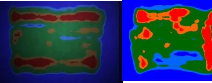
up an on-screen menu and switch to a ―feedback mode,‖ which changes the appearance of the
paint from ―realistic‖ (i.e., replicating the actual visual appearance of the paint) to a
multi-colored display which encodes different ranges of paint thickness as different colors. Areas
with too much or too little paint jump out immediately, allowing more direct and specific
feedback than is offered by the ―realistic‖ view.
The painter can switch back and forth between the different views of the paint as
desired, possibly receiving feedback and advice from a trainer while doing so. When the
painter wishes to repeat the painting process, he or she (or the instructor) can simply clear the
Figure 1. Usage scenario
1.2.4 Audience and context
It is assumed that all trainees will have undergone some education on the general
workings and handling of the spray gun prior to using the simulation, similar to what is
currently received in the classroom—although observations of public demonstrations of this
simulation suggest that no prior knowledge or training is necessary to understand or use this
system. It is also assumed that a professional instructor will be nearby to assist with
interpretation of results and guidance for better performance—although, anecdotally, several
testers and new users during public demos were able to improve their performance noticeably
after only a few minutes of use, with only minimal instruction and guidance about the
interpretation of the feedback.
Although all trainees are expected to have the general knowledge necessary to
understand what the system is and how to respond to its feedback, the simulation itself (as
and information that success with the system does not depend on, and is not restricted by,
knowledge about the system or about the painting activity as a whole.
1.3 Related Work
Although there is not yet a large, established body of literature on the topic of
VR-based painter training, several other projects, both previous and ongoing, deal with similar
concepts and goals as this project—such as the activity and experience of spray painting, the
goal of augmenting painter training and/or performance, the application of paint onto a
surface, or the technical implementations by which the above may take place. However, no
project exactly targets the specific goals and end results sought by this project, none uses the
specific technical implementation employed here, and none uses this project‘s conceptual
approach to feedback (i.e., replicating surface behavior and visual feedback of the paint
surface). Similar or related projected are discussed below.
1.3.1 Early work on surface painting
Although it does not specifically deal with spray painting or painter training, there has
been considerable work on the process of applying surface data (in a general sense) to a
three-dimensional (3D) surface in the more general field of computer graphics. Graphical
surface attributes like color/material, texture coordinates, and other surface characteristics
must be applied in a correct manner to desired or appropriate locations. The high level
concept is very similar to spray painting: the user wishes to create a particular effect on a
In both 3D painting and spray painting, there are particular techniques and user
interactions which must be performed to achieve the desired results. In spray painting, these
involve the movements of the painter and the paint spray gun; in 3D painting they involve the
use of specialized user interfaces for specifying and applying various attributes in an
unambiguous manner. For example, a user may define surface attributes such as color,
reflectivity, or texture, orient to a particular portion or view of a 3D surface, and then apply
those attributes using a type of brush (Hanrahan & Haeberli, 1990; Daily & Kiss, 1995)—in
effect, creating a 2D window into the 3D world and then performing actions which affect the
targeted portion of the 3D world. These projects and contributions also confirm the high
degree of overlap between 2D painting operations and techniques and their 3D counterparts,
in terms of user operation (and thus training)—a strong justification for the use of a 2D
canvas, as discussed above.
It should be noted that, within the context of 3D painting, direct paint application
could be achieved through the use of a physical part and a space-tracked stylus or paintbrush
(e.g., Agrawala, Beers, & Levoy, 1995). This requires a physical part and physical scanner,
however, and places many restrictions on the activity (e.g., significant set-up time, inability
or great difficulty in moving the physical part, and physical separation between input and
display; Agrawala, Beers, & Levoy, 1995). Keefe, et.al. (2001) removed the reliance upon a
physical part by moving the application into a Cave Automated Virtual Environment (CAVE;
Cruz-Neira, Sandin, & DeFanti, 1993) and allowing the user to ‗paint‘ anywhere within the
3D space. Due to being an artistic tool rather than a training tool, however, the system
supported neither a discrete part or canvas nor a specific goal for the operator—two elements
For this project, an interface to manipulate or orient a 3D world is unnecessary, as the
present system uses 2D parts. Additionally, there is no need to apply a variety of independent
surface characteristics, as in spray painting the paint itself carries all relevant characteristics.
The general concept of applying elements to a surface in order to achieve a desired result—
and the explored avenues by which this may be achieved—support the concept and value
proposition of this project, although the specific features and functionality present in the
literature do not meet the specific needs of this project. Although 3D surface painting
applications have great use for 3D model design and construction, they neither provide the
inputs nor the outputs necessary to replicate the spray painting activity and user experience.
1.3.2 SprayPaint, by the Johnson Center for Virtual Reality
A publication on painter training by Heckman, J. & Joseph, R. (2003), describes a
system designed and built by the Johnson Center for Virtual Reality in Minnesota which is
conceptually similar to the one described here, although differences in implementation
between the two systems lead to significantly different features and emphases. Few technical
details are given, so a detailed comparison of the two projects is not possible, but several key
differences in technologies used suggest different approaches despite the similar concepts.
As described in chapter 4, this project employs a surface simulation of paint—
specifically cohesiveness and the formation of sags and drips—as one of the primary forms
of feedback. To our knowledge no other project utilizes either behavioral feedback or surface
simulations. There are likely several other differences between the projects, but the use of a
surface simulation is likely to be the most profound difference between our paint spraying
1.3.3 VirtualPaint, by Star4D
Another system, VirtualPaint (2006), designed and built by the Iowa Waste
Reduction Center at the University of Northern Iowa, also bears many similarities to this
project. As with the SprayPaint project, technical details are very sparse, but the system
appears to be very similar to the Johnson Center‘s SprayPaint project, from a conceptual and
functional standpoint: modeling of the application and thickness of paint, but no modeling of
surface behavior or surface visual characteristics.
One addition of the VirtualPaint project is the inclusion of an optional ―LaserPaint‖
targeting tool: a physical attachment for spray guns which relies on the focusing of two laser
beams to provide feedback about spray gun position and orientation (2006). Although the
system developed here does not include this specific addition, functionally-equivalent
feedback is provided to the trainee through software.
1.3.4 Electronics and Telecommunication Research Institute work
Some recent work by the Electronics and Telecommunication Research Institute
(ETRI), in association with the Information and Communications University, Korea, is
pursuing the goal of painter training, yet using very different means than have been utilized
here (Kim, et.al, 2007; Yang, et.al, 2007). Although the context of training deals with
ship-building, the motivation for an improved method of training—and the restrictions which
make the use of real paint infeasible—mirror this project very closely. Fundamental
differences in the assessment of user needs and in the determination of forms and methods
for feedback led to the creation of a system which differs significantly from the system
As is detailed later (see section 5.1), the use of several standard, conventional virtual
reality features—such as 3D geometry, stereo vision, and head-tracking—were rejected from
this project after it was ascertained that they would yield minimal benefit or contribution to
the painter training process, yet incur substantial cost in implementation time and detriment
to trainer-observer interaction. Instead, it was decided to emphasize visual characteristics of
the paint coat—specifically its on-surface behavior (cohesiveness, flow, drying, etc) and
visual properties (atomization, reflections, texture, etc)—as they represent the visual
feedback elements which paint sprayers are trained to recognize and respond to. The ETRI
system does not incorporate these features.
1.3.4.1 System similarities
Despite their independence and differences in priority, there are a number of
similarities between these two projects. Both incorporate a physical spray paint gun for input;
both use raycasting to determine the area targeted by the paint spray; both allow operator
adjustment of factors which affect the paint flow and its properties; both track and provide
feedback on the thickness of the paint coat.
Most of these features are based on either the actions taken by the operator during the
spray painting activity (e.g., physical spray gun use, manipulation of spray gun controls) or
on standard algorithms (e.g., raycasting to determine target frustums). Similarly, although
technical details are not available, it is likely that the aforementioned systems—SprayPaint
1.3.4.2 System differences
The differences in functional scope between these projects—3D geometry, stereo
vision, head tracking, surface behavior modeling, and surface appearance modeling—lead to
a number of system-level differences between these two system. The implications of these
decisions are discussed here. Justifications for specific system design decisions is provided
elsewhere in this thesis, particularly chapters 2 and 5.
The decision of whether or not to use 3D geometry has a number of far-reaching
implications—not the least of which being that it requires stereo vision and head tracking,
two additional decisions with far-reaching implications. The use of a single 2D part for this
project greatly simplified all operations involving that part, particularly the application of
paint and the simulation of paint surface behavior and visual properties. These
simplifications allowed for much greater detail and quality to be achieved within each
operation. The precision and depth of computation used for these operations could not have
been achieved in real time if the system had employed 3D geometry rather than a 2D surface.
Although the use of 3D geometry would likely bring some benefit, it was determined that the
expertise and skill desired of new painters at John Deere—specifically, the familiarity with
and understanding of general techniques which apply to many different parts—could be
taught as effectively using 2D.
The use of technologies which create a viewer-specific rendering of the part—such as
head-tracking and stereo vision—can interfere with the communication and interaction
between the trainer, trainee, and any additional observers. At John Deere, this personal
interaction is one of the key elements of training; it allows a trainer to assess the strengths
that others may learn as well. The incorporation of head tracking and stereo vision—both of
which are made effectively mandatory by the use of 3D parts—would restrict the system
such that only the primary user or any observers located in close proximity could view the
display easily. Although special modes could be introduced to overcome this for specific
contexts (e.g., post-painting review in a classroom), merely introducing perspective-related
technologies removes most of the potential for real-time communication between trainer,
trainee, and any observers, and so it was determined that any benefits provided by such
technologies would be outweighed by the cost of this loss of communication.
Finally, due to technical reasons (discussed in chapter 4), the desire to incorporate
real-time surface simulations for the paint‘s on-part behavior and appearance effectively
requires the part to have a flat, 2D surface. A 3D surface could potentially be simulated using
a variety of 2D surfaces, but for the calculations performed by these surface simulations such
a translation would be extremely difficult to perform at all—much less in real-time—using
current video card hardware and technology. Much as the use of a 3D canvas would require
the use of head-tracking, the desire to incorporate surface simulations required this
simulation to a use 2D canvas. The potential benefits of these simulations—both in their
close association with the forms of feedback which painters are trained to recognize and
respond to, and in their ability to improve immersiveness (which, as mentioned above, can
improve both transfer of training and overall training time)—led to the decision that the
benefits of incorporating surface simulations for paint behavior and visual appearance
1.3.4.3 Additional comparisons
In addition to the large, foundational differences discussed above, there are several
minor differences between the systems as well. The ETRI system provides haptic feedback
through the use of compressed air—a feature which was discussed but not implemented in
this project, due to cost-benefit uncertainty. The system presented here uses a detailed,
custom-made fan pattern (the distribution of paint which is emitted from the spray gun),
based on samples taken from a physical spray gun, while the ETRI system uses a simple
Gaussian distribution. The ETRI system is somewhat more flexible in its displays—it can be
used with either CAVE-style back-projected displays or with a head-mounted display—
although the present system‘s use of VR Juggler allows for a great degree of flexibility as
well. Finally, the ETRI system‘s future plans may include elements such as wind and
olfactory feedback—two items which have not been considered for this system, and which
are unlikely to be incorporated in the near future.
Although the system developed by the ETRI and the present system both seek to
address the same general problem and goal, the means by which the two systems pursue that
end differ greatly. While the system developed by the ETRI may be appropriate for the spray
painting activity as performed by the ship-building industry, it does not provide the features
which were judged to be most important for the spray painting activity as performed by
industrial spray painters at John Deere. Concurrently, it provides features which may not
support the training or activity as performed at John Deere. As such, the presence of that
1.3.5 Conclusion
Although several existing projects bring significant benefits to the process of painter
training, none have employed either on-surface paint behavior or atomization and light
reflection to provide feedback to the painter—both of which are central features of this
simulation. Information from project stakeholders at John Deere and anecdotal experiences
with a physical paint booth both emphasized the importance of these forms of feedback, and
so it is believed that their inclusion provides both an increased degree of realism and an
increased level of feedback to the painter, both of which should result in greater efficiency
CHAPTER 2. CONCEPT AND RATIONALIZATION
To increase new painters‘ competency and skill with the paint spraying process as a
whole, competency and skill must be developed in the topics and aspects of painting upon
which the paint spraying process relies. These topics and aspects can be categorized as the
physical actions performed (e.g., the physical movement of the paint spray gun and the
painter‘s body), the results achieved by those actions (e.g., the relationship between those
physical movements and the quality of the resultant coat of paint), and the overall goal or
purpose which those results seek to achieve (e.g., the desired characteristics and attributes of
the final painted part). A training tool must provide activities which develop competence and
skill within each of these areas in order to build competence and skill for the paint spraying
process as a whole.
2.1 Overview
Fortunately, there already exists an activity which develops knowledge and skill in all
three of these areas: the paint spraying activity itself, as performed on-the-job by experienced
spray painters. This activity yields all of the desired benefits, yet it is not used for painter
training because it also carries enormous costs, in both time and money. The underlying
challenge, then, is not to rethink the entire paint spraying activity in search of another activity
with more benefits, but rather to rethink the aspects and elements of the activity which lead
to the prohibitively-high costs. It is these costs—and not an absence of effectiveness—which
strategy for this spray painter training tool, then, is to minimize the costs of spray painting
without affecting the user experience of spray painting.
2.1.1 Operating costs
The costs associated with the spray painting activity, as performed in a physical
booth, can be categorized broadly as time costs and material costs. Time costs include
personnel time, booth time, preparation time, and feedback time. Personnel time refers to
man-hours spent by painters—the costs of paying a skilled employee to perform the job.
Booth time refers to the use of the paint booth for a particular purpose: the booth cannot be
used for more than one activity or more than one part at any particular time; any time spend
on one part or one activity (e.g., on-the-job training) is time which cannot be spent on other,
potentially more profitable uses. Preparation time refers to the time required to clean, season,
and otherwise prepare a part to be painted. An ill-prepared part will have imperfections
which affect the paint‘s ability to adhere to the part, or which negatively impact the aesthetic
or rust-protecting qualities of the paint. Feedback time refers to the duration of time spent
waiting for the paint to dry so that the results of the paint spraying can be determined—the
time between spraying the wet paint and observing the outcome as a final coat. This time
significantly extends the feedback loop for painters, such that errors or mistakes may be
difficult to detect—and thus difficult to avoid repeating.
Material costs include the monetary cost of paint, part, and equipment, as well as
environmental costs. Paint, part, and equipment costs are relatively straightforward—they
refer to the amount of money spent on raw materials. Paint is a complicated compound, and
complicated and expensive, and require additional time and chemicals in order to properly
prepare them for painting. Safety equipment, such as paint suits, masks, and breathing tubes,
also presents costs, both to obtain the equipment and to properly clean or dispose of it once
painting has finished. Environmental costs are similarly varied, as they include not only the
direct impact of paint and other chemicals on the environment, but also the indirect costs of
transporting materials, maintenance and inspection, and clean-up of any leaks or spills.
2.1.2 Incident costs
In addition to operating costs incurred through normal usage of the physical paint
spray booth, additional costs are incurred whenever a mistake or error occurs, either due to
operator error or due to the spray painting equipment or environment. The most common
such error is a poor coat of paint: a coat which does not offer adequate rust and scratch
protection, is not aesthetically pleasing, or otherwise fails to meet John Deere‘s desired
quality standard.
In the event of poor coat of paint, the part is removed from the assembly line, cleaned
and stripped of all paint, and returned to the assembly line later. This process is extremely
expensive, as it involves considerable time and a number of steps: the part must be repeatedly
sanded down and its paint thinned away, left to dry and cure for a period of time, then
re-prepared and finally re-inserted into the assembly line. This process must be done regardless
of the manner in which the coat of paint is inadequate (too thick, too thin, etc) or the reason
Incidents involving equipment—both routine and unexpected—can also contribute to
the costs of painting in a physical paint booth. Hoses and spray guns must be cleaned
regularly, and various spray gun parts may need to be replaced. Additionally, larger pieces of
equipment may fail unexpectedly. Although these incident costs are not directly related to
training, they represent the risks and potential pitfalls associated with use of a physical paint
booth, and are thus potential areas which a training system might improve upon.
2.1.3 Cost summary
In considering this list of costs, a general trend arises: nearly all of the costs result
from the physical aspects of either the paint booth or the paint itself—there is very little cost
incurred by the actions performed by the painter. It is not the painter‘s arm movements which
determine the cost of a flawed coat of paint, but rather the nature of the paint and the part
being painted. Booth time, preparation time, feedback time, and essentially all material and
incident costs could all be considered the result of physical limitations and restrictions, rather
than an intrinsic requirement of the operator‘s actions.
This provides a very promising line for potential improvements to be offered by a
training system: If the physical limitations and restrictions which currently increase the costs
of the paint spraying activity could be removed without removing the beneficial elements of
the activity, then a training system could be created which allows those beneficial elements
2.1.4 Virtualization
The same technologies which support other virtual reality applications can be used to
duplicate the paint spraying activity and experience in a manner which does exactly this:
retaining nearly all of the activity‘s benefits while avoiding nearly all of its costs. This is the
basis for this project.
Replicating a real-world activity in VR is easier said than done, however: it‘s
infeasible to include everything, so the key elements of the experience must be identified so
that they may be prioritized accordingly. Critical elements of the experience must be
continuously refined and polished so that they match their real-world counterparts, while
irrelevant elements must be identified so that no more time than absolutely necessary will be
spent designing and/or developing them.
2.2 Activity and Task Design
To discern between necessary and irrelevant elements of the paint spraying activity,
the tasks which compose the activity must be examined. These tasks can be considered
within the scope of the three elements of the painting process identified earlier: the physical
movements of the paint spray gun and the painter‘s body, the effects of such movements on
the resulting coat of paint and its various attributes, and the desired attributes and outcome of
the final painted part. A task or feature which aligns closely with one of these is likely to be
important, while a task which does not support one of these is likely to be superficial or
Deriving and defining tasks from those elements of the paint spraying activity gives a
small list of features which the system would likely need to support well: physical handling
and use of a real spray gun, real-time feedback on the effects of spraying, multiple methods
for ascertaining paint attributes and quality, and information and guidance on the attributes of
a good coat of paint. These general, high-level features provide enough information to
establish broad, rough requirements for the system as a whole.
2.3 System Requirements
The general goal of increasing new painters‘ competency and skill led to the
identification of several fundamental elements of the paint spraying activity (and its
associated competencies and skills), which in turn led to the identification of several
task-oriented features. These features provide a general foundation for the scope of the project,
and for establishing several general system requirements. These requirements are discussed
below; the simulation presented here fulfills all of these.
2.3.1 Physical spray gun
The spray gun is the primary tool of the painter—the painter‘s mastery of it (or lack
thereof) is the single greatest predictor of the quality of the final coat of paint. It is simply not
possible to master the painting process without mastering the spray gun. Thus, the system
must provide a realistic spray gun experience—which requires measuring and processing
aspects of the spray gun which are used by painters, such as gun position, gun orientation,
2.3.2 Real-time spray and feedback
The system must provide feedback on the effects of spraying (such as the
accumulation of paint on the part‘s surface) which matches the feedback seen in the real
world. To achieve this, the processes of adding paint onto the canvas and displaying that
canvas to the painter must both run at real-time speeds. Additionally, one or more real-time
feedback mechanisms are likely to be beneficial, in order to shorten the feedback loop
between spray gun movements and potential spray pattern shapes and sizes.
2.3.3 Paint attribute visibility
In the physical paint spraying process there are several different cues for gauging the
thickness of a coat of paint—most of them visual. The simulation must convey paint
thickness in the same manners as are available with real paint. Additionally, it would likely
be beneficial to include one or more additional methods of conveying thickness which are not
available with real paint. With real paint, thickness is conveyed via color, texture,
cohesiveness, and movement—these represent the minimum level of visible feedback which
should be presented to the trainee.
2.3.4 Training guidance
The simulation must provide ample opportunity for the trainee to receive information
and guidance about the desired outcome, and about how to best achieve that outcome. Given
the known expertise of the trainer, the context and general environment of the simulation
The system must not detract from the instructor‘s words or actions; noisy or distracting
[image:39.612.191.441.171.372.2]environments are thus not conducive to training.
Figure 2. Using the simulation with extra feedback enabled
[image:39.612.190.441.421.585.2]CHAPTER 3. TECHNICAL OVERVIEW
A number of technical challenges must be overcome in order to create a system which
fulfills the aforementioned requirements. Fortunately, due to the versatility of many virtual
reality technologies, many of these technical challenges have already been solved by reusable
frameworks or equipment. This chapter discusses the high-level employment of several such
frameworks and equipment, as well as several additional technical problems and the
project-specific means by which they were addressed.
3.1 Physical Equipment
Due to the nature of this project, the reuse of existing hardware wherever possible
was imperative: there was inadequate time and money—and inadequate justification—to
create new equipment specifically for the paint spraying simulation. Fortunately, a number of
existing pieces of equipment were both readily-available and well-suited for this project. The
various pieces of hardware used in this project can be categorized with either the Baby Cave
(a multi-purpose virtual reality system, see below) or the paint spray gun (the specific input
device for this simulation).
3.1.1 Baby Cave virtual reality system
The core piece of equipment used to drive the paint spraying simulation is the Baby
Cave, a portable and relatively inexpensive virtual reality system which acts as a Cave
Automated Virtual Environment (CAVE; Cruz-Neira, Sandin, & DeFanti, 1993). The design
but it possessed a number of attributes which made it particularly appropriate for this project.
These attributes and their relevance to this project are discussed below.
3.1.1.1 Projected display
The Baby Cave provides three large projection screens, measuring 8′ x 6′ each and
offering passive stereo capabilities. Each screen is driven by two workstations and two
projectors, with the image back-projected onto the screen so that users do not cast a shadow
over the image. A single non-stereo display is sufficient for operating the spray painting
simulation, however—and for technical reasons discussed later, the simulation must run on a
single video card—so only one screen and one workstation and projector are used.
One display screen is more than adequate to replicate the spray painting activity:
there is ample space to display a wide variety of parts for the trainee to practice on, and an
open area through which the painter can move freely. The 8′ x 6′ screen is large enough to
display nearly any part which a trainee may need or want to practice on, but if an even larger
screen were ever needed, the simulation application can operate on a display of virtually any
size (within the limits of video card memory and capabilities).
In addition to allowing for a variety of part sizes, the large projection screen
accommodates the full range of motion through which a painter moves while painting: the
display does not need to scroll or zoom at any point; the entire part is shown at all times.
Because of this, all interaction between the painter and the part to be painted takes place via
physical movements—there are not scrollbars or buttons, just like in the real paint booth.
such user interface widgets and elements helps to ensure both realism and immersiveness
while the user is painting.
The projector behind the screen fulfills several necessary criteria as well. First and
foremost is the use of back-projection: if a standard front-projection setup were used, the
painter would cast a shadow onto the screen, obscuring the part and destroying the realism of
the simulation. Second is the resolution: the pixel spacing is dense enough that the image
does not appear pixilated except in the rare cases where a viewer specifically attempts to
perceive the individual pixels; yet it‘s coarse enough that the simulation can still run in
real-time—if too dense a resolution were used, the amount of computation necessary to simulate a
square centimeter of painted surface would be far too large to calculate in real-time (see
chapter 4 for more details of these calculations). Although these properties and
characteristics were present in the Baby Cave prior to this project, their appropriateness for
the paint spraying simulation—and the reuse of equipment which this appropriateness
allowed—saved significant time and effort for this project.
3.1.1.2 Context and environment
The overall setting and atmosphere in which the simulation is run must support
classroom-style communication and interactions. One of the key benefits of the use of a paint
simulation for training—as opposed to use of a physical paint booth—is the potential for
allowing and encouraging one-on-one communication between the trainer, the trainee, and
any additional observers. For the simulation to reach its full potential as a training tool, then,
communication—and, ideally, the environment ought to encourage and enhance such
communication within a wide array of scenarios.
The Baby Cave is especially well-suited to these communication needs. Its basic
structure—a portable, back-projected screen with a wide viewing angle and no formal
constraints on audience size—allows a large number of trainers, trainees, and observers to
view or comment on the simulation. Furthermore, the presence of the Baby Cave does not
interfere with communication within or between any of those groups, as it makes no
discernable noise and does not erect any barriers between potential communicators.
3.1.1.3 Position and orientation tracker
As the Baby Cave is a virtual reality system, it includes a system for tracking the
position and orientation of a viewer and any wands or other equipment being used by the
viewer. For this project, the wireless head tracker was used to track the position and
orientation of the paint spray gun in real-time. After calibration, this tracker provided the
information necessary for the simulation application to determine, in real-time, the exact
region of the canvas which the gun was being pointed at (if any).
3.1.1.4 Computer workstation
Both the VR tracker and the display‘s projector were connected to a computer
workstation running Linux. This workstation ran the spray painting application and
communicated with the various hardware devices which provided input to, or received output
3.1.2 Paint spray gun
Although the Baby Cave itself provided all of the equipment needed to handle the
various inputs and outputs of a general VR application, the specific needs of the paint
spraying activity required a more specific input device. This was achieved by modifying and
integrating a physical paint spray gun into the existing Baby Cave equipment.
3.1.2.1 Physical gun
The physical spray gun was provided by John Deere: all of the internal components
were removed from one of their factory guns, leaving an empty shell with the same
appearance and mechanics of the real gun, but without the high cost and complexity. The
wireless head tracker from the Baby Cave (discussed above) was attached to the top of this
gun such the tracker continuously reported the position and orientation of the gun—which in
turn allowed the simulation application to determine the exact point on the canvas where the
Figure 4. Spray gun with tracker attached
3.1.2.2 Gun trigger and IBox
Although the spray gun‘s mechanical trigger still functioned properly, a small button
switch had to be added to determine when it was pressed. The button was fitted into the space
behind the trigger, such that pressing the trigger depressed the button to complete a circuit,
while releasing the trigger removed pressure from the button, opening the circuit. This circuit
was connected to an IBox, a physical interface device which processed the electrical signals
from the button‘s circuit and communicated the trigger state back to the computer on which
the simulation was running. With the addition and connection of the trigger switch and the
IBox, all relevant inputs from the gun were processed and delivered in real-time, fulfilling
3.2 Software Libraries and Frameworks
Just as reusable hardware was employed for a significant portion of the physical
equipment, reusable software was employed for several major components of the simulation.
These components and responsibilities are described below.
3.2.1 VR Juggler
VR Juggler, a framework which abstracts both hardware and software components of
a virtual reality application, was used as the foundation of the software. All hardware inputs
and outputs, as well as the various control functions and stages which define the application,
were managed via VR Juggler. The abstraction of hardware was performed via a customized
set of VR Juggler configuration files, while the abstraction of the application itself was
achieved through use of the VR Juggler classes.
A set of VR Juggler configuration files had already been created for the Baby Cave
VR system; these were modified to suit the specific needs of the simulation. Support for the
IBox was added, unnecessary displays were removed (such that only one projector for one
screen remained), and inputs corresponding to the tracking data and trigger state for the gun
were defined within these configuration files.
Within the software itself, the VR Juggler framework was used to encapsulate the
simulation: the VR Juggler framework and kernel handled the high-level of the execution of
the program, passing execution to the simulation when necessary or appropriate. This is a