International Journal of Innovative Technology and Exploring Engineering (IJITEE) ISSN: 2278-3075, Volume-8 Issue-9, July 2019
Over/Under Voltage Tripping Circuit for
Distributed System Load with GSM alert using
Microcontroller
Rajveer Singh, Rajendra Kumar, Rebecca, Hamzah Shabbir, Abdullah Zahid
Abstract: This paper introduces microcontroller based over voltage and undervoltage protection of domestic appliances and monitoring them through GSM. It starts with the importance of using micro controller in controlling voltage condition, it covers up the aspects why this method of protection is better and simpler than conventional method. We used ATmega32 microcontroller and Sim 900A GSM module to get the status of the supply voltage, be it the time of tripping or at any instant by sending specific text to GSM module. We have also added LCD to get voltage value at any time and status during abnormal condition.There is a limit set for a range of voltage that would be considered normal working condition.Microcontroller will check this condition and trip load if it does not satisfy.Under voltage and overvoltage are one of the major issues prevailing at domestic level that can affect electrical appliances. This method of protection can curb this issue significantly.
Keywords: Overvoltage, under voltage, ATmega32, 16x2 LCD, GSM Sim 900A
I. INTRODUCTION
An overvoltage or a swell is an event in which the voltage level root mean square(r.m.s.) value lies in the range of 1.1 p.u. to 1.8 p.u. at the supply frequency and lasts for a time interval ranging between half cycle to one minute. An undervoltage or a sag is an event in which the voltage level root mean square (r.m.s.) value lies in the range of0.1 p.u. to 0.9 p.u. at the supply frequency and lasts for a timeinterval ranging between half cycle to one minute. Sagging of voltage is quite common problem in power system. The sagging of voltage or undervoltage has quite an adverse effect both on commercial as well as industrial consumers such as malfunctioning of various technology based equipments such as PLCs, motors etc. On the other hand, swelling of voltage or overvoltage causes severe problems too such as breakdown of insulation.
Revised Manuscript Received on July 05, 2019.
Rajveer Singh, Assistant Professor, Electrical Engineering Department, Jamia Millia Islamia University, New Delhi, India
(Rajendra Kumar,) Rebecca, Associate Professor, Computer Science Department, Jamia Millia Islamia University, New Delhi, India
Hamzah Shabbir, Abdullah Zahid Student, Electrical Engineering Department, Jamia Millia Islamia University, New Delhi, Indi
The nominal supply voltage of the system does not cause high insulation stress but overvoltage doescause such high insulation stress that are dangerous to the line and the system connected to it and may cause irreparable loss if protective actions are not taken. Modern production equipment increasingly needssome form ofexternal protection to prevent damageor shut-down during supply disturbances [1].
II.
POWER
QUALITYPower quality refers to working voltage and current under specified range and perfection in the shape of waveform in terms of pure sinusoidal and minimum distortion. The term power Quality is defined by two characteristics, first, reliability, i.e. continuity of supply, second, rapid restoration of service. The specifications for good power quality are as follows:
1. Variation of electrical quantity should be within guaranteed tolerance limits.
2. Pure sinusoidal wave with limited distortion. 3. Balanced three phase voltages.
4. Reliable supply.
5. Earthing system should serve its purpose properly. Power Quality problems can be detected by following observations:
1. A part of equipment mis-operates at the same time of the day.
2. Circuit breakers get trippedwithout actually being overloaded.
3. Failure of equipment during bad weather conditions.
4. Automated system stops working for no genuine reason.
III.
OVERVOLTAGE
An overvoltage is an event in which the voltage level root mean square (r.m.s.) value lies in the range of 1.1 p.u. to 1.8 p.u. at the supply frequency and lasts for a time interval ranging between half cycle to one minute [2]. Overvoltagesare mainly of two types as follows:
I. External Overvoltage: These types of overvoltages mainly arises fromatmospheric disturbances generally because of lightening. Such conditions may arise due to any one of the following reasons: -
a) Direct strokes of lightening. b) Side strokes of
c) Voltages induced along the length of the line because of change in atmospheric conditions. d) Electrostatically induced overvoltages because
of availability of the charged clouds nearby. II. Internal Overvoltages: These overvoltages arise
because of change in operating conditions of the network. Internal overvoltages are grouped into two categories as follows:
1. Switching overvoltage: These overvoltages are caused by transient phenomena which appear due to switching of load and they cannot be avoided. These overvoltages are generally oscillatory and take the form of a damped sinusoid.
2. Temporary Overvoltages: These overvoltages are the steady-state voltages of power system frequency may result from the disconnection of load, particularly long transmission lines cases.
IV.
UNDER VOLTAGE
An undervoltage or a sag is an event in which the voltage level root mean square (r.m.s.) value lies in the range of 0.1 p.u. to 0.9 p.u. at the supply frequency and lasts for a time interval ranging between half cycle to one minute [2]. The condition of sagging of voltage generally arises when heavy loads are switched on like when an induction motor is started it draws 6-10 times of full load rated and this lagging current causes a dip in voltage across the impedance of the system.
V.
MICROCONTROLLER
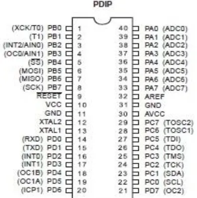
[image:2.595.56.254.535.734.2]AVRAT mega is a family of 8-bit microprocessors from Atmel [3].The Atmel AVR ATmega32 is a low-power CMOS 8-bit microcontroller based on the AVR enhanced RISC architecture [9]. ATmega32 executes powerful instructions in a single clock cycle whichallowing the system to optimize power consumption and processing speed.
Fig 1: Pin diagram of ATmega32 Microcontroller The ATmega32 provides the following features: 32Kbytes of Programmable Flash Program memory with
Read-While-Write capabilities, 1024bytes EEPROM, 2Kbyte SRAM, 32 general purpose I/O lines, 32 general purpose working registers, three flexible Timer/Counters,Internal and External Interrupts, a serial programmable USART,an 8-channel, 10-bit ADC [4].
5.1 USART
The Universal Synchronous and Asynchronous serial Receiver and Transmitter (USART) is an extremely flexible serial communication device. USART has following features:
•Operation:Full Duplex
•Operation:Master or Slave Clocked Synchronous •Baud Rate Generator of High Resolution
•Noise Filtering Detection: False Start Bit and Digital Low Pass Filter
•Communication Modes: Multi-processor Communication and Double Speed Asynchronous mode[4].
5.2 Analog to Digital Conversion
The ATmega32 features a 10-bit successive approximation ADC .These ADC are connected to channels of port A.ADC contains circuits makes sure that input voltage to ADC is kept at constant level during conversion.
VI.
HARDWARE DESIGNING
The circuit shown in fig 2 protects refrigerators or any other electronic appliances from overvoltage and undervoltage.
Table 1: The specifications of the test system
Source 220V, 50 Hz, AC
Transformer 220/12V, 2 Amp
Diode 1N4007
Resistors 10k, 1k
Capacitors 1000 uF, 10uF, 470uF
Voltage Regulator LM7805, 5V
LCD RG1602A, 16X2, Power
supply (5V ± 10%)
Atmega32 microcontroller 4.5-5.5V
Quartz Crystal 8 Mhz
GSM module GSM sim900A, RS 232
interface, 12V
Static Relay Module 5V
The fluctuation is quite frequent in AC mains. To protect the load from such fluctuations and thereby from getting damaged, certain measures are to be taken. This protection circuit providing tripping mechanism is designed in such a way thatit disconnects the load from the supply whenever the input supply voltage exceeds or falls down below the required optimum voltage. The internal logicallows the relay to initiate a tripping sequence whenanomalous conditions arise within the power system[7]. Further, this circuit, with the help of amicrocontroller and a GSM interface sends a message to the owner about the same. Also, this circuit allows the user to know the voltage status on his mobile, at any instant of time, just by sending a message to the GSM number inserted in GSM 900A module.A LCD is connected to show the value of the supply voltage whenever required. A 16x2 LCD means it can
International Journal of Innovative Technology and Exploring Engineering (IJITEE) ISSN: 2278-3075, Volume-8 Issue-9, July 2019
Fig 2: Schematic Diagram
The circuit consists of a transformer to step down the voltage from 220V to 12V. With the help of center tap diode bridge and a potential divider a voltage of 5V is fed to the microcontroller. Any fluctuation in the input to the transformer causes a fluctuation in the voltage fed to the microcontroller. The Atmega32 microcontroller compares this voltage with the reference value and if the voltage exceeds the specified limits, it sends a signal to the relay, the GSM module and the LCD. The LCD displays the input voltage under normal operation whereas it displays the status ‘UnderVoltage’ and ‘OverVoltage’ when the corresponding phenomenon occurs. [10] To power microcontroller, GSM module and the LCD, a power supply is given separately. For this a voltage regulator is provided which gives a constant 5V output. Whenever the voltage becomes more or less than the required voltage, the microcontroller sends a signal to the relay to trip the circuit and disconnect the electrical load from the supply. At the same instanceit sends a signal to the GSM module, which further sends a message to the specified mobile number.
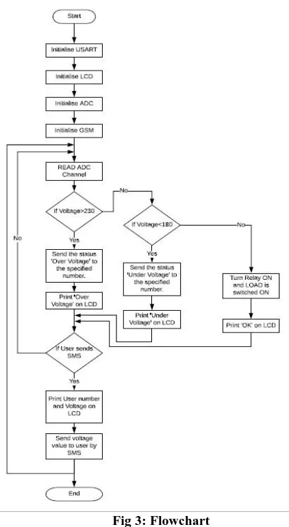
6.1Flowchart
The flowchart to describe the coding done on the microcontroller ATmega32 is shown in fig 3. The steps involved are as follows:
Step 1: Initialize USART. It establishes a connection for reception and transmission to communicate with PC/external modules.
Fig 3: Flowchart
Step 2: Initialize LCD. It interfaces a 16X2 LCD with the microcontroller.
Step 3: Initialize ADC. ADC allows us to interact with the physical world, to read data from sensors using microcontroller.
Step 4: Initialize GSM. It interfaces GSM module with the microcontroller to allow users to send/receive SMS.
Step 5: If the supply Voltage is greater than 230V, then the relay remains disconnected and the status is ‘Over Voltage’. If not, check the next condition.
Step 6: If the supply voltage is less than 180V, then the remains disconnected and the status is ‘Under Voltage’. Step 7: If not, then this means the supply voltage is within range. The Relay is turned ON and the load is connected to the supply.
Step 8: If the user sends a message, then send the voltage value to the specified number by SMS.
VII.
RESULT
The tripping mechanism we designed for protection of electrical devices from under voltage and over voltage isolates or disconnects the load from the supply when the voltage is below 180V or above 230V. Between 180-230V is the normal operation of the electrical load.
1. Under Voltage
[image:3.595.53.265.53.220.2]tripping mechanism. When a supply voltage of 177V is given to the load, the microcontroller sends a signal which trips the relay and disconnects the load from the supply. At the same time, it sends a signal to the GSM module which sends a message to a specified number that an under voltage has occurred. The LCD also shows the undervoltage value and the status as shown in fig. 4.
Fig 4: Result for under voltage
2. Over Voltage
[image:4.595.56.276.143.330.2]Any voltage value above 230V is considered to be over voltage for this tripping mechanism. When a supply voltage of 235V is given to the load, the microcontroller sends a signal which trips the relay and disconnects the load from the supply. At the same time, it sends a signal to the GSM module which sends a message to a specified number that an over voltage has occurred. The LCD also shows the over voltage value and the status as shown in fig. 5.
Fig 5: Result for over voltage
3. Normal Operation
Any voltage value between 180-230V is considered to be normal operating voltage range for this tripping mechanism. When a supply voltage of 218V is given to the load, the microcontroller sends a signal to the LCD which shows the voltage value and the status ‘OK’ as shown in fig. 6.
Fig 6: Result for Normal operation
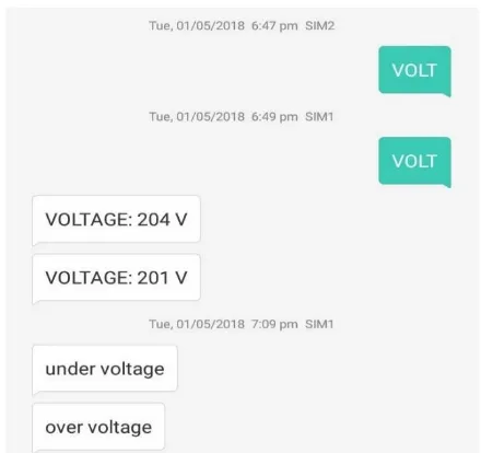
[image:4.595.316.536.316.523.2]This Tripping mechanism for over voltage and under voltage protection of electrical devices includes a special feature. The user could get the status and the supply voltage value at that instance any time. We sent a message ‘VOLT’ and then received a message that showed the value of the supply voltage at that instance. This message is shown in fig 7.
Fig 7: Message sent to receive the value of SupplyVoltage
VIII.
CONCLUSION
In this paper, we have discussed about the problems caused by under voltage and over voltage in industrial applications as well as for consumer goods. We designed a system using a microcontroller and a GSM module to disconnect the load from the supply during the event of overvoltage and under voltage and this system also sends a message about the same to a specified number. Along with this, if the user desires to know the supply voltage at any instance, a message could be sent and the value of the supply voltage is received by the user.
REFERENCES
1. [1] G.A.Taylor, A.B. Burden , “Wide Area Power Quality – Decision Processes and Options for
[image:4.595.56.279.460.656.2]International Journal of Innovative Technology and Exploring Engineering (IJITEE) ISSN: 2278-3075, Volume-8 Issue-9, July 2019
(CIRED’97), pp. 2.30.1-2.30.5, Birmingham, UK, June 1997
2. [2] Manish Paul, Antara Chaudhury, Snigdha Saikia (2015), “Hardware Implementation of Overvoltage and Under Voltage Protection”,Vol. 3, Issue 6,pp. 140-144, Guwahati, India
3. [3] Wojciech Kunikowski, Ernest Czerwiński, Paweł Olejnik, Jan Awrejcewicz (2015), “An Overview of ATmegaAVR Microcontrollers Used in Scientific Research and Industrial Applications”, Lodz University of Technology, 90–924 Łódź, 1/15 Stefanowskistr 4. [4]http://www.atmel.com/products/microcontrollers/avr/ default.aspx 5. [5] “IEEE Recommended Practice for Monitoring Electric Power
Quality,” IEEE Std. 1159-1995, June 1995
6. [6] G. Ramarao, Sateesh K Telagamsetti and V. S. Kale, “Design of Microcontroller based Multi-
7. Functional Relay for Automated Protective
8. System”, pp. 978-1-4799-4939-7, Nagpur, India, 2014
9. [7] I. Zamora, A.J.Mazon, V. Valverde, E. Torres, and A. Dysko “power quality and digital protection relay”,. IEEE Proc., pp. 1-7, 2005.
10. [8] SandroGiannyAquilesPerez, “ Modeling Relays For Power System Protection Studies”. IEEE Proc., pp. 566 – 569, 2005.
11. [9] R.Nicole, “T W. Durfee “ Arduino Microcontroller Guide,” University of Minnesota, 2011.
12. [10] Y. Yorozu, Paithankar, and S.R.Bhide, Fundamentals of Power System Protection. ISBN-81-203-2194-4, 2010.
AUTHOR’S DETAIL
Dr. Rajveer Singh has received B.Tech. Degree (Jamia Millia Islamia, Central University, New Delhi), M. Tech. Degree (NSIT, Delhi University, New Delhi) in the year 2003 and Ph.D. Degree in Electrical Engineering (JMI, New Delhi, India). He is currently working as Assistant Professor in the Department of Electrical Engineering, F/o Engineering and Technology, Jamia Millia Islamia, Central University, New Delhi-110025. His research interests include Distribution Power System, Renewable Energy and Transmission /Distribution systems fault analysis.