International Journal of Innovative Technology and Exploring Engineering (IJITEE) ISSN: 2278-3075, Volume-8 Issue-9 June, 2019
Abstract: In modern scenario it is necessary to update the existing machine according to the latest technology or as per the demand/requirement and conservation of energy is also an important task. The demand of energy increases day by day. As we know that the conventional lathe machine has an important role in every industry, workshop, and colleges in different operation required for the research work or manufacturing in various parts. But some time it is very difficult to handle lathe machine specially in handling/controlling the speed. So in this project we control the speed of lathe machine by using Variable Frequency Derive (VFD) with SIMULINK model generated in MATLAB. In this we replace hectic lever arrangement for speed setting by giving input in the form of speed directly with the help of mobile phone, keypad or knob based on IOT and the energy will save up to 70%. A feedback device is used for monitoring whether the spindle rotate on given input value of speed or not. Lathe spindle rotate at the exact value, for this we used PID controller. In this research paper we basically discuss the software (made in SIMULINK) which is used in updating the conventional lathe machine.
Index Terms: IOT (internet of things), MATLAB, PID controller, three phase induction motor and Variable frequency drive.
I. INTRODUCTION
Lathe is defined as the oldest but very economical machine used for various operation like turning, threading, cutting, and drilling etc. The speed of spindle is controlled by the lever mounted in the headstocks of the lathe. A motor is also situated in the headstock; the motion is transferred with the help of pulley from motor shaft to the gear arranged in the headstock [1][2]. The lever arrangement is very hectic and time consuming. We worked only on specified speed which mentioned on the lever arrangement. For overcoming this we modifying conventional lathe machine with the help of some physical parts like
1. Variable frequency drive 2. PID controller
3. Three phase induction motor
Variable frequency drive or variable voltage-frequency drive, variable speed drive is an electro-mechanical device which is used in various electrical and mechanical machines for controlling the speed by varying either frequency or voltage [3]. TheBasic feature of a VFD shown in figure 1.
Revised Manuscript Received on June 05, 2019
Km Santosh Gangwar , Department of M.E. Scholar in National Institute of Technical Teachers Training and Research, Bhopal, Madhya Pradesh
Dr. P. Sudhakar Rao, Assistant Professor Department of Mechanical Engineering, NITTTR Chandigarh.
Ajay Kumar, Director Enovative lab, NITTTR Chandigarh. He completed his M.E. from NITTTR Chandigarh in 2017.
Figure1. Basic features of Variable Frequency Drive [4]
It controls the speed of electric machine by converting the given frequency in to the adjustable value so that electric motor quickly adjust the speed and run on the desired value. It also conserves the used energy up to an optimal level. PID (proportional-integral-derivative) controller is a closed loop feedback device used to control the electrical system. The Block diagram of the PID controller has been shown in figure 2.
Figure2. Closed loop system for PID controller Motor speed is taken as feedback and compared with the desired speed. When any error generated then this error is given as input to the PID controller. The controller minimizes the error by adjusting the input parameter. We can say the PID controller is used to rotate the motor or lathe spindle speed at exact value [5].
The PID algorithm basically depends on three constant parameters which are Proportional, Derivative and Integral values. Here I depend on the past error, P on present error and D predicts the future error based on the change in current rate [6]. Proportional part used for reducing the error while Integral part used for reducing the offset. Also the integral part is used to improve the tracking by reducing the error between the desired/reference value and actual value [7].
II. OPERTAING PRINCIPLE
The variable frequency derive has mainly three components- rectifier unit, DC bus and inverter unit [8]. Rectifier is used for converting the three phase AC supply voltage into three phase DC supply voltage. The system also have transformer for higher supply voltage. The DC bus consisted of a filter which is used to filter the harmonic generated during the conversion of AC in to DC. In the last section inverter unit has six Insulated Gate bipolar Transistors (IGBTs) which converted the filter DC supply into quasi-sinusoidal wave of AC supply which is transferred to the three phase induction motor as shown in figure 3.
Simulink Model for Adaptive Speed Control of
Lathe Machine for Installing Vfd Using Matlab
Figure3. Flow diagram of Variable Frequency Drive Variable frequency drive is used to convert the input frequency into the required frequency and voltage so that the motor can run on the desired speed insisted of rated speed [9]. The synchronous speed of a three phase induction motor is given by the equation 1,
Ns=120*f/P ………...….. Eq. (1) But the actual running speed is given by the equation 2,
N=120*f*(1-S)/P ………..………... Eq. (2) The gap between the actual synchronous speed and the running speed is defined as the slip. As described in equation 3,
%S= (Ns–N)*100/Ns ...………...…… Eq. (3) So, Nαf ……….……... Eq. (4) From eq. (4) it is clear that the speed is directly proportional to the supplied frequency as we increase the frequency the speed of the rotor will increase. [10] But in VFD model we keep voltage and frequency ratio constant. This is given by the following equation 5 & 6,
V=4.44*f*φm*N ……….. Eq. (5)
Now, V/f=4.44*φm*N …...………..………. Eq. (6)
Here we know N= no of turns of stator which is almost constant and the magnetic flux also remains constant for a given voltage.
The output power is the function of torque and rotor angle. So the power didn’t depend on the frequency or we can say the changing frequency didn’t make any effect on the output power as shown in equation 7,
Output power P=Torque*ω=constant ……….… Eq. (7)
Figure4. Graph between Speed, Torque and Voltage[11]
As the speed increase the voltage initially increase but after some time it become constant as shown in figure 4. But the torque initially remains constant but after base speed the torque start decreasing as the speed increase. The area before the base speed is known as the constant torque region and after the base speed the area known as constant power region. The constant value of voltage is known as the rated value of voltage.
III. SIMULINK MODEL FOR VARIABLE FREQUENCY DRIVE
As we know the variable frequency drive has three basic unit- Rectifier, DC bus and Inverter. In designing of this system we use three phase Pulse Width Modulation (PWM) with six metal-oxide semiconductor field-effect transistor (mosfet) as shown in figure 5, which convert the input frequency in to the desired frequency [12]. And this supply is directly transferred to the three phase induction motor for required output frequency.
This model is used to control the speed of three phase induction model. The input supply is AC supply which is converted into DC supply voltage by the rectifier, DC bus and Inverter. The metal-oxide semiconductor field-effect transistor (MOSFET) is a semiconductor which is controlled by the gate signal (g>0) [13].
Figure5. SIMULINK model of Variable Frequency Drive [14]
IV. MOSFET
Metal oxide Semiconductor Field Effect Transistor is a semiconductor device used in amplifying and switching the electronic signal. It is four terminal device which are as follows; Gate(G), Source(S), Body(B) and Drain(D) terminals. The MOSFET’s body is connected to the source, so that it became three terminal device or Field Effect Transistor.
There are two mode function of the mosfet-[15]
(1). Depletion Mode- if no voltage at gate, maximum conductance at channel.
(2).Enhancement Mode- no voltage at the gate there is no conductance at channel or we can say device didn’t conducted.
The basic diagram of MOSFETs is shown in figure 6.
Figure6. Basic diagram of MOSFET
DC bus I
/ P
Rectif ier unit
Inver ter unit
International Journal of Innovative Technology and Exploring Engineering (IJITEE) ISSN: 2278-3075, Volume-8 Issue-9 June, 2019
V. RESULTS AND DISCUSSION
The main aim of making this SIMULINK model to convert conventional lathe machine into semi-automatic lathe machine in which we give input in the form of speed or rpm. The SIMULINK model which is used for this purpose is shown in figure 7.
So for this it is very necessary to optimize the model with the
help of SIMULINK model in MATLAB. In this SIMULINK
model we entered different input parameter like speed, inertia, friction factor, rotor resistance and inductance, stator resistance and inductance etc. so the motor rotor run on the speed according to the input speed and the lathe spindle will rotate on the desired speed.
Figure7. SIMULINK model for Variable Frequency Drive with Three Phase Induction Motor
So for this it is very necessary to optimize the model with the
help of SIMULINK model in MATLAB. In this SIMULINK
model we entered different input parameter like speed, inertia, friction factor, rotor resistance and inductance, stator resistance and inductance etc. so the motor rotor run on the speed according to the input speed and the lathe spindle will rotate on the desired speed. There are some basic parameters used in SIMULINK model is shown in table 1.
Table1. Design values for proposed MATLAB Mode and Asynchronous Machine[16]
S. N O
Paramet er
Value S.
N O
Parameter Value
1 Power 5 HP 7 Stator
resistance and inductance 1.115 Ω 0.00597 4 H
2 Frequenc
y
460 V 8 Rotor
resistance and inductance 1.083 Ω 0.00597 4 H
3 Mechani
cal power
1.492e+00 6
9 Mutual
inductance
0.2037 Ω
4 Synchron
ous speed
1750 rpm 10 Inertia 0.02
kg-m2
5 Inverter MOSFET 11 Friction
factor
0.00575 2
6 Rectifier Thyristor bridge
In table 2 we show the changing in different parameters after conversion from variable frequency derive
Table2. Comparison of different input and output parameters [17] S. N O . Inpu t Spee d (rpm ) Input Torqu e (Nm) Input Frequ ency (Hz) Out put Spee d (rpm ) Electr omag netic Torqu e (Nm) Roto r Angl e (radi an) Roto r Curr ent (A)
1 1500 5-10 60 1499 10.88 1517 4.47
7
2 2000 5-10 60 2000 10.48 2023 -1.54
7
3 2200 5-10 60 2200 5.928 1074 2.71
7
4 3000 5-10 60 3000 7.798 1465 4.8
In figure 8 we show the variation of output voltage and current in wave form after converting by variable frequency drive. As we know the variable frequency drive works on the control of speed and frequency principle.
Figure8. Waveform of Output Current with gain after converting by Variable Frequency Drive
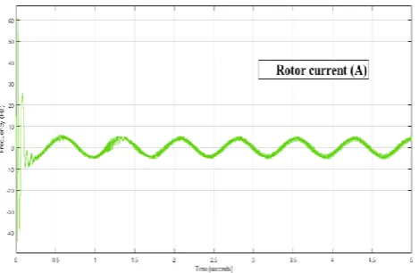
Figure9. Waveform of Rotor Current without gain after MATLAB Simulation
The α-β components for angle are found with the help of Clark’s transformation. The angle depends upon the voltage, fundamental frequency and time also. The variation of angle in the waveform for the frequency is shown in figure 10. The relation of angle, voltage, frequency and time is given by equation 8
α= tan-1(V
d / Vq) = 2πft = wt, where f = fundamental frequency
[image:4.595.52.287.52.205.2][18]………. Eq. [8]
Figure 10. Angle waveform for the frequency of 60 Hz
In figure 11 we represent the variation of electromagnetic torque with respect to different input torque ranges from 5-10
Figure11. Variation of Electromagnetic Torque
Nm and frequency 60 Hz. With the help of figure we can understand that initially the torque fluctuate in between the range (-30Nm to 50Nm) and after some value it become constant. The torque will fluctuate with respect to input speed and frequency.
The figure12 show the variation of speed with respect to the input speed. It shows that after 2 sec the speed is almost become constant.
Figure12. Variation of the Asynchronous speed in Waveform
VI. CONCLUSIONS
The following conclusions are drawn after reviewing the above mentioned literature:
1. With the help of above Simulation model we can easily analyzed the control of speed of the three phase induction motor on different parameters like increasing speed, voltage, frequency.
2. With this we easily input the speed with the help of mobile phone, keypad or knob. It will reduce the setting time of machine and increase the efficiency of the machine.
3. By using Variable frequency drive we easily control the speed and the motor will run on the desired speed rather than rated speed. It will reduce the chances of damaging the motor on high frequency because it is a self-adjusting drive. 4. PID controller automatically reduced the chance of error by Proportional, Integral and derivatives value. So it is easy to control the speed of three phase induction motor.
REFERENCES
1. Kalpakjian, “Manufacturing Engineering”, 4th Edition, Pearson, United States of America, 2007.
2. Santosh Gangwar and Dr. P.Sudhakar Rao,”Review on real time control of lathe machine during turning operations” ISSN: 2455-2585, vol. 5, issue 04, pp.47-51, 2019.
3. Randall L. Foulke, Principles and applications of Variable Frequency Drives NC AWNA. WEA Spring Conference New Bern, North Carolina April, 2009.
4. https://www.bing.com/images
5. Ned Mohan, Tore M. Unlaland and William P. Robbins Power electronics (converters, application and design) third edition, john wiley and sons INC.
6. Mohammad Alizadeh, Mahyar Masoumi, and Ehsan Ebrahim, ”Closed loop speed control of induction motor using constant V/F applying SPWM and SVM based inverter”, ISSN: 2249-8958, vol. 6, issue 5, pp. 234-241, 2017.
7. Prasanna Sagdeo, Shilpa Patil, Vipin kumar Meshram and Puja Zurale,” SVPWM controller for three phase inverter using PI controller operating under non-linear load”, ISSN: 2278-1021, vol. 4, issue-10, pp.41-44, 2015.
8. P.C.Sen Power Electronics McGraw-Hill Education Private Limited, Second edition 2009.
International Journal of Innovative Technology and Exploring Engineering (IJITEE) ISSN: 2278-3075, Volume-8 Issue-9 June, 2019
10. Aparna Sharma. Abhijit Singh and P.Yadav,” Analysis of 3 level SVPWM based open loop and closed loop V/F control of induction motor”, ISSN: 2278-0181, vol. 4, issue 4, pp.1362-1365, 2015. 11. http://lhp.co.in/index
12. Enemuoh F. O., Okafor E.E., Onuegbu J. C. and Agu V.N., “Modelling, Simulation and Performance analysis of a Variable Frequency Drive in speed control of induction motor”, ISSN- 2319-6491, vol. 3, issue 5, pp. 36-41, 2013.
13. https://in.mathworks.com/matlabcentral
14. Milan Kumar Ghevariya and Dr. Pramod S. Modi,” Comparison of SPWM and SVPWM based closed loop speed control of BLDC drive”, ISSN: 2319-7242, vol. 7, issue 10, pp. 24327-24332, 2015. 15. https://www.elprocus.com/mosfet-as-a-switch-circuit-diagram-free-c
ircuits/
16. Krupa Gandhi, K.L.Mokariya and Deepu karvat,” Simulation of PWM inverter for VFD application using MATLAB”, ISSN: 2278-800X, vol. 10, issue 4, pp. 94-103, 2014.
17. Matlab/Simulink model V-F induction motor
18. K. Vinoth Kumar, Prawin Angel Michael, Joseph P.John and Dr. S. Suresh kumar,” Simulation and comparison of SPWM and SVPWM control for three phase inverter”, ISSN: 1819-6608, vol. 5, pp. 61-74, 2010.
AUTHORS PROFILE
Km Santosh Gangwar born on 15/04/1988. I completed B.Tech from Ajay Kumar Garg Engineering College Ghaziabad. Presently I am a M.E. Scholar in National Institute of Technical Teachers Training and Research, has one review paper published in IJTIMES. And I have 6 years teaching experience.
Dr. P. Sudhakar Rao, Assistant Professor in Mechanical Engineering Department, NITTTR Chandigarh. He completed his P.Hd. from IIT Roorkee.