International Journal of Innovative Technology and Exploring Engineering (IJITEE) ISSN: 2278-3075, Volume-8 Issue-10, August 2019
Abstract: Electroporation is an effective phenomenon of inactivating viable pathogens present in the liquid food for pulsed electric field (PEF) applications. It is a technique which depends on applied electric field strength for causing pores on cell plasma membrane. The various parameters which affect the electroporation efficacy are, the electric field intensity, pulse width, number of pulses, pulse interval and the electrode. The electrode provides a contact between the high voltage pulse generator and the liquid food, and it plays an important role in getting the required inactivation outcome. The electric field distribution varies based on electrode designs. Parallel plate electrodes are generally used due to the uniform electric field it delivers in the inactivation area, where high possibility of microbial inactivation will occur. This paper analyses the effectiveness of round edged parallel plate electrodes immersed in water which provides uniform electric field distribution in the inactivation area. Analyses have been performed on electric field distribution through four kinds of materials such as glass, alumina, quartz and plexiglass, which contains these electrodes in the center filled with sterile water. The electrodes are circular, and edge smoothened and hence the field distribution is also analyzed on electrode edges. The distance between the electrodes including the surface material is kept at 5 mm. The diameter of the electrodes are 40 mm and the electric field simulations are implemented in ANSYS MAXWELL v 15.0. Based on results it is reported that alumina required less peak voltage for generating 20 kV/cm field strength (nominal field required for bacterial inactivation) when compared with other materials. Also alumina exhibited less reduction of field travelling through it, and resulted in 82% of field application in the inactivation area which is comparatively higher than other materials. The results indicate that alumina is highly recommended for future noninvasive pulsed electric field applications.
Index Terms: Noninvasive PEF applications, pulsed electric field, Surface materials, Water electrodes.
I. INTRODUCTION
Pulsed electric field (PEF) treatment has been prevailing for the past two decades as the successful nonthermal food preservation technique due to it’s low energy consumption, retaining of food’s quality attributes such as taste, color, freshness, texture and especially the nutritional qualities when compared with heat treatment methods [1]. The high voltage pulses can be delivered to liquid foods through electrodes where the cell inactivation takes place by means of electroporation phenomenon [2]. The configuration of
Revised Manuscript Received on August 02, 2019.
Ramya Ramaswamy, Department of EEE, BS Abdur Rahman Crescent Institute of Science and Technology, Chennai, India.
Dr. R. Raja Prabu, Department of EEE, BS Abdur Rahman Crescent Institute of Science and Technology, Chennai, India.
Dr. V. Gowrisree, Department of EEE, Anna university, Chennai, India.
electrodes and the electric field distribution inside the PEF treatment chamber is supposed to have a greater impact on bacterial inactivation. There are many electrode configurations available where parallel plate electrodes were used in initial studies, and stainless steel was used as the electrode material for most of the PEF applications [3-5]. The electric field distribution inside the PEF chamber depends on the configuration of the electrodes. Parallel plate electrodes provide more uniform electric field distribution in the inactivation area i.e., between two electrodes, where high possibility of inactivation takes place [6]. The main drawback of PEF treatment exists, when the frequency of electrode usage increases during every PEF treatment resulting in the release of metallic particles from the electrodes [4]. These metallic particles get mixed with the liquid food during the treatment which gives a metallic taste, which questions the safety of foods when consumed [4]. Recent research focuses on using noninvasive electrodes, where direct contact of liquid with electrodes will be prohibited so that the major drawback of PEF treatment i.e., electrolysis will be prevented. Such efforts include adhering high permittivity ceramic cylinders with the electrodes, metal coating on electrodes etc [7,8]. This paper focuses on application of high electric field through electrodes which are immersed in water for PEF applications. The applied peak voltage across the electrodes is 10 kV. Four kinds of surface materials are used for containing water where the electrodes are immersed in the center. By this arrangement, the electrodes are made noninvasive, where the electric field cannot be directly applied to the liquid food and will travel through the respective materials to reach the inactivation area. These materials include quartz, alumina, plexiglass and glass. Hence, direct contact of electrodes will be prevented paving a way for achieving successful noninvasive PEF applications. The electric field distribution in the inactivation area and the field reduction on the electrode edges are analyzed, which may be helpful for future noninvasive PEF applications using these materials.
II. MATERIALS AND METHODS
A. Electroporation
Electroporation is a technique where due to the application of high voltage short duration pulses of nanosecond to microsecond duration, temporary hydrophilic pores will be created on the surface of the cell plasma membrane.
Electric field Analysis of Water Electrodes for
Noninvasive Pulsed Electric field Applications
Here electric field plays a major role in inducing transmembrane potential of approximately 1V which is the minimum potential required to create pores on the membrane surface leading to cell inactivation [9,10]. The corresponding electric field responsible for inducing TMP of 1V is known as critical electric field Ec below which inactivation does not occur. This condition is known as reversible electroporation where the pores can reseal itself and survive after pulse application [9,10]. If the induced TMP increases greater than 1V, then the radius of the pores will become larger going beyond critical electric field leading to a condition where the cell cannot reseal its pores and survive. This condition is known as irreversible electroporation [9,10]. In our research, the electric field distribution is analysed through electrodes and the surface materials, so that the required field application can cause electroporation of cells embedded in liquid medium in the inactivation area under practical implementation.
B. Parallel plate electrodes
Fig. 1 shows the parallel plate electrode designed in ANSYS MAXWELL v 15. The diameter of the electrodes is 40 mm. The edges are smoothened to avoid electric field enhancement [6].
Fig 1. Parallel plate electrodes immersed in water
The electrodes are 5 mm apart (including the surface material adhered with the electrodes) and the distance gap can be varied based on specific electric field requirement. The diameter of the containing material is 100mm and height is 50 mm. The electric field generated between two parallel electrodes can be calculated theoretically as [11]
(1)
Where V is the charging voltage (Volts) and d is the distance between two electrodes (cm). The upper electrode is the high voltage, or the live electrode and the lower electrode is at ground potential. When a voltage is applied, a conducting path will be obtained from high voltage to ground electrode where high probability of inactivation is expected to take place. The electrodes are immersed in water to have temperature control during the treatment because temperature increase is a crucial factor in PEF, which should not exceed to create thermal effects on the liquid food. Hence temperature
should be maintained below pasteurisation temperature during PEF studies
.
C. Ansys Maxwell
The designed parallel electrodes are analyzed in ANSYS Maxwell v 15 [12]. It is a commercial software, which has been used in many fields of engineering. The ANSYS version 15.0 is used to analyze the electric field distribution of the designed electrode for the applied voltage. The three dimensional modelling will help to understand the electric field behavior before building a prototype.
D. Properties of materials used (i) Stainless Steel
The material used for the electrode in the simulation is stainless steel. The electrical properties considered for the material are its resistivity or conductivity and its relative permittivity. The resistivity and relative permittivity of the stainless steel used are 6.9 x 10 -7 m at C and 1 respectively [13]. This material is used as a state of art material in PEF applications. Stainless steel is a steel alloy containing high percentage of iron, chromium and nickel and has excellent corrosion resistant properties [13].
(ii) Sterile water
It is a clear, colourless, odourless, sterile, hypotonic, and nonpyrogenic liquid, which contains no bacteriostatic or antimicrobial agents. In this research, sterile water was used as a medium for immersing the electrodes.
(iii) Properties of water containing materials
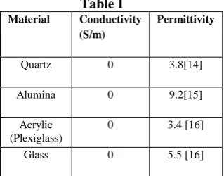
[image:2.595.46.273.348.534.2]Properties of containing materials having electrodes and water are fed to the model and meshed. The data are shown in Table I. The materials are basically nonconductive and hence conductivity is taken as zero.
Table I
Material Conductivity
(S/m)
Permittivity
Quartz 0 3.8[14]
Alumina 0 9.2[15]
Acrylic (Plexiglass)
0 3.4 [16]
Glass 0 5.5 [16]
III. RESULTS AND DISCUSSION
A. Electrode Design
[image:2.595.356.516.496.621.2]International Journal of Innovative Technology and Exploring Engineering (IJITEE) ISSN: 2278-3075, Volume-8 Issue-10, August 2019
Fig 2. Electric field distribution with plexiglass as surface material
The red color shows maximum field value of 20 kV/cm which can be present in the central circumferential region in the inactivation area where electrodes are present behind the surface material. Shades of blue color is for minimum field or even zero as given in the legend. The various colors between two extremes represent the electric field in between maximum and minimum values. These intermediate field variations can occur, due to change in properties at the junctions between the electrode and surface material. The maximum field gradually decreases to zero while reaching the sides of the chamber.
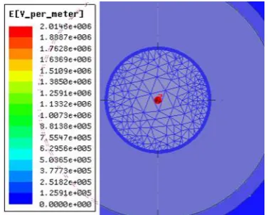
[image:3.595.58.222.72.200.2]When modeling the electrodes, the overlapping cannot be done between associated models. So, the electrodes which are modelled and placed inside the water are subtracted from the water body inside the containing material. Then the properties of each material are applied and meshed as shown in Fig 3.
Fig 3. Meshed top view of the electrode in water at 20 kV/cm
The high voltage electrode model is then assigned a nonzero excitation voltage where the potential for the ground electrode will be zero. All the simulations were run at a desired electric field intensity of 20kV/cm, which is the nominal electric field value required for bacterial inactivation [6]. The result thus obtained in solving the model can be interpreted in the form of change in electric field distribution with respect to distance in mm which are shown in Fig. 4a and 4b. The field distribution is observed from high voltage to ground electrode through each surface material chosen and also on the sides of the chamber.
a)
b)
Fig 4. a) Field from high voltage to ground electrode b) Field reduction on sides of the chamber
Observation I
In the data shown in Table II, the peak voltage required to obtain a desired field intensity of 20 kV/cm and percentage reduction of field from the point where field starts to reduce till the minimum field value obtained at the sides of the chamber are furnished. From this observation the performance of surface materials in obtaining 20 kV/cm electric field in the inactivation area can be understood.
Table II
Material Required peak
voltage to obtain 20
kV/cm in the
inactivation area
Percentage reduction of field on the chamber sides
Quartz 15.5 24
Alumina 12.5 21
Plexiglass 16 24
[image:3.595.55.244.419.570.2]The circular electrode has uniform distribution of electric field intensity in the inactivation area. The field distribution is compared when passing through four extreme materials. They are quartz, alumina, plexiglass and glass. Here, permittivity plays a major role in enabling the electric field through each material to reach the inactivation area. From the results, it is found that alumina requires a lesser peak voltage when compared with other materials to provide a uniform field of 20 kV/cm in the inactivation area. The electric field can be viewed not only on the inactivation area from high voltage to ground electrode (vertical direction), but also can be monitored on the sides of the chamber (horizontal presence of field gradients). Out of the materials used in this study, Alumina and glass are found to be nontoxic and can be used as food safety materials. Since the electrodes are round edged and smoothened, the drawback of electric field enhancement can be greatly avoided. As the permittivity of alumina is higher than glass, alumina has more advantage over field reaching the inactivation area through it, but the cost of the former is greater than the later. The maximum electric field is found around the center area of the treatment region and gradually reduces as the field reaches the chamber sides.
Observation II
Under observation I, peak voltage was changed accordingly to obtain a desired field value of 20 kV/cm in the simulation, which was considered as the nominal field required for bacterial inactivation. Under observation II, when compared with electrodes without surface material, a 10 kV of peak voltage is sufficient to obtain 20 kV/cm of field in the inactivation area at a distance of 5mm between the electrodes. But, if peak value of 10 kV was applied across the electrodes under the presence of surface material, 100% field application cannot be achieved. However, electric field lesser than 20 kV/cm can still be used under laboratory scale for successful microbial inactivation. The data is shown in Table III. This will enhance the understanding on percentage field reduction from high voltage to ground electrode when it travels through the surface material and will enable us to decide the suitability of material for noninvasive PEF applications.
Table III
Material Applied
peak voltage
Generated
field on
inactivation area (kV/cm) Percentage Field reduction
from high
voltage to ground electrode through surface material Percentage Field reduction on the chamber sides
Alumina
10 kV
16.42 17.9 23
Glass 14.7 26.5 23
Quartz 13.07 34.6 24
Plexiglass 12.6 37 24.8
From the results, it is understood that Alumina has a lesser percentage reduction of field when it reaches the inactivation area from high voltage to ground electrode. i.e., when compared with 100% field application using electrodes without surface material, alumina reported only 17.9% of field reduction when it reaches the inactivation area resulting
in 82% of field application when compared with other materials. Hence, based on the results alumina can be considered as the surface material most suitable for noninvasive PEF applications, and will efficiently electroporate the viable pathogens present in the suspension medium using uniform field applications.
IV. CONCLUSION
Parallel plate round edged electrodes in water contained in four kinds of surface materials are designed and analyzed in ANSYS MAXWELL. It shows uniform distribution of electric field in the inactivation area. The aim of this research is to analyze the properties of surface materials on enabling maximum field application to reach the inactivation area for successful noninvasive PEF applications. It is found that alumina achieves 82% of field application in the inactivation area, which is comparatively higher than other materials. Also, it requires lesser peak voltage to obtain a nominal field value of 20 kV/cm for bacterial inactivation. This confirms the suitability of the material for future successful noninvasive PEF applications.
REFERENCES
1. G.V. Barbosa Canovas, M.M.G. Nieto, U.R. Pothakamury, B.G. Swanson, “Fundamentals of high intensity pulsed electric fields,” in Preservation of foods with pulsed electric fields, San Diego, CA: Academic Press, 1999, pp. 1-2.
2. J. C. Weaver, "Electroporation of cells and tissues," IEEE Transactions on Plasma Science, vol. 28, no. 1, pp. 24-33, Feb. 2000. DOI: 10.1109/27.842820.
3. C. Schultheiss, H. Bluhm, H.G. Mayer, M. Kern, T. Michelberger, G. Witte, "Processing of sugar beets with pulsed-electric fields," IEEE Transactions on Plasma Science, vol. 30, no. 4, pp. 1547-1551, Aug.
2002
.
DOI: 10.1109/TPS.2002.8042124. A. Gad and S. H. Jayaram, “Effect of electric pulse parameters on releasing metallic particles from stainless steel electrodes during PEF processing of milk,” IEEE Transactions on Industry Applications, vol. 50, no. 2, pp. 1402–1409, Mar./Apr. 2014. DOI: 10.1109/TIA.2013.2278424
5. S. Qin et al., "Pulsed electric field treatment of saccharomyces cerevisiae using different waveforms," in IEEE Transactions on Dielectrics and Electrical Insulation, vol. 22, no. 4, pp. 1841-1848, August 2015. DOI: 10.1109/TDEI.2015.005152
6. Bai-Lin Qin, Qinghua Zhang, G. V. Barbosa-Canovas, B. G. Swanson and P. D. Pedrow, "Inactivation of microorganisms by pulsed electric fields of different voltage waveforms," in IEEE Transactions on Dielectrics and Electrical Insulation, vol. 1, no. 6, pp. 1047-1057, Dec. 1994. DOI: 10.1109/94.368658
7. B. M. Novac et al., "Non-invasive pulsed electric field food processing: Proof-of-principle experiments," 2012 IEEE International Power Modulator and High Voltage Conference (IPMHVC), San Diego, CA, 2012, pp. 528-531.
8. A. Gad, S. H. Jayaram and M. Pritzker, "Performance of Electrode Materials During Food Processing by Pulsed Electric Fields," in IEEE Transactions on Plasma Science, vol. 42, no. 10, pp. 3161-3166, Oct. 2014. DOI: 10.1109/TPS.2014.2312711
9. K. H. Schoenbach, R. P. Joshi, R. H. Stark, F. C. Dobbs and S. J. Beebe, "Bacterial decontamination of liquids with pulsed electric fields," in IEEE Transactions on Dielectrics and Electrical Insulation, vol. 7, no. 5, pp. 637-645, Oct. 2000. DOI: 10.1109/94.879359
International Journal of Innovative Technology and Exploring Engineering (IJITEE) ISSN: 2278-3075, Volume-8 Issue-10, August 2019
11. G.V. Barbosa Canovas, M.M.G. Nieto, U.R. Pothakamury, B.G. Swanson, “Fundamentals of high intensity pulsed electric fields,” in Preservation of foods with pulsed electric fields, San Diego, CA: Academic Press, 1999, pp. 7.
12. https://www.ansys.com/en-in/products/electronics/ansys-maxwell
13. J.R. Davis, “Introduction to stainless steels,” in Stainless Steels, OH: ASM International, 1994, pp 10.
14. P.A. Sarafis, A.G. Nassiopoulou, “Dielectric properties of porous silicon for use as a substrate for the on-chip integration of millimeter-wave devices in the frequency range 140 to 210 GHz,” Nanoscale Research Letters, 2014. DOI: 4022. 10.1186/1556-276X-9-418.
15. Catalogue, “Metals, Alloys, Compounds, Ceramics, Polymers, Composites,” Goodfellow Cambridge Ltd, 1993/94.
16. Graham Brodie, Mohan V. Jacob and Peter Farrell, “Techniques for measuring dielectric properties,” in Microwave and Radio-Frequency Technologies in Agriculture, Berlin: De Gruyter open Ltd, 2015, pp 73-74.
AUTHORS PROFILE
Ms. Ramya Ramaswamy was born in Chennai, india in 1982. She received the B.E. degree in Electrical and Electronics Engineering from University of Madras, Chennai, India, in 2003 and the M.Engg. degree in Electrical and Computer Engineering from Morgan State University, Baltimore, USA, in 2009. She is currently pursuing the Ph.D. degree in High Voltage Engineering from B.S. Abdur Rahman Crescent Institute of Science and Technology, Chennai, India.
From 2008 to 2009, she was a Research Assistant with Morgan School of Engineering, Baltimore, USA. Her research interests include Modeling and simulation of RF devices, High Voltage Engineering, Life Sciences, Food preservation using Pulsed Electric Field.
Dr. Raja Prabu Ramachandran, a member of IEEE, USA received the B.E degree in Electrical and Electronics Engineering from Annamalai University, Chidambaram, India in 1988 and M.E degree in Power System Engineering from Annamalai University, Chidambaram, India in 1990. He received the Ph.D. degree in High Voltage Engineering from College of Engineering, Anna University, Chennai, India in 2006.
He has been serving as a Professor with Department of Electrical and Electronics Engineering, B.S. Abdur Rahman Crescent University, Chennai, India. He has coauthored a book, and an author of more than 75 research articles, and has been an investigator in many government funded projects. His research interests include Bioelectrics, Outdoor insulators, Power quality, Digital protection and Nano dielectrics.
.
Dr. V. Gowrisree, received the B.E. in Electrical and Electronics Engineering from College of Engineering, Anna University, Chennai, India in 1992 and M.E. degree in High Voltage Engineering from College of Engineering, Anna University, Chennai, india in 1997. She received the Ph.D. degree in High Voltage Engineering from College of Engineering, Anna University, Chennai, India in 2008.