COMMISSION OF THE EUROPEAN COMMUNITIES
nuclear science and technology
The Community's R & D Programme on
radioactive waste management and storage
(Second annual progress report)
COMMISSION OF THE EUROPEAN COMMUNITIES
nuclear science and technology
The Community's R & D Programme on
radioactive waste management and storage
(Second annual progress report)
Directorate General for
Research, Science and Education, Brussels
Published by the
COMMISSION OF THE EUROPEAN COMMUNITIES Directorate-General
'Scientific and Technical Information and Information Management' Bâtiment Jean Monnet
L U X E M B O U R G
LEGAL NOTICE
Neither the Commission of the European Communities nor any person acting on behalf of the Commission is responsible for the use which might be made of the following
information
A bibliographical slip can be found at the end of this volume
© Copyright ECSC-EEC-EAEC, Brussels-Luxembourg, 1978 Printed in Belgium
F O R E W O R D
This is the second progress report concerning the programme on radioactive waste management and storage
(indirect action) of the Commission of the European Communities. It covers the year 1977 and follows the
1976 Annual Report.
The five year programme, ending 3 1 December 1979, was approved by the Council of Ministers on 26 June 1975.
The Council decision is based on the two following considerations :
- "Nuclear energy is bound in the near future to be" come one of the main sources of energy alongside tradi-tional sources, and its specific nature requires perma-nent monitoring of its potential effects and improved measures and research to protect the environment;
- The development of nuclear energy inevitably involves the production of radioactive waste and it is therefore essential to find effective means for ensuring the safety and protection of both man and his environment against the potential hazards involved in the management of such waste",
The programme is carried out by contracts on an expense sharing basis with public or private qualified agencies of the Community; the Commission's financial participation amounts to 19,16 million units of account A Consultative Committee of national experts nominated by their governments assists the Commission for the ma-nagement of the programme.
The aim of the programme, as indicated in the annex of the Council decision, is the joint development and perfecting of a system of management of radioactive waste produced by the nuclear industry which, at its various
stages, affords man and his environment the best pro-tection possible.
O.J. Nr. L 178/28, 9.7.1975
The principal items of the programme are the follo wing :
A. Work to solve certain technological problems posed by the processing, storage and disposal of radioactive waste.
Processing :
Medium activity solid waste : coating with plastic resins ;
Highactivity solid waste s decontamination and con ditioning of irradiated fuel element cladding;
Highactivity solid, waste : immobilization of calci
ned waste from fission products in a metal»matrix ;
Plutoniumcontaminated solid waste : incineration process ;
Comparative study of the properties of various mate rials suitable for the immobilization of highactivity waste.
Storage and disposal :
Storage of solidified radioactive waste in engineered structure ;
Disposal of radioactive waste in suitable geological formations, including those formations currently being studied;
Storage of gaseous waste.
Study of an advanced management model :
Separation and recycling of longlife waste (actinides).
B. Work contributing towards the definition of a general
framework (legal, administrative, financial) for the implementation of radioactive waste storage and d i s posal measures :
Review of problems posed by the management of radio active waste which could not be solved under existing international, legal, administrative and financial provisions and proposals for solutions;
Study of principles which should govern the management of radioactive waste.
The professional staff in charge of the management of the pro gramme during 1977 were :
B. Huber (partly) CEC
Ρ c.¡m„„ DirectorateGeneral XII
Research, Science and Education
P. Venet 200 rue de la loi
Β 1049 Brussels
T h e p r o g r a m m e is c l o s e l y c o o r d i n a t e d w i t h t h e a c t i v i t i e s r e l a t e d to t h e r a d i o a c t i v e w a s t e m a n a g e m e n t c o n d u c t e d by t h e C o m m o n R e s e a r c h C e n t e r of t h e CEC w i t h i n its p l u r i a n n u a l R e s e a r c h p r o g r a m m e ( d i r e c t a c t i o n ) .
S. O r l o w s k i H e a d , d i v i s i o n
C O N T E N T S
FOREWORD
TREATMENT OF LOW AND MEDIUM LEVEL WASTE \
1.1. Introduction 1 1.2. Mobile plants for resin fijnbedding of reactor \
waste (Steag Kernenergie)
1.3. Stationary resin embedding pilot plant (SENA) 4
HIGH-ACTIVITY SOLID WASTE : DECONTAMINATION AND
CONDITIONING OF IRRADIATED FUEL ELEMENTS CLADDINGS
2.1. Introduction 7 2.2. Press compaction and incapsulation by low-melting n
alloy (CEN/SCK)
2.3. Conditioning by rolling and embedding in concrete 9 (KFK Karlsruhe)
2.4. Decontamination and conditioning by fusion (CEA, Marcoule)
2.5. Characterization of the radioactivity in different
cladding wastes (UKAEA, Harwell) 1D
2.6. Assessment of the various types of cladding 2I
IMMOBILIZATION OF FISSION PRODUCT CALCES IN A METALLIC MATRIX
13
35
TREATMENT OF PU-CONTAMINATED COMBUSTIBLE WASTE 36
4.1. Introduction 36 4.2. High temperature incineration (CEN/SCK) 3^
4.3. Incineration in molten salts (Agip Nucleare) ci
4.4. Acid digestion process (KFK, FRG) 54 4.5. Process for the pyrolysis of Pu-contaminated ¿ Q
combustible solid waste (UKAEA)
4.6. Critical factors in the recovery of plutonium ¿4 (UKAEA )
4.7. Radiation assisted incineration study (Gravatom) D8
5 TESTING AND EVALUATION OF SOLIDIFICATION SUBS- 81 TANCES FOR HIGH LEVEL WASTE
5.1. Introduction 81 5.2. Devitrification effect on physical and chemical 81
5.3. Analysis Of the effects of leaching and ra- 84 diation (UKAEA)
5.4. Leach tests with fission product bearing glass 88 blocks (CEA, Marcoule)
5.5. Complementary actions 88
ENGINEERED STORAGE FOR SOLIDIFIED HIGH LEVEL WASTE 98
6.1. Scope and state of the programme 98 6.2. Common reference data and options 98
6.3. Programme of work for 1978 101
6.4. Reference JQJ
DISPOSAL OF RADIOACTIVE WASTE IN GEOLOGICAL 1Q8 FORMATIONS
7.1. Introduction 108 7.2. Development of an experimental repository field -j. 11
within the Asse salt mine for high level waste glasses (GFK)
7.3. Disposal of radioactive waste in salt domes (ECN) 125 7.4. Disposal of radioactive waste in deep clay forma- 129
tions (CEN/SCK)
7.5. Evaluation of the possibilities of disposing of 136 long-lived radioactive waste and/or high activity
wastes in clay formations (CNEN)
7.6. Disposal of radioactive waste in hard rock forma- 140 tions (CEA)
7.7. Investigation of feasibility of disposal into 143 geological formations (UKAEA)
STORAGE OF GASEOUS WASTE 178 8.1. General introduction 178 8.2. Kripton incorporation in a metallic matrix (UKAEA) 178
8.3. Kripton storage in pressurized cylinders (KFA Jülich) 182 8.4. Storage of charcoal absorbed Kripton in
pressu-rized cylinders (CEN/SCK)
8.5. Feasibility of Kripton sea disposal (KFA Jülich and 185 ECN Petten)
8.6. Kripton immobilization by incapsulation in zeolites 190 (NUKEM)
8.7. Screening study on tritium immobilization (UKAEA) 191 8.8. Iodine incorporation in low melting glass (Le Verre
Fluoré - S.A.R.L. Rennes) 194 8.9. lodine incorporation in epoxy resins (CEN/SCK) 195
184
10 REVIEW OF PROBLEMS RAISED BY RADIOACTIVE WASTE
MANAGEMENT WHICH COULD NOT BE SOLVED WITHIN THE 198 FRAMEWORK OF THE EXISTING LEGAL, ADMINISTRATIVE AND
FINANCIAL PROVISIONS
11 FINANCIAL AND ADMINISTRATIVE ANNEX 203
12 PUBLICATION LIST 2 ,_
13 LIST OF THE MEMBERS OF THE ADVISORY COMMITTEE FOR PROGRAMME MANAGEMENT
2 16
— 1 —
TREATMENT OF LOW AND MEDIUM LEVEL WASTES
1.1. I n t r o d u c t i o n
Liquid wastes from virtually all operations of the nuclear fuel cycle against immobilization for safe transportation and storage.
The low and medium liquid level waste arising from LWR largely consists of evaporator sludges, ion ex-change resins and filter aids. Similar wastes are produced in certain operation of reprocessing plants. The presently applied immobilization techniques,
using concrete or bitumen as metric, have not been entirely satisfactory. In certain cases solidifi-cation of the concrete was not assured or the waste volume was considerably increased. Bitumen embed-ding, among other shortcomings, has off-gas problems/ uses an inflammable matrix and produces solidified wastes with low mechanic strength.
The immobilization in thermal setting resins, e.g. polythene, polyester or epoxy should at least for a wide range of low and medium level liquid wastes render waste products with improved characteristics for transport and disposal.
1.2. M o b i l e P i l o t P l a n t s f o r R e s i n E m b e d d i n g o f R e a c t o r W a s t e s
(Steag Kernenergie Gmbh) 1.2.1. ubjective and_Scoge
Steag Kernenergie Gmbh, the contractant, was and still is the only firm to commercially condition radioactive bead ion exchange resins by embedding this type of reactor waste in polystyrene resins. The objective of the R & D Contract in this pro-gramme was to study the possibilities and develop a technology permitting the embedding of other reactor wastes (e.g. evaporator sludges, filter candles, powder resins) in a suitable polymer ma-trix .
The programme was intended to proceed in 5 stages : a) pieliminary investigations (product criteria,
characteristics of the wastes);
b) study and choice of candidate resins and con-ditioning methods;
c) laboratory studies and technical experiments with inactive and active wastes;
d) operation of experimental pilot plants;
— 2 —
1.2.2. Preliminary Investigation
The following investigations were carried out a) The various type
viewed in order wastes for which was advantageous b) A set of prelimi tions of accepta of the product w c) Safety and opera immobilization s first list of cr d) The various type
these criteria a tive wastes were
s of reactor wastes were re to determine the range of
the resin fixation technique
7
nary requirements and condi-nce for storage and disposal as drawn up ;
tional characteristics of the ubstances were studied and a isteria was compiled;
s of resins were examined against nd exploratory tests with
inac-undertaken.
1.2.3. Results
Reactor wastes
Of the wastes produc solid incombustible, or liquid wastes, on be considered as mos ble wastes (absorber measuring devices et for organic polymers e.g. contaminated cl are generally of sue can be conditioned a The low active liqui ly be conditioned, b prior to incorporati of these wastes prod LWRs are, according lower than assumed i rature.
The survey shows tha only about 50 m /a o form of filter aids
1-3 m /a of medium a resin.
ed by light water reactors : solid combustible and wet ly the latter category should t of the solid
incombusti-and control rods, in core c.) are normally too active
and the solid combustibles : othing and cleaning material h low activity, that they nd stored without fixation, d or wet wastes can general ut almost all require drying on into resins. The amounts uced by the modern large to a STEAG survey, somewhat n some of the recent
lite-t a 1200 MWe PWR produces f low active wet waste in and evaporator sludges and ctive spent ion exchange
b) Quality and Safety Criteria of the Product The most important c
MLW immobilization ρ - high chemical stab
substance against lutions;
- high leach resista - stability against - chemically and bio
sition products; - no liquid or gaseo
haracteristics for LLW and roducts were found to be : ility of the immobilization water and various salt
so-nce of the waste product; thermal effects;
logically safe
— 3 —
- low flammability;
- no violent chemical reaction;
- high resistance against bacterial
decompo-sition, fermentation and other forms of decay. The second group of characteristics, listing se-cond priority properties was also drawn up. These included such physical properties as softening
point, density, mechanical strength, thermal conductivity and homogeneity of the product.
c) Safety and ease of handling of the bonding resins In addition to the waste product criteria the polymers or other immobilization substances should be safe and convenient to handle in a reactor waste treatment plant.
The main requirements in these aspects appear to be :
- low viscosity; - low volatility; - high flame point;
- low adhesion tendency; - low toxicity?
- low specific reaction heat;
- good control for the polymerisation; - good stability during storage.
d) Choice of resins
First series of tests with polystyrene, polyester and epoxy resins have been carried out but nume-rical results are not yet available. A more qualitative comparison of the three products is presented in table 1.
Property of immobilizing resin Polystyrene Polyester Epoxy
Leaching resistance (hardened) Fire hazard
Reaction heat Vola tility Toxicity Viscosity
Capacity to absorb waste moisture
high high high high high low high
high high medium medium high high low
— 4
Other products - polyuremethanesjand resin - de-ment systems were also considered. First tests with polyuremethane confirmed that the leach re-sistance of this type of polymer is comparati-vely poor .
The cement-polymer systems however promise to have all the advantages of the cement fixation
(low fire hazard, good moisture absorption) without the disadvantages (mechanical strength, leach
resistance). 1.2.4. Conclusions
The polystyrene resin embedding, originally favou-red by Steag, does not, in the view of the contrac-tor have a sufficient development potential to war-rant further effort on this contract. The main rea-sons for this conclusion are :
- Handling problems with the raw resins (fire and explosion hazard of styrene, toxicity);
- Processing difficulties : nearly all wet reactor wastes require preparatory treatment, generally drying, in order to obtain a satisfactory product; - Economics
The progress achieved in improving cement conditio-ning methods and their products seriously threatens the economic viability of the competing resin based conditioning systems at least in the FRG, where the disposal space in the ASSE Salt mine is not the major cost factor.
- Radiation shielding
Due to the many process operations, frequent main-tenance and often low production rates of the resin conditioning plant, occupational radiation exposure is relatively high.
The Commission and Steag will, in the beginning of 1978, negotiate the discontinuation of the present programme.
1.3. S t a t i o n a r y R e s i n E m b e d d i n g P i l o t P l a n t (SENA)
1.3.1. Objectives
The aim of the second R & D contract on low and medium level waste conditioning is to build and operate an active pilot plant for resin fixation of the reactor wastes on the site of the SENA PWR at Chooz and to test and evaluate the characteristics of the conditioned waste product in respect to
δ
-1. 3. 2. The Development P^g^amme
The R & D programme implemented under the contract consists of the following main actions :
- definition of the conditioning process; - design and construction of the pilot plant;
- commissioning and operation of the pilot plant; - testing and evaluation of the products.
1.3.2.1. The Conditioning Process
The process of fixing wet reactor waste in thermo setting resins as patented by the SENA will prima rily be applied to the evaporator sludges. These wet residues will first undergo chemical pre-treat ment, in order to fix the principal radioisotopes Cs and Co to insoluble compounds* There upon they are dried in a continuous-rotating drum dryer and added to the polymer resin in the final packing drum. -The dryer off gas is sent through a scrubber
(DF 10 to 10 ) and a condenser before entering the reactor off gas system. The mixture is then stirred and the accelerator and catalyst are added to start the setting.
The waste-resin mixture then hardens within hours.
1.3.2.2. The Reactor Wastes
The amount of wastes that will be treated in the pi lot plant are :
3 3 - ca. 30 m /a of primary wastes (50 Ci/m ) ;
3 3 - ca. 15 m /a of miscellaneous wastes (1 Ci/m ) .
The primary wastes essentially consist of sodium borate (200 g/1) and boric acid (130 g/1) and con
tain the active isotopes C rc, , Co.. . J,.,, Cs,. ,,
* 51 60' 131 134
C S1 3 7 '
The miscellaneous wastes will contain 100-200 g/1 of various solid residues of detergents, deconta mination products, sodium borate etc.
1.3.2.3. The Pilot Plant
A pilot plant applying this CEA process will be built commissioned and operated with active waste on the site of the Chooz PWR. The plant will condition the wastes from the reactors effluent treatment facilities and produce canned waste blocks accep table for transport and storage.
— Θ
-Ι.3.2.4. Commissioning
At the end of the construction period a series of tests with inactive simulated wastes will provide opportunity for systematic trials at various ope rating conditions and waste compositions.
1.3.2.5. Operation
The last eight months of the programme will be devo ted to active operation under representative condi tions ,
All operating parameters, inspection and maintenan ce results as well as occupational exposure to radia' tion and, if any, toxic substances will be recorded and evaluated.
1.3.3. Product_Characteristics
A special study will establish the requirements for transport and storage of the waste product.
Production and, to a certain extent, experimental samples from the pilot plant will be tested and assessed against these characteristics.
The product evaluation study will also compare the relevant properties of the SENA product with those achieved with cement and bitumen on similar wastes. Statistic analysis of the quality control of the product will provide information on the effects of variations in operating conditions and on the con sistency of the production.
1.3.4-j Present State of Advancement
Work on preparing the site has begun in summer 1977 and, at the end of 1977, building work was reported to be progressing to schedule.
The principal target dates for the work in 1978 are Completion of project definition and of technologi cal tests : 31 May 1978;
Completion of building and civil engineering : 30 Oc tober 1978;
HIGH-ACTIVITY SOLID WASTE : DECONTAMINATION AND CONDITIONING OF IRRADIATED FUEL ELEMENT CLADDINGS
2.1. I n t r o d u c t
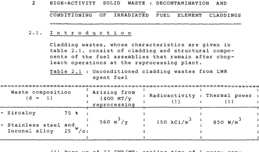
[image:19.595.34.556.81.387.2]Cladding wastes, whose characteristics are given in table 2.1. consist of cladding and structural compo-nents of the fuel assemblies that remain after chop-leach operations at the reprocessing plant.
Table 2.1 : Unconditioned cladding wastes from LWR spent fuel
Waste composition
(d = 1) Arising from 1400 MT/y reprocessing
Radioactivity (1).
Thermal power (1)
Zircaloy 75 %
Stainless steel and 560 m /y 150 kCi/m" w
Incone! alloy 25 /o
850 W/m"
(1) Burn up of 33 GWD/MT; cooling time of 1 year; con-tamination by 0.5 % of total spent fuel.
Conditioning processes, combining, if possible, an ap-propriate immobilization of radioactivity for long-term disposal with a substantial volume reduction, are needed for this waste.
2.2. P r e s s C o m p a c t i o n a n d E n c a p s u-l a t i o n b y L o w-M e 1 t i n g _A_ 1 JL_o y
(CEÅ/SCK MÖT)
Assembly extremities- are assumed to be regarded as a non-waste. The rest of cladding waste will be mecha-nically compacted into blocks and placed in a special basket. The remaining voids will be filled up with a corrosion resistant lead alloy by casting at about 723 °K. The research programme for the development of this conditioning method has been already descri-bed (1) .
2.2.1. Assessment_of Filling Allocs
Lead-tin and lead-antinomy alloys were selected as candidate filling materials. The corrosion resis-tance of those alloys may be improved by small addi-tions of tellurium or calcium.
— 8 —
formation has been simulated. The results in water environment (table 2.2) show the smallest corrosion rates in the case of ground water whose impurities form a protective layer or act as corrosion inhibi-tors .
. 2
Table 2.2 : Weight changes (mg/cm ) of lead alloys after exposure to different environments at 322 K.
Alloy Pb Pb-Zr'-Mg' Pb-Te Pb-Sb Pb-Ag > Ground water (+)
15 days - 0.037 - 0.035 + 0.186 + 0.185 0 - 0.072 0 - 0.019 0 + 0.019 3 months - 0.018 - 0.059 + 0.186 + 0.148 0 - 0.062 0 + 0.06 9 + 0.29 + 0.24
Déminer a 1 i zed water
Saturated with air : Absence of 15 days
- 18.18 - 17 .79 - 13.08 - 18.59 - 35.75 - 33 .28 - 16.76 - 16.38 - 6.76 - 2.64 3 months - 33.99 - 35.51 - 18.48 - 24.58 - 52.32 - 49.80 - 26.15 - 28 .19 - 9.11 - 13.18
2 . 5 months + 0.626 - 6 .67 - 5 .87 + 2 .27 - 9.74 -11 .73 + 1 .93 + 1.16 -39.00 -39.02 Humid clay atmosphere 1 month
+ 0. 14
+ 0.29
+ 0.14
+ 0.14
+ 6.83
2.2.1.2. Interaction of the Filling Alloy with. Cladding Waste and with Canister Materials
The compatibility of a Pb-1.5 w/o Sb alloy with zircaloy 4 and AISI 304 (potential canister mate-rials) is being evaluated after casting under vacuum at 723 K and long-term heat treatments up to 373 K. Attack of AISI 304 at the interface is caused by
alloy impurities such as Cu, Ag, Zn and Cd. No reaction was observed in the case of Zircaloy-4. 2.2.1.3. Influence of Filling Alloy on the Mechanical
Properties of the Canister Material
2.2.2. Development of the Conditioning Process 2.2.2.1. Compaction
Compaction tests have been performed by means of an extrusion press on unirradiated stainless steel and zj.rcaloy-4 cladding tubes. The results of these tests are graphically represented in fig. 2.2.1. The
compact diameter and the filling height (Ho) only have a minor influence on the obtained volume reduction.
Fig. 2.2.2 shows a typical example of compacted zircaloy tubes.
2.2.2.2. Embedding in Low Melting Alloys
Embedding tests of compacted zircaloy chops have been performed with Pb-1.5 % Sb as filling alloy by air and by vacuum casting at 723 'K. Vacuum casting (fig. 2.2.3) results in a much better fil-ling (1.5 - 3.5 % rest porosity) in comparison to air casting (15 - 18 % rest porosity). Generally a good contact between zircaloy and lead alloy has been observed and no open porosities or crevice pro-pagation have been found.
2.2.3. Conceptual Development
A preliminary concept has been based on a compact unit with capacities from 1500 to 3000 tons/a and producing compacted waste briquettes of 34 cm
diameter and 6 cm height. About 3600 loadings have to be compacted annually by a unit of this size in a 300 MTU per year reprocessing plant which would require a smaller press.
Press constructors have been contacted to evaluate the realization of a press unit in a hot cell at reasonable costs.
A conceptual design of a waste canister, which can be used as mould for casting of filling alloy, has been completed (200 cm length, 35 cm internal dia-meter, 3 mm wall thickness).
2.3. C o n d i t i o n i n g b y R o l l i n g a n d E m b e d d i n g i n C o n c r e t e (KFK
-Karlsruhe)
The method consists in incorporating in concrete the hulls whose volume is reduced by rolling press and the structural materials. The process will be developed and optimized by inactive tests at a pilot plant. The research includes the conceptual
— 10 —
2.3.1. Process_Development_and_Pilot_Plant Conception The rolling characteristics of inactive hulls were
studied at a laboratory press. Zircaloy4 hulls (10.75 χ 0.72 χ 50 mm) may be compacted till about 45 % of their theoretical density by single piece feeding with a deforming force of not more than 16 kN. After rolling three times about 30 % of hull pieces were longitudinally broken. 0.03 % fi
nes were produced. The design of a half scale
compacting unity (fig. 2.3.1) for cold tests has
been started. The cladding wastes are discharged
from a 400 liter container (A) into the feeding hopper (B). By means of a vibrating runner (C) the structural pieces, which are directly conveyed to the drum (G) containing the fluid concrete, are separated from the small pieces and hulls. The latter will, one by one, reach the compacting rolls
(E) through a dosing gear (H). The compacted pie ces will then fall into the drum (G).
2.3.2. Examination of Conditioned Wastes for Disposal
2.3.2.1. Hydrogen and Water Release
Physical and chemical reactions were examined on various concrete and zircaloy (fines) concrete mixtures, assuming that the waste temperature does not exceed 100 °C. Some tests were extended up to 400 °C to consider accident conditions.
Hydrogen is released by :
Thermal effect
Different concrete mixtures were tested at tempe rature up to 400 °C and the results condensed in a graph are given in fig. 2.3.2. Concrete with
additions at 200 °C already produced a H release
rate, which may lead to an inflammable and explo sive gas mixture.
Water zirconium reaction
Zirconium shows a high reactivity with the water present in concrete. Measurements were carried out on H release from a zirconium finesconcrete mixture as a function of temperature, zirconium
content and duration of the experiment (fig. 2.3.3) . Concrete additions seem to favour the reaction.
Water radiolysis
The water present in concrete undergoes the follo wing radiolytical reaction :
3 H O ^=à H° + 0H° + H + H O
— 11 —
50, 100 and 200 Mrad.
The first results indicate H releases of 2.2 6.5J01/g concrete per Mrad corresponding to 40 70 % of the produced hydrogen.
Water
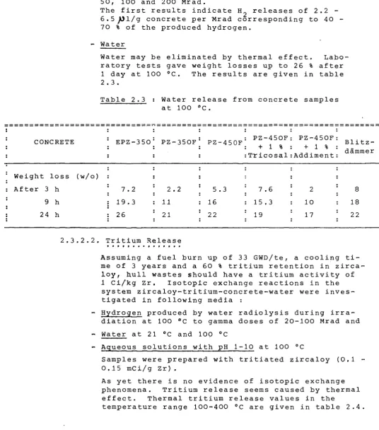
Water may be eliminated by thermal effect. Labo·
ratory tests gave weight losses up to 26 % after 1 day at 100 °C. The results are given in table 2.3.
Table 2.3 : Water release from concrete samples at 100 °C.
CONCRETE : EPZ350
Weight loss (w/o) :
: After 3 h \ 7.2
9 h : 19.3
: 24 h : 26
PZ350F
2.2 11 21
PZ450F
5 .3 16 22
PZ450F: PZ450F + 1 % : + 1 % Tricosal:Addiment
7.6 2
15.3 : 10
19 \ 17
Blitz '[
dämmer
8
18 :
22
2.3.2.2. Tritium Release
Assuming a fuel burn up of 33 GWD/te, a cooling ti me of 3 years and a 60 % tritium retention in zirca
loy, hull wastes should have a tritium activity of
1 Ci/kg Zr. Isotopie exchange reactions in the
system zircaloytritiumconcretewater were inves tigated in following media :
Hydrogen produced by water radiolysis during irra diation at 100 °C to gamma doses of 20100 Mrad and Water at 21 °C and 100 °C
Aqueous solutions with pH 110 at 100 °C
Samples were prepared with tritiated zircaloy (0.1 ■ 0.15 mCi/g Z r ) .
As yet there is no evidence of isotopie exchange
phenomena. Tritium release seems caused by thermal
effect. Thermal tritium release values in the
[image:23.595.17.554.79.688.2]— 12
Table 2.4 : Tritium release from concrete overcoated tritiated zircaloy hulls at various tem peratures and experimentation time.
Sample Nr Temperature
(°C)
Experimentation time (h)Relative release rate (Ci/Ci day)
2; 3; 4 6 100 300 300 400 400 24 24 150 24 150
4.1 - 6.7 x- 10 3 .6 χ io"3
-5
9.8 χ 10 1.1 χ 10 2.1 χ 10
-4 -2 -3
2.3.2.3. Mechanical Stability of Conditioned Wastes
The compression strength has been determined on
specimens of hulls (10.8 -χ 0.8 χ 50 mm) incor
porated in concrete (PZ - 350 + 1 % Tricosal) : 2
Unoompacted Zircaloy 4215 N/cm 2 Compacted Zircaloy 2880 N/cm Concrete specimen (as
reference) 3490 N/cm'
2.3.2.4. Thermal Conductivity of Conditioned Wastes
The thermal conductivity of the heterogeneous con crete-waste system was theoretically estimated for different compaction grades, and orientations of the hulls. At a compaction of hulls to 45 % of their theoretical density the thermal conductivity va lues were in the range 0,057 - 0,064 W. cm" . κ" ,
These estimates will be verified by measurements.
2.3.3 Preliminary Study_of the Reference_Process
Assuming compaction of the hulls to Zircaloy density (objective) a 200 drum will contain 560 kg of compact structure materials in a concrete m This corresponds to a volume reduct 2.8 and to a production of 1060 was year for the conditioning of claddi a 1400 te/y reprocessing plant. The alternative of 400 litres drums An interim storage for periods of 2 needed for reason of waste managerne for removal and lowering of heat ge sidering the high tritium content o investigation on its release are ne
45 % of litres waste ed hulls and atrix of 210 kg. ion factor of te drums per ng wastes from
— 13
A preliminary assessment shows that the volume reduction of cladding waste will reduce the total costs by 40 % - 60 %.
2.4. D e c o n t a m i n a t i o n a n d C o n d i t i o -n i -n g b y F u s i o -n (CEA Marcoule)
Two different processes have been considered for this study :
- Volume reduction.by utectic fusion of the waste and decontamination.by the introduction of molten glass into the metal bath. Separation of the slag from the alloy and conditioning of both products for the long-term storage;
- Embedding of waste in glass, used elsewhere for fis-sion products solidification;
Most of the work envisaged involves the first process. The original research programme (1) was modified by excluding the conceptual studies of the hot cell and of a reference process for comparative purpose
(§2.3.2,4 and chap. 2.3.3 of reference 1 ) . The re-search work runs from the 1st August 1977 to 31st July 1979.
2.4.1. Laboratory Study
2.4.1.1. Utectic Mixture
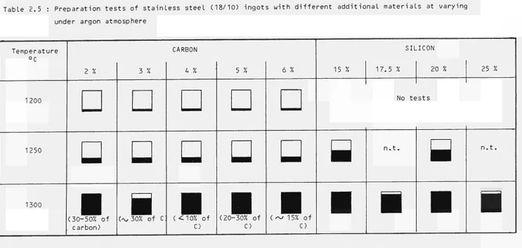
Tests have been performed on lowering the fusion points of zircaloy and stainless steel. Different mixtures, each of 200 grams, were maintained for four hours at the selected temperature in argon atmosphere.
Two utectics were considered for zircaloy alloys : (a) 78,5 w/o Zr - 21.5 w/o Cu at 995 PC ;
(b) 83 w/o Zr - 17 w/o Ni at 960 °C.
The fusion tests at 1200 °C on these utectics gave well melted ingots, whose metallographic examinations are under way. Carbon and Silicon were considered as ad-ditional material to stainless steel. The results, which are summarized in table 2.5, indicate 1300 ÇC as the lowest temperature to obtain a complete ingot. 2.4.1.2. Corrosion of Refractory Materials
The ceramics selected for the corrosion study and their composition in weight per cent (values in brackets) are
(+) ALCOR-B : AL 0 (99.3) (+) ISOSTAL-G : AL O (97 %) (+) ALUMINE (ISOSTATIC)
— 14
(* (*
(* (* (* (* (* ( ( + ( + (+ ( +
: MgO (96); CaO (2.5); SiO (1); F e203 (0.5)
: MgO (55); Cr O (20); A I O (8); F e203 (12)
MAGNORITE MN 197:MgO (97); SiO (1.5); CaO (1.3) ANKER-DI
ELECTREX-F55
C R203 - 1215 ZFE
SUPERSTAR GRAPHITE-ATJ MAGMALOX
C-104
CR-100
CSi CaF„
C r203 (96); Ti02 (3.6); F e ^ (0.3) ZrO + HfO (97); CaO (3)
C (25-30); CSi (20-25)
Al O (72); SiO (20); ZrO (5); >Na20J(0.8)
MgO (58); Cr O (28); Fe O (7); A 1203 (5); SÏ02 (1.3); CaOJ(0.7)
Cr O. (94); TiO„ (4.2); Al O (0.4); Mg
Mo.
4)"; Si02"(0.3) 2 32.4.2, Technological Study_
2.4.2.1. Prototype Fusion Rig
A simplified prototype rig for preliminary coating experiment at half-industrial scale with simulated claddings, was assembled (Fig. 2.4.1). It consists of a stainless steel box equipped to operate in ar-gon atmosphere and of a tilting electric induction furnace (fig. 2.4.2) with a crucible of 50 kg capa-city.
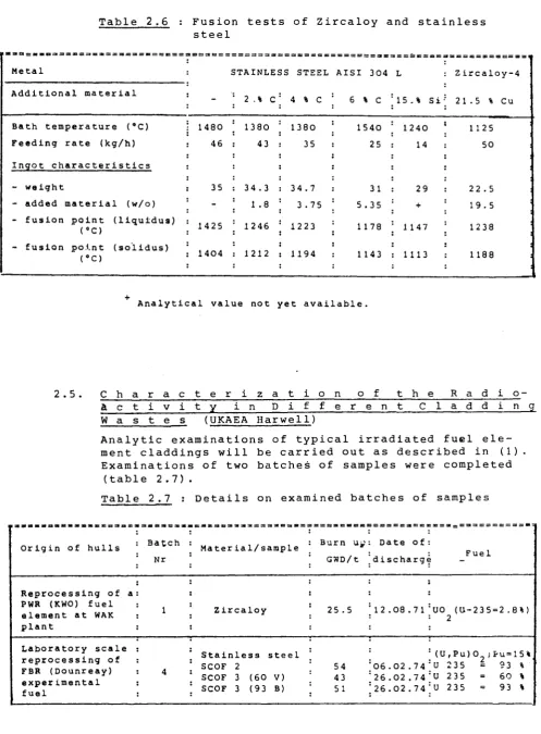
2.4.2.2, Compaction Tests by Fusion
Melting tests in argon atmosphere were carried out on following simulated wastes :
- Zircaloy 4 tubes length = 20-30 mm diameter = 8.25 mm
wall thickness = 0.5 mm - Stainless steel AISI 304 L length = 20-30 mm
diameter = 5 mm
wall thickness <= 0.5 mm After fusion of a small part of the material (3 k g ) , the furnace is fed at a rate depending on the diges-tion capability of the bath. The main data related to these tests are given in table 2,6.
Table 2.5 : Preparation tests of stainless steel (18/10) ingots with different additional materials at varying
under argon atmosphere
Temperature °C
1200
1250
1300
2 %
D
□
■
(30-50% ofcarbon)
3 %
D
□
■
(^30% of c:CARBON
4 %
D
□
■
(<10% ofC)
5 %
D
U
■
(20-30% ofC)
6 %
D
□
■
(~ 15% ofC)
15 %
Β
■
SILICON
17.5 % 20 %
No tests
n.t.
■
Β
■
25 %
n.t.
■
Total material for each sample = 200 g; dark surface represents the percentage of material forming the ingot;in brackets the amount of additions not incorporated in the ingot.
[image:27.842.23.766.102.455.2]16
T a b l e 2.6 : F u s i o n t e s t s of Z i r c a l o y and s t a i n l e s s steel
= => = = = = 0 3 = = = = = :
Metal
Additional material
STAINLESS STEEL AISI 304 L
2 .% C 4 % C 6 % C 15.% Si
Ζ ircaloy4
21.5 % Cu
Bath temperature ('C)
Feeding rate (kg/h)
Ingot characteristics
weight
added material (w/o)
fusion point (liquidus)
ra
fusion point (so'lidus) (gC)
1480 46 35 1425 1404 1380 43 34.3 1 .8 1246 1212 1380 35 34.7 3.75 1223 1194 1540 25 31 5,35 1178 1143 1240 14 29 + 1147 1113 1125 50 22 .5 19.5 1238 1188 2 .5
Analytical value not yet available.
C h a r a c t e r i z a t i o n o f t h e
a c t i v i t y ι η D i f f e r e n t C l a d d i
R a d i o
n_g_ W a s t e s (UKAEA H a r w e l l )
A n a l y t i c e x a m i n a t i o n s of t y p i c a l i r r a d i a t e d fuel e l e m e n t c l a d d i n g s w i l l be c a r r i e d o u t as d e s c r i b e d in ( 1 ) . E x a m i n a t i o n s of two b a t c h e s of s a m p l e s w e r e c o m p l e t e d
(table 2 . 7 ) .
T a b l e 2.7 : D e t a i l s on e x a m i n e d b a t c h e s of s a m p l e s
Origin of hulls
Reprocessing of a PWR (KWO) fuel element at WAK plant
Laboratory scale reprocessing of FBR (Dounreay) experimental fuel Batch Nr 1 4 Material/sample Zircaloy
Stainless steel SCOF 2
SCOF 3 (60 V) SCOF 3 (93 B)
! 3 = 3 5 3 * s m » S X Burn \i¿
GWD/t
25.5
54 43 51
Date of:
A · V. : F Ue l
discharge
12.08.71:UO (U235=2.8%)
: 2
:( U , P u ) 0 ;Pu=15%
[image:28.595.63.561.76.752.2] [image:28.595.64.557.88.340.2]— 17 —
Hulls were sectioned to provide rings of material which were subjected, directly or after complete dis-solution, to the experimental methods.
A detailed description of these methods is given in the literature (2; 3 ) .
2.5.1.- Total Content of Actinides
The Pu-239 contents of the hulls were determined (ta-ble 2.8) by three different methods :
- Neutron activation
After irradiation of the samples in a thermal neu-tron flux for about 1 min and cooling for 30 sees, the delayed neutrons emitted by fission are coun-ted. The method does not differentiate between different fissile nuclides.
- Direct alpha spectrometry
The content of the main alpha emitter will be evaluated by means of alpha-spectra taken from hull sections themselves.
- Alpha spectrometry of hull solutions
Actinides were determined by alpha-spectrometry on thin sources prepared from hulls solutions. The Pu-238 and Am-241 activities were measured after
separation of Pu (organic phase) from Am ( ,aqueous phase) by 10 % Tri-n-octylamine in xilene.
Table 2.8 : Pu-239 content of hulls (^Jg 239 Pu/g hulls)
METHOD Neutron
activation
Direct alpha- Alpha-spectro-metry on spectrometry^») 'sample solution
! iix
Batch Nr 1 (KWO)S i r c a l o y (4 s a m p l e s )
(6 s a m p l e s ) 1.4 - 5 . 2 2 - 5 . 6 16 .7
a t c h Nr 4 ( D o u n r e a y ) t a i n l e s s s t e e l - SCOF 2
t a i n l e s s s t e e l - SCOF 3 (60 V)
tainless steel - SCOF 3 (93 V)
200 - 570
mean of 10, : 370 55 - 550
mean of 10 : 173
44 - 200 mean of 10
54
18
23 119
457 - 919 mean of 4 : 773
18 - 63 mean of 2 1 : 47
43 - 69 mean of 5 : 53
18 —
2.5.2. Total_content_of_Activation_and_Fission Products The main gamma emitters were determined in complete· ly dissolved hull sections by gamma spectrometry. The results are given in table 2.9.
Table 2.9 : Activation and fission products in :
A Z i r c a l o y cladcjinq of batch " r 1 (.uCi/g tul Ls)
Sample (cooling time
Nr.3(2245 d) Nr.6( v/ 6 y) Nr.18(2245d> Nr.3 (*)
Mn54 1.82 2.0 234 Co58 500 Co60 183 12800 87 406 Zr95 4.3 4.5 1x10 Ru106 234 700 146 1.5x10^ Sb125 183 1300 398 828 Cs134 84 106 670 Cs137 382 100 463 432 Ce144 30 33 6.7x10 Eu152 Eu154
Β Stainless steel cladding of batch Nr 4 (mCi/g hulls) SCOF 2
<737d) SC0Fi<*)
SCOF 3 (GOV) (597 d) SCOF 3 (GOV) (*)
SCOF 3 (93V) (597V11 d)
8.6 44.2 8.1 30.5 7.9 0.59 803 1.0 345 1.0 0.57 0.74 0.35 0.43 0.33 0.89 3.57 0.09 0.15 0.06 0.44 0.46 0.25 0.26 0.10. 0.43 2.58 0.22 0.94 0.09 0.09 0.10 0.08 0.09 0.09 0.07 0.08 0.06 0.07 0.06
* Values corrected t o time of discharge from reactor
2 . 5 . 3 . S u r f a c e _ D i s t r i b u t i o n _ o f _ A l g h a
E m i t t e r s bv A l p h a
5 E 5 E ï E 2 ? ? ? £ £ ï _ ?
n dA u t o r a d i o g r a p h y
The r e s u l t s of a l p h a s p e c t r o r a e t r i c d e t e r m i n a t i o n
a r e
g i v e n i n T a b l e s 2 . 1 0 and 2 . 1 1 .
[image:30.595.55.548.246.589.2]— 19 —
immune to beta and gamma radiation, was placed in
intimate contact with the hull surface. Latent tracks formed by alpha particle can be developed in an etching solution ( F i g . 2 . 5 . 1 ) .
2 Table 2.10 : Surface activity of KWO hulls (mCi/m )
Sample Surface
Batch Nr 1
2 - Inner
2 - Outer
3 - Inner
3 - Outer
11- Inner
11- Outer
18- Inner
P u 2 3 9 + P u 2 4 0
(5.15 MeV) 1 .5 0.05 2.4 0.33 0. 74 O. 26 0.96
Pu2 3 8+Am2 41
(5.5 MeV) 2 .0
o.oy
3.6 0. 17 1 .73 0.272 . 1
Cm 244 (5.8 MeV) 0.94 0.02 1 .3 0.06 0.92 0.03 0.98 'Cm (6. 1 0 . 5 χ 1 χ 5 χ 9 χ 1 χ 3 χ 242 MeV) ' 01
io"
4io"
3io"
4io"
3io"
4io"
3 Date of measurement 14.02.77 ;09.02.77 [
15.02.77
19.02.77 ;
21.02.77
02.03.77 ;
06.03.77
Table 2.11 Surface activity.of stainless steel hulls
(Pu-239 atoms/cm )
Surface Batch sample Nr 4
SCOF 1 SCOF 2 SCOF 3 (60 V) SCOF 3 (93 V)
Inner
Outer
3.7 χ 10 16 8.3 χ 10
7.2 χ 10 15
16
2.1 χ 10 15 6.9 χ 10 15
1.2 χ 10 16 1.0 χ 10' 16
N.B : By uniform contamination of both surfaces at the level of 1 χ 10 atoms 239 Pu/cm , one tonne of hulls would contain 27 g of 239 P u .
2.5.4. Depth_Distribution_of Alpha Emitters_by_Alpha Spectrometry
— 20 —
2.5.5. Distribution of Fissile Nuclides by Fission Track Autoradiography
A film of a suitable detector material (e.g. Lexan poly carbonate) is placed in close contact with the surface of the sample, which is mounted in bakelite. After
irradiation in a thermal neutron flux {-„-2 χ 10 n/cm /sec) , the film is chemically treated to have preferential
etching in the regions damaged by fission particles. The tracks can be now observed under optical microsco pe or with a Quantimet Image Analysing system. A typi
cal example of the distribution of fissile material in Zircaloy hulls is given in- Fig. 2.5.3.
Stainless steel hulls were much more heavily contami nated on the outer radius than on the inside but, after cleaning the distribution was reversed (most of outside contamination was removed). Zircaloy hulls were much more contaminated on the inside and the distribution pattern was not changed on cleaning.
2.5.6. Remoyal_of_Actinides from Hull Surfaces
Table 2.12 gives results for different reagents used to clean stainless steel and Zircaloy samples in a ultraso nic bath.
Table 2.12 Removal of actinides from hulls (1 h agita tion in ultrasonic bath)
: Sample
'Stainless steel :SC0F 2
:SC0F 3 (60 V) :SC0F 3 (60 V) :SC0F 3 (93 V)
:SC0F 2
:SC0F 3 (60 V) :SC0F 3 (93 V)
'Zircaloy
:Hull m (Batch :Nr 1)
II II
Reagent/Temperature
3M HNO , 22eC
3Μ.ΗΝ0Γ. 22eC
6M HNO3 22°C
3M HNO,,* 22°C
3 60°C
3M HNO + 0.5 M HF, 22°C 3M HNO + 0.5 M HF, 22°C 3M HNO3 + 0.5 M HF, 22°C
3M HNO , 22eC
3Μ HNO + 0.5 M HF, 22°C 0.4 M Ammonium oxalate + 0.16 M Citric acid +
0.05 M H O , 22°C
Pu-:
removed
915 - 452 20.4- 35.4 34 68.2- 62.O 41 .6 902 38.1 65 .2
4 . 1
8 .6
3 .3
39 (fJg/q hui:
left
2.5 - 4.1 1.7 - 9.4
4.0 1.3 - 1.2
1 .3 <0.25
<0.2 5 <0.2 5
5 .4
8 . 1
6.9
.s) : Percentage
removed
: 99 : 9 2 - 7 9 : : 90 : : 98 :. ! 97 :
^»100 : rv»100 : rvJIOO :
: 43 :
: 52 :
— 21 —
Contami may be Using a the sta
to 0.2
reduce for 3M removal at 600 nation
nation of both type of hulls reduc
more inles 5/¿g
3M HNO at 22°C;
ed to the l10yt\g Pu239/g hulls range.
aggressive reagent (3M HNO + 0.5 M HF)
s steel contamination may be reduced the Ζ
HNO . of Ζ
Pu239/g hulls. This reagent did not ircaloy contamination below that found
American work (4) has shown that the
rO (e.g. by treatment with gaseous HF
s necessary to allow a good decontami °C) i
of Zircaloy hulls.
2.6 s m e η t t h e V a r i o u
τ
Υ Ρ
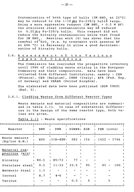
C l a d d i n gThe Commission has concluded the prospective inventory until 1990 of cladding waste arising in the European
Community and their composition. Data have been
collected from different Institutions, namely : CEA (France), CEN (Belgium), CNEN (Italy), KFK (Fed. Rep. of Germany) and UKAEA (United K i n g d o m ) .
The elaborated data have been published (Ref. 5) .
(EUR 5969)
2.6.1. Claddinçj_Wastes_f rom Different_Reactor_Types
Waste amounts and material compositions are summari
zed in table 2.13. In case of substantial differen
ces in the design of the same reactor type, both va lues are given.
Table 2.13 : Waste specifications
: Reactor :
Waste amounts (Kg/ton H.M.)
: Material com : position (w/o) j Zircaloy
Stainless steel : Harmonic steel
Inconel : Various
BWR :
400
80.5 9.5 1.3 8.7
PWR :
3 18rr4iO
8572 1 122
; 46
SGHWR:
282
77 22 .5
: 0.5
AGR
154
95
: 5
FBR (core) :
1422 1746 :
95 100 [
: 5 :
2.6.2. Waste_Arisings in_the_Community
[image:33.595.53.526.25.700.2]22
Table 2.14 Cumulative arisings of wastes (metric tons).
Country (fuel origin)
France : (LWR)
( Γ 13 Κ )
: total United Kingdom : (AGR) : (SGHWR) : (LWR) : (FBR) total Fed.Rep.of : Germany : (LWR)
! I t a l* (LWR)
: (FBR) total
! B e l9i u m ( LW R )
European Comm. (LWR) (AGR) (SGHWR) (FBR) : total 1980 :
4 1 5 ;
415 : 13 13 75 -. 490 13 : 503 1985 : 1740 1740 : 154 34 188 135 3 3 75 ; 1950 ! 1 5 4
: 38
1990 : 4529 - -375 4904 : 460 : 320 : 460 : 55 : 1295 480 : 250 : 10 : 260
: 430 :
6140 460 320 440
: 2141 : 7360 :
These amounts may become substantially lower, as a consequence of further delays in construction and commissioning of new reprocessing plants.
2.6.3. Radioactivity and Decay Heat
— 23
Table 2.15 Activation (A : KCi/te alloy) and
heat generation (H : W/te alloy) at different cooling times.
AL toy
Zircaloy4 Stainless steel (AISI 321) Inconel 718 Inconel χ 750
1 A
11
437
521
271
y H
77
2300
4130 2610
3 A
2.1
274
170
149
y H
27
1601
1430 1370
■
10 A 0.74
59
73
79
y H
11
572
547
543
25 y
A H
< 0.1
9.9
33
43
< 2
75
78
80
10C A
3.1
17
23
» y H
0.5
3
— 24
. Q
iî lOO 80 60 iO 20
ι
JS s* j f
ι
s AISI 30( " ZIRCALOY-ί
^ . - S ^ ^ " " "
, 1 1 1 , ».
10 20 30
COMPACTION PRESSURE (kg.mm'2)
FI,. 2.2.1 : «/„ΤΗ DENSITY Vs. COMPACTION PRESSURE
25 —
Fig. 2.2.3 : Compacted zircaloy-4 chops (74 % TH) encapsulated by Pb - 1.5 Sb alloy (vacuum casting at 723°K)
® = Container of unconditioned cladding waste
(§)= Feeding hopper
© = Vibrating runner to separate structural pieces
(o)= Conveying hopper
(§)= Rolling cylinders
(F) = FI u id co ncrete feed i ng
(G)= Conditioned waste drum
(H)= Dosing gear
to en
27 —
0 , 4 0
ro
Ό Χ
ω
+J
<υ
ί-U C Ο υ
σι
Ε Ο
α> ω ro
αϊ
Ι CM
re
0 , 3 5
0 , 3 0
0 , 2 5
0 , 2 0 ·
0 , 1 5
0 , 1 0 ■
0 , 0 5
w
ΡΖ450 F + 1 % Addiment
Δ
ΡΖ450 F + 1 % Tricosal
^.
ΡΖ450 F
D
ΡΖ350
ΕΡΖ350
Blitzdämmer
300
400
[°C]
FIG. 2.3.2 : HYDROGEN RELEASE FROM VARIOUS CONCRETE MIXTURES
0 . 0 3
0 . 0 2 "
οι 0 . 0 1
c o
~ 0 . 0 0 5 ■
'no 0 . 0 0 3
3 0 . 0 0 2
E
0.001
(Days)
10 20
ι
30
ι 40 ι
Α : 55°C
/ > / ,
Λ
Λ
Λ
Λ
Λ
y>
sï
O 7 . 8 % Zirconium
χ 7 . 3 % Zirconium
r
200
ι ι
400 600
Duration of test (h)
800 1000
30
20
™3 10 .
10
(Days)
20 30
B : 100°C
40
to oo
O
Χ
• · ι ι
200 400 600 800
Duration of test (h)
[image:40.842.52.803.56.497.2]1000
— 29
Argon out Let
i n Let
30 —
crucible U^^OO 0 2 . 5 0
\ capacity : 50 Kg of metaL
r e f r a c t o r y powder Lining
må o
Z_
cs>· . « S " . » · « · ' · ■ ¿ j *~ —■
ν ^ ^ ^ Λ
induction heating
/ refractory bLock (bricks)
concrete
31
:*.
kgv<SS*-íj·.·
i: >¡ !■
iát
·■ ■■«, s ..■■sf^l?^^ ■"■':·/^
— 32 —
4
E
8 7 6 5 4 3 2 1 — — D e p t h >im 5 1 MeV
Surface
OUIH >U)I'*C'
^ :
8 6 4 2 — D e p t h μπ>
O (Surface) 5.1 MeV
StainLess steeL huLLs SCOF 2 Specimen from batch sampLe Nr 4
« O M
•ACCO
12000
20000 leooo
Intensity U U b l U U T «fljJäS
» 0 0 0
12000
10000
3000 O
a
.«ÏJtoC^i^Kyso»>r^wv»m2W^
J O -J
TOOO « 0 0 0
« 0 0 Xfttaaalty O u b l t i u , n i t . )
4000 sooo 2000 ■000
OUTE« SUtFACF.
i
■
.··
..
•
'i .·
é » i O -J
ZircaLoy huLLs specimen Nr 3 from batch sampLe Nr 1
— 33
Mount
Outer surface
Zircaloy matrix
Inner surface
Mount
34 —
R E F E R E N C E S
(1) Commission of the European Communities : The Communities R & D Programme "Radioac
tive waste management and storage", First Annual Progress Report EUR 5749 (1977).
(2) A.D. Marwick - AERE R 8606 - "The distribution of plutonium on spent fuel element.
(3) J.L. Jenkins and M.J. Waterman AERE R 8608 -"The distribution of «(. and ν emitters in Proto type Fast Reactor stainless steel hulls".
(4) R.L. Dillon, Paper 16 in the IAEA/ΝΕΑ Technical Seminar on the treatment conditioning and stora ge of solid alpha-bearing waste and cladding hulls - Paris, December 5-7, 1977.
— 35 —
IMMOBILIZATION OF FISSION PRODUCT CALCES
A METALLIC MATRIX
— 36 —
TREATMENT OF Pu-CONTAMINATED COMBUSTIBLE
WASTES
4.1. G e n e r a l A s p e c t s a n d T e n d e
n-Plutonium contaminated wastes or more generally °< -wastes mainly arise from such operations at the back end of the fuel cycle as the extraction cycles of reprocessing, the reconversion of re-cycled fuel and the manufacture of MOX fuel ele-ments. A substantial part of this Pu-contamina-ted waste is combustible e.g. the gloves from glove-boxes, used filters, packing material and protective clothing.
The Community programme promotes five incineration studies and one specific investigation on Pu
recovery.
The broad aim of these projects is to : - reduce the volume of waste;
- obtain waste products, which are compatible
with available conditioning and disposal methods; - separate the actinides from other residues;
- recover plutonium where practicable.
During 1977, most of the new actions were placed with studies totally or largely devoted to the recovery of Pu.
Among the most difficult problems encountered by all investigators was to ensure satisfactory off-gas cleaning. Other problems not yet solved in many cases concern the construction materials and the process control.
4.2. H i g h T e m p e r a t u r e I n c i n e r a -t i o n (CEN/SCK-B)
4.2.1. Obj ectives
The objective of this contract is to develop the high temperature incineration technique for the treatment of plutonium (Pu) contaminated waste. Two aims are being pursued :
sui-— 37
table for long term storage and ultimate dispo sal by means of a modified commercial waste in cinerator (FLK60, capacity 100-150 kg/h),
(Ref. 1) ;
b) Incineration of heavily Pu-contaminated waste, with the aim to produce a readily soluble
product in order to promote maximum Pu-reco-very by means of a reduced scale pilot plant in development (capacity 10 kg/h).
4.2.2. Design and Construction Work
4.2.2.1. Installation and Testing of the Off-Gas Puri
fication System
The "installation of the off-gas purification system to the FLK60 plant was completed consisting of : - 2 heat exchangers;
- 2 panel bed filters; - scrubber unit;
- 2 absolute filters; - gas control system; - ventilation system; - stack.
The system has been tes le and repeatedly modif bed filters, whose rete to be insufficient, the torily performed. But ve yet been treated. Ρ
ficiency of the scrubbe HCL have been carried o HCL. 95 % of the HCL c believed that this can by adding Na OH. Exten bution measurements of out in situ. A safety system is in preparatio
ted in parts and as a who-ied. Apart from the panel ntion capacity was found
off-gas system satisfac-neither PVC nor rubber ha-reliminary tests on the ef-r unit foef-r tef-rapping gaseous ut by injection of pure
ould be trapped and it is be -substantially improved
sive particle size distri-fly ashes are 'being carried report for the off-gas
η .
4.2.2.2. Optimization of the FLK60 Plant and its Adapta tion for Pu-Contaminated Waste (Fig. 4.2.1)
38
The FLK60 plant has started operation with traces of A , / -activity in January 1978
Ó
4.2.2.3. Design and Construction of the Alpha Contain-ment and the Waste Pre-TreatContain-ment Facilities A layout of the alpha containment is given in Fig. 4.2.2.
During 1977 parts of the waste pre-treatment equipment have been constructed and tested. The design for the alpha containment was comple-ted and construction work will start 1978.
4.2.2.4. Installation of an Active Granules Charac-terization Laboratory
Parallel to the inactive laboratory an active one is being installed to handle medium active material. The following test equipment for the granules characterization will be included : - equipment for manufacture and preparation of
samples ;
- instrument for melting point measurements; - a furnace to simulate the melting process; - a furnace to produce ash samples;
- a leaching device for Pu-extraction tests. 4.2.2.5. Design of the Pilot Plant (Fig. 4.2.3.)
The general design of the pilot plant is comple-ted and a tender has been sent out for the cons-truction of the plant during 1978. A criticali-ly study is being carried out.
4.2.3. Experimental Work
— 39 —
4.2.3.2. Leaching Tests
The incremental leaching rate has been determi-ned according to IAEA specifications (Ref. 2) of the ash granules from various experiments. The average leaching rates for Fe , Cr and Co are given in table 4.2.3.
4.2.3.3. Structural Tests
The compositions of the original waste and the respective incineration ash investigated are given in tables 4.2.4 and 4.2.5. The reaction melting temperature of the mixture was lying between 1400 °C and 1460 °C. The melting point of the granules was 1360 °C + 10 °C. The resi-dual carbon content was decreased from 0,42 %
to 0,05 %. The "air" density of the obtained . granules was - 3,4 g/cm , "tap" density ^ 1,7 g/cm' Microprobe analysis yielded to the conclusions : - that the iron present is alloyed to all the
other components (especially to Cr) except to NiS;
- that sulphur is found in the BaSO matrix and in concentrated form in the Ni-phase.
Some scanning electron microscopes have been made showing in one case a pronounced glassy phase. A statistical analysis of granules respectively reacted and non-reacted materials is given in table 4.2.6.
4.2.3.4. Laboratory Experiments
Laboratory tests have been carried out to stu-dy the influence of waste components on the melting point of the granules, the volatility of some elements during the incineration and melting process and the solubility of some com-ponents on the final granules. The volatile components of ash granules was measured and amounted in some cases up to 4,5 % at 850 °C . Samples of simulated waste constituents and compositions were investigated. Incineration -and - melting point measurements with a
hot-stage microscope showed the following relations : - The incineration point of the green waste
increa-— 40 increa-—
ses with the increase of Fe content and de-creases with the increase of SiO and CaO contents.
Cylindrical pellets traces with Ru and C
have been heated in a pre-heated oven at 14ÕO °C for 15 minutes. The rate of volatility has been determined by the loss of the two isotopes coun-ting the remaining activity. Hence the volati-lity behaviour has been investigated in relation to the concentration of certain constituents, of which the following tendencies have been observed :
- decrease of C volatility with an increase of SiO + Fe o concentration as well as with an increase of acid components;
- maximum C volatility at /^45 % of alkaline content (decreasing above and below 45 % ) ; - maximum Ru volatility at <~<40 % of SiO + Feo0
concentration (decreasing above and below 4
2
- "
:
n>;
- minimum Ru volatility at/O35 % of alkalinecontent (increasing above and below 35 % ) . 137
Samples doped with C have been leached ac-cording to the specifications mentioned in chap-ter 4.2.2.1, the results of which are plotted in Fig. 424.
4.2.3.5. Study of Waste Compositions and Additives with the Aim of Highly Soluble Incineration Ashes
Investigations have been carried out on waste compositions and additives. The composition defined as the most waste mixture to start the pilot plant experiments with, in accordance with the experience gained from the FLK 60 operation, is given in table 4.2.7. A
statis-tical composition of the expected ash product is given in table 4.2.8. During the first tests plutonium will be substituted by cerium. According to a literature survey a mixture of Na CO -Na SO -NaCL as additives seems to be
2 ^ 3 2 . 4 most promising.
— 41 —
4.2.4. Interim Conclusions
The experimental operation of has demonstrated that, after and apart from the failure of filters, trouble free inciner tures up to 1500 °C can be ca leaching results on Cr indi good retention of the radioac The laboratory techniques for characterization of granules use under Pu-containing condi actions of the programme are behind the original schedule.
the FLK 60 plant some modifications
the panel bed ation at tempera-rried out. The cate a generally tive isotopes.
the simulation and are promising for tions. The main about one year
4.2.5. Planned Activities
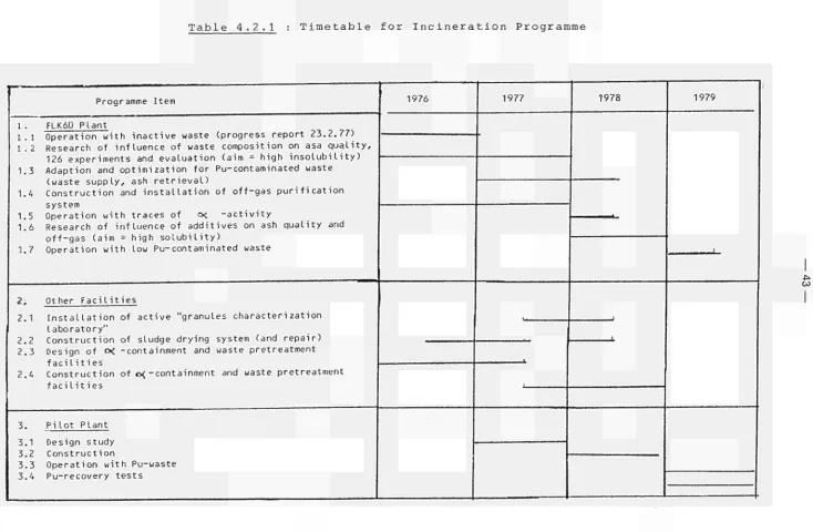
As indicated in the time schedule table 4.2.1, 1978 will be devoted to :
- the experimental operation of the FLK 60 -activity and in plant with traces of β , \/
conjunction; "
- the experimental research of the influence of additives on ash quality and off-gas (aim = high solubility);
- the completion of the active "granules charac terization laboratory";
- the repair of the sludge drying system;
- the construction of the alpha containment and the installation of the waste pre-treatment facilities and
- the construction of the pilot pilot plant (capacity 10 kg/h).
4.2.6. Complementary Action
42
prove the feasibility of the process and to optimize the process parameters - pressure, temperature, duration of compression and ob-tained densification - is carried out with a work-shop press during 1977/78 on inactive samples. The test samples will be examined with respect to leachability and microstruc-ture during 1978/79.
4.2.7. References
(1) First Annual Progress Report, contract EUR-017-76-7 WASB, N. Van de Voorde et. al (2) Atomic Energy Review, Vol
Table 4.2.1 : Timetable for Incineration Programme
Programme Item
1 . FLK60 Plant
1.1 Operation w i t h i n a c t i v e waste (progress report 23.2.77) 1.2 Research of i n f l u e n c e of waste composition on asa q u a l i t y ,
126 experiments and e v a l u a t i o n (aim = high i n s o l u b i l i t y ) 1.3 Adaption and o p t i m i z a t i o n f o r Pu-contaminated waste
(waste s u p p l y , ash r e t r i e v a l )
1.4 C o n s t r u c t i o n and i n s t a l l a t i o n of o f f - g a s p u r i f i c a t i o n system
1.5 Operation w i t h traces of o< - a c t i v i t y
1.6 Research of i n f l u e n c e of a d d i t i v e s on ash q u a l i t y and o f f - g a s (aim = high s o l u b i l i t y )
1.7 Operation w i t h low Pu-contaminated waste
2, Other F a c i l i t i e s
2.1 I n s t a l l a t i o n of a c t i v e "granules c h a r a c t e r i z a t i o n l a b o r a t o r y "
2.2 C o n s t r u c t i o n of sludge drying system (and r e p a i r ) 2.3 Design of c< -containment and waste pretreatment
f a c i l i t i e s
2.4 C o n s t r u c t i o n of o{ -containment and waste pretreatment f a c i l i t ies
3. P i l o t Plant
3.1 Design study 3.2 C o n s t r u c t i o n
3.3 Operation w i t h Pu-waste 3.4 Pu-recovery t e s t s
1976 1977
.
1978
■
1
1979
— ( t
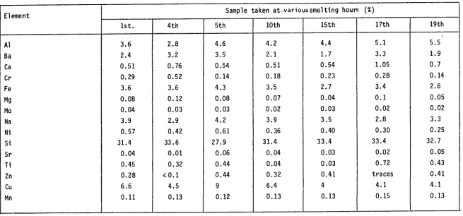
[image:55.842.71.805.35.515.2]Table 4.2.2 The composition of granules at various residence times in the reactor.
Element Al Ba Ca Cr Fe Mg Mo Na Ni Si Sr Ti Zn Cu Mn
Sample taken a t v a r i o u s s m e l t i n g hours (%)
1 s t .
3.6 2.4 0.51 0.29 3.6 0.08 0.04 3.9 0.57 31.4 0.04 0.45 0.28 6.6 0.11 4th 2.8 3.2 0.76 0.52 3.6 0.12 0.03 2.9 0.42 33.6 0.01 0.32 ¿ 0 . 1
4.5 0.13 5th 4.6 3.5 0.54 0.14 4.3 0.08 0.03 4.2 0.61 27.9 0.06 0.44 0.44 9 0.12 10th 4.2 2.1 0.51 0.18 3.5 0.07 0.02 3.9 0.36 31.4 0.04 0.04 0.32 6.4 0.13 15th 4.4 1.7 0.54 0.23 2.7 0.04 0.03 3.5 0.40 33.4 0.03 0.03 0.41 4 0.13 17th 5.1 3.3 1.05 0.28 3.4 0.1 0.02 2.8 0.30 33.4 0.02 0.72 t r a c e s
4 . 1 0.15
19th
[image:56.842.104.759.184.490.2]— 45
Table 4.2.3 Leaching factor after 236 days ■
Leaching in demineralised water
Sample
76/33/04
76/33/06
Isotope
C r
5 1F e
5 9C o
6 0C r
5 1F e
5 9C o
6 0-l, -1
g.cm.day
L χ D
3,09 χ IO'
1 04,35 χ IO"
1 11,62 χ IO"
1 01,40 χ IO"
1 04,34 χ IO'
1 18,52 χ IO'
9cm.day"
L
9,08.IO'
111,28.IO"
114,78.IO'
114,19.IO"
111,30.IO"
112,55.IO"
9L =
W L y i
>cnKday
i
4F
¿— 46
Table 4.2.4 Composition of artificial waste (code : US 2/5).
Components
Combustible :
paper
plastics (P.E.) ion exchangers
Metals Sand Glass Na2C03 Water Sludge(x)
Sludge composition : BaSO. : 43.29 4 Fe203 : 35.11 A1203 : 6.25
Si02 : 5.00
BaCO : 4.81 CuO : 2.88 MgO : 0.76
Mn02 : 0.76
Ca(0H)2 : 0.62
Ti02 : 0.48
%
28.3 14.3 + 9.5
52.1
9.5 6.7 1.9 1.9