1
University of Southern Queensland
Faculty of Engineering and Surveying
Evaluating the Differences and Accuracies Between
GNSS Applications Using PPP.
A dissertation submitted by
Mr. Wafeek Ismail
In fulfilment of the requirements of
Course ENG4111 and ENG4112 – Research Project
Towards the degree of
2
Abstract
Global Navigation Satellite Systems (GNSS) are satellite systems with global coverage. There are currently several GNSS systems in operation today including the United States NAVSTAR Global Positioning System, Russian GLONASS, Chinese Beidou and the European Union’s Galileo system. The Galileo and Beidou systems are currently undergoing upgrading in order to achieve more sustainable and comprehensive worldwide exposure, ultimately providing users with a broader option of systems and wider more reliable coverage.
In recent years, in addition to the GPS constellation, the ability to utilise extra satellites made available through the GLONASS and Beidou systems has enhanced the capabilities and possible applications of the precise point positioning (PPP) method. Precise Point Positioning has been used for the last decade as a cost-effective alternative to conventional DGPS-Differential GPS with an estimated precision adequate for many applications. PPP requires handling different types of errors using proper models. PPP precision varies with the use of observations from different satellite systems (GPS, GLONASS and mixed GPS/GLONASS/Beidou) and the duration of observations. However, the fundamental differences between GPS, GLONASS, Beidou and Galileo and the lack of a fully tested global tracking network of multi-Global Navigation Satellite Systems necessitate the evaluation of their combined use. More studies are required in order to confirm the reliability and accuracy of the results obtained by the various methods of PPP. This is outside the scope of this paper.
This research paper will evaluate and analyse the accuracy and reliability between different GNSS systems using the Precise Point Positioning technique with emphasis on the function and performance of single systems compared with combined GNSS systems. A methodology was designed to ensure accurate and reliable results have been achieved. Solutions generated from identical data will be compared for bias, accuracy and reliability between single standalone GPS and combined GNSS systems. This study focused on the performance of these systems over a twenty four hour observation period, decimated into 1, 2, 6, 12 and 24 hours. The study found that the reliability and performance of GNSS systems over standalone GPS was insignificant over a twenty four hour period. In fact, where satellite availability and constellation are at a premium, standalone GPS systems can produce equivalent quality results compared with combined GNSS. Having said this, the combined GNSS systems achieved quicker convergence times than
standalone systems.
With limited access and availability to resources, in particular GNSS receivers, the results can be seen as preliminary testing enhancing the knowledge of GNSS users. Nonetheless, this
3
LIMITATIONS OF USE
The Council of the University of Southern Queensland, its Faculty of Health, Engineering & Sciences, and the staff of the University of Southern Queensland, do not accept any
responsibility for the truth, accuracy or completeness of material contained within or associated with this dissertation.
Persons using all or any part of this material do so at their own risk, and not at the risk of the Council of the University of Southern Queensland, its Faculty of Health, Engineering & Sciences or the staff of the University of Southern Queensland.
This dissertation reports an educational exercise and has no purpose or validity beyond this exercise. The sole purpose of the course pair entitled “Research Project” is to contribute to the overall education within the student’s chosen degree program. This document, the associated hardware, software, drawings, and other material set out in the associated appendices should not be used for any other purpose: If they are so used, it is entirely at the risk of the user.
4
CANDIDATES CERTIFICATION
I certify that the ideas, designs and experimental work, results, analysis and conclusions set out in this dissertation are entirely my own effort, except where otherwise indicated and
acknowledged.
I further certify that the work is original and has not been previously submitted for assessment in other course or institution, except where specifically stated.
Wafeek Ismail
Student Number: W0086030
_______________________ (Signature)
5
ACKNOWLEDGEMENTS
This research was carried out under the supervision of Dr Zhenyu Zhang. I would like to thank Dr Zhang for his guidance and support throughout.
I would like to further thank Ultimate Positioning Group for providing me with the necessary equipment required to complete my field studies.
Finally a special thank you to my wife and family for all the support and patience shown
6
LIST OF FIGURES
Number
Title
Page
1.1 GPS Satellite Slot Constellation 20
1.2 GLONASS Satellite Constellation 21
1.3 Assignment of GLONASS Satellites In Each Plane 21
1.4 Galileo Space Segment 22
1.5 Galileo Navigational Signals 23
1.6 Chinese Beidou-2 Space Segment 24
1.7 United States GPS Control Segment 25 1.8 Location of GLONASS Control and Command Centres 26 1.9 Configuration of Galileo Space Segment 27 2.1 Two Dimensional Pseudorange Positioning 32 3.1 Aerial Photo of Cromer Heights Trig Station 37 3.2 Aerial Photo of Carrol Trig Station 37 3.3 Aerial Photo of Mccowen Trig Station 38
3.4 IGS Tracking Network 39
3.5 APREF CORS Network in Australia – Pacific 39 4.1 Plot of SCIMS Vs Combined GNSS Solutions 42
7
LIST OF TABLES
Number
Title
Page
Table 2.1 Multipath Mitigation by Correcting Raw Observations 30 Table 2.2 Multipath Mitigation by stochastically de-weighting observations 30
Table 4.1 GNSS AUSPOS solutions Vs TS 1421 SCIMS coordinates 43 Table 4.2 GNSS AUSPOS solutions Day 2 Vs TS 1421 SCIMS coordinates 44
Table 4.3 GNSS Day 1 Vs GNSS Day 2 44
Table 4.4 GPS AUSPOS solutions Vs TS 10447 SCIMS coordinates 47 Table 4.5 GPS AUSPOS solutions Day 2 Vs TS 10447 SCIMS coordinates 48
Table 4.6 Day 1 GPS Vs Day 2 GPS 48
8
LIST OF APPENDICES
Number
Title
Page
A Project Specification 65
B 24 Hour Solutions Combined GNSS (TS1421) 67 C 24 Hour Solutions Standalone GPS (TS10447) 68 D 12 Hour Solutions GNSS (TS3018) 70
E 12 Hour Solutions GPS (TS3018) 71
F SCIMS Survey Mark Reports 73
G RINEX File Example 77
9
NOMENCLATURE AND ACRONYMS
The following abbreviations have been used throughout the text and bibliography:-
AHD Australian Height Datum AHD71 Australian Height Datum 1971 APREF Asia Pacific Reference Frame
CORS Continually Operating Reference Station FDMA Frequency Division Multiple Access GCC Ground Control Centre
GCS Galileo Control System
GDA94 Geocentric Datum of Australia 1994 GEO Geostationary Earth Orbit
GRF Galileo Reference System
GLONASS Globalnaya navigatsionnaya sputnikovaya sistema (Global Navigation Satellite System)
GMS Galileo Mission System
GNSS Global Navigation Satellite System GPS Global Positioning System
ICSM Intergovernmental Committee on Surveying and Mapping IGS International GNSS Service
IGS08 International GNSS Service 2008 ISS International Space Station
ITRF International Terrestrial Reference Frame ITRF2008 International Reference Frame 2008 LPI Land and Property Information MCS Master Control Station
MEO Medium Earth Orbit PPP Precise Point Positioning QZSS Quasi Zenith Satellite System
RINEX Receiver Independent Exchange Format RNSS Regional Navigation Satellite Systems RTK Real Time Kinematic Surveying SBAS Space Based Augmentation System
SCIMS Survey Control Information Management System SP Standard Precision
SRNS Satellite Radio Navigation System SU Survey Uncertainty
10
TABLE OF CONTENTS
CONTENTS
Page
ABSTRACT………... 2
LIMITATIONS OF USE……….………... 3
CANDIDATES CERTIFICATE………... 4
ACKNOWLEDGEMENTS………... 5
LIST OF FIGURES……….………... 6
LIST OF TABLES………...………... 7
LIST OF APPENDICES……….………... 8
NOMENCLATURE AND ACRONYMS...………...9
Chapter 1 – Introduction………...
13
1.1.Project background………... 13
1.1.1. GNSS Background information………...13
1.1.2. Performance analysis GNSS systems using PPP………..15
1.1.3. Project Context………..16
1.2.Project Aims and Objectives………17
1.2.1. Project Aims………...17
1.2.2. Project Objectives………...17
1.3. Chapter Summary………...18
Chapter 2 – Literature Review………...
19
2.1. Introduction………... 19
2.2. Physical Application………... 19
2.3. The Control Perspective……… 25
2.4. The User Segment………. 28
2.5. Performance Analysis GNSS Systems Using PPP………... 28
2.6. Quality of AUSPOS Online PPP Software Coordinates………... 31
2.7. Differential GNSS………...31
2.8. Chapter Summary………...32
Chapter 3 – Methodology………...
34
3.1. Introduction………...34
11
3.2.1 Equipment………... 35
3.2.2 Field Method……….. 35
3.2.3 Survey Trig Station Sites………...36
3.3. Data Processing………..………...38
3.3.1 Raw Data………38
3.3.2 Processed Data………..38
3.3.3 Online PPP Post Processing Services – AUSPOS………...38
3.3.4 Data Comparisons……….. 40
3.4. Chapter Summary………..……… 40
Chapter 4 – Results………...
41
4.1. Introduction………..41
4.2. Processed Solutions………..………. 41
4.3. Twenty Four Hour GNSS Observation Results (TS1421)………..………. 41
4.3.1 Carrol Trig Station 24 hour combined GNSS observation solutions.………42
4.3.2 GNSS Vs TS1421……… 43
4.3.3 GNSS Day 2 Vs TS1421………..44
4.3.4 GNSS Day 1 Vs GNSS Day 2 Solutions……….44
4.4. Twenty Four Hour GPS Observation Results (TS 10447)……… 46
4.4.1 Cromer Trig Station (TS10447) 24 Hour GPS Observation Solutions………...46
4.4.2 GPS Day 1 Vs TS10447………..47
4.4.3 GPS Day 2 Vs TS10447………..48
4.4.4 GPS Day 1 Vs GPS Day 2 Solutions………48
4.5. Twelve Hour GNSS Observation Results (TS 3018)………...49
4.5.1 GNSS Day 1 Vs TS3018..…………..………...49
4.5.2 GNSS Day 2 Vs TS3018………..50
4.5.3 GNSS Day 1 Vs GNSS Day 2 ………...50
4.6. Twelve Hour GPS Observation Results (TS 3018)………...51
4.6.1 GPS Day 1 Vs TS3018 ……….51
4.6.2 GPS Day 2 Vs TS3018 ……….52
4.6.3 GPS Day 1 Vs Day 2….……….52
4.7. Chapter Summary..………..………53
Chapter 5 – Data Analysis………...
54
5.1. Introduction………..54
5.2. Combined GNSS Solutions Analysis………..54
5.3. GPS Only Solutions Analysis………55
12
5.5. Combined GNSS & GPS Vs SCIMS……….56
5.5.1 SCIMS Vs Solutions Error……….……….56
5.6. Solution Bias………..……….57
5.7. Chapter Summary………..……….58
Chapter 6 – Conclusion……….
59
6.1. Introduction………..59
6.2. Recommendations………...59
6.3. Conclusion…………..………60
Chapter 7 – References……….
61
Appendices………
65
Appendix A Project Specification………65
Appendix B 24 Hour Solutions Combined GNSS (TS1421)……….67
Appendix C 24 Hour Solutions Standalone GPS (TS10447)……….. 68
Appendix D 12 Hour Solutions GNSS (TS3018)………. 70
Appendix E 12 Hour Solutions GPS (TS3018)………. 71
Appendix F SCIMS Survey Mark Reports……….. 73
Appendix G RINEX File Example………..77
Appendix H Trimble R10 GNSS Receiver Specifications………..78
13
Chapter 1 – Introduction
1.1
Project background
1.1.1
GNSS background information
Global Navigation Satellite Systems (GNSS) are satellite navigation systems with global coverage. There are several systems in operation today ranging from the United States
NAVSTAR Global Positioning System (GPS) to Russian GLONASS system. These two systems are currently fully operational. Whereas the Chinese Beidou-2, European Union’s Galileo and the Japanese Quasi-Zenith satellite positioning systems are currently in the expansion and
development stage due to be optimally operational by the year 2020.
GNSS are used to pinpoint the geographic location of a user’s receiver anywhere in the world (TechTarget, 2014). They use a system of triangulation to locate the user through calculations using a series of visible satellite. Each satellite transmits a coded signal at precise intervals.
The receiver converts signal information into position, velocity and time estimates (Trimble, 2014). Using the information transmitted, the receiver calculates the distances between it and the satellites which ultimately enable the receiver to determine its position.
Global Navigation Satellite Systems were initially created by the United States and Russian governments for military use. Since there initial inception however Global Navigation Satellite Systems have come a long way being used throughout various commercial, residential, construction, infrastructure as well as a host of other industries. Today the United States
NAVSTAR system, better known as Global Positioning System or GPS is commonly used within the automobile industries for navigational purposes, fleet tracking, mining and recreational use such as fishing and hunting. More importantly perhaps is GNSS use throughout the mapping and surveying industries. The surveying and mapping industry has been revolutionised by the use of GNSS, involving satellites, ground reference station infrastructure and user equipment to
determine positions around the world (Chris Rizos, 2005).
14
receiver to calculate its position was about 15 minutes (Reece, 2000). The current GPS is a vast improvement over the Transit system. The original use of GPS was as a military positioning, navigation, and weapons aiming system to replace not only Transit, but other navigation systems as well (Reece, 2000). It has higher accuracy and stable atomic clocks on board to achieve precise time transfer. The first GPS satellite was launched in 1978 and the first products for civilian consumers appeared in the mid 1980's (Reece, 2000). The GPS system was made available to the civil community in the year 1984 by than president Ronal Reagan. The system is consistently being improved and upgraded with new satellite replacing older outdated ones. The Russian GLONASS system was also formed in 1982 by the country’s military defence force and is currently operated by the Russian government. The system provides an alternative to the Global Positioning System and is the second alternative navigational system in operation with global coverage and of comparable precision. Toward the end of the 1960s the military identified a need for Satellite Radio Navigation System (SRNS) for use in precision guidance of the new generation of ballistic missiles. The existing Tsiklon satellite system that was available at the time could not be used for this purpose due to the lack of satellite availability, accuracies and the fact that the system required several minutes of observation time by the receiving station to obtain a fix on a position. Hence the introduction of navigation satellites with autonomous orbit corrections known as the Globalnaya Navigatsionnay Sputnikovaya Sistema (GLONASS) system was created.
In the early nineties the European Union saw the need for Europe to have its own global satellite navigation system. The European Commission and European Space Agency joined forces to build Galileo, an independent European system under civilian control (Agency, 2014). Although the system is currently set to be fully operational by the year 2020, the system still provides a highly accurate global positioning service under civilian control. It is inter-operable with GPS and GLONASS. Galileo receivers compute their position in the Galileo Reference System using satellite technology and based on triangulation principles (Agency, 2014). As mentioned, the United States GPS, Russian GLONASS and Chinese Beidou systems, although available for civil service are all militarily controlled systems, which means these systems may be switched off or made less precise when desired, usually during times of conflict. With the world becoming ever more dependent on services provided by satellite navigation within our daily lives, having these systems reduced or switched off has the potential to severely disrupt everyday activities and businesses such as business, banking, transport, aviation, communication etc. This is where having a system within civilian control has its advantages (Agency, 2014).
15
This system is known as the Chinese Beidou2 GNSS system, which is China’s second
generation satellite navigation system that will be capable of providing positioning, navigation, and timing services to users on a continuous worldwide basis (Agency, 2014). Although the plan in the year 1997 was to have the regional system evolve from a regional to global solution, the formal approval by the Government of the development and deployment of BDS System was done in 2006 and it is expected to provide global navigation services by 2020, similarly to that of GPS, GLONASS or Galileo systems (Agency, 2014). Further, in 2011 the Beidou system was announced to provide initial operational service providing initial passive positioning for the Asia-Pacific region having a constellation of ten satellites. The number of satellites were increased by a total of five additional satellites in 2012, where the number of satellites will continue to increase ultimately evolving towards global navigation capabilities by the year 2020 (Agency, 2014
).
1.1.2
Performance analysis GNSS systems using PPP
Precise Point Positioning is a satellite based positioning technique aiming at high accuracies in close to real time. The technique is capable of producing these high accuracies of centimetre to sub centimetre positioning using a single GNSS receiver, eliminating the constraints of base of baseline length and simultaneous observations at both rover and reference stations (Katrin Huber, 2010). It is a combination of the original absolute positioning concept and differential positioning techniques. PPP was developed based only on GPS observations, the accuracy, availability and reliability of positioning is dependent on the number of visible satellites at any given time. One way of ensuring an increase in availability of satellites is to integrate GPS and GLONASS observations. Today such integrations in Precise Point Positioning are available and will be discussed later on. The PPP technique is essential in single receiver observations in order to correct for the various errors that are inherent in raw observation data. These errors are
caused by such things as atmospheric composition, differences in satellite and receiver clock accuracies, differences in modelled and actual satellite position and orientation and geological effects.
16
not requiring dedicated reference stations it requires a long convergence time to achieve a desired accuracy (Pan Li, 2014). The precise point positioning technique combines precise clocks and orbits calculated from a global network. Pseudorange multipath and pseudorange noise are the largest remaining unmanaged error sources in PPP. It is believed that reducing the effects of multipath and noise on the pseudorange observable, accurate estimates of carrier phase float ambiguities will be attained sooner, ultimately reducing the initial convergence period of PPP (Garrett Seepersad, 2014). With the use of modernized GPS, Beidou, Galileo and
GLONASS there are several advantages to be gained such as the availability of more visible satellites, greater signal power levels and more potential observable combinations, which may result in improved positional accuracy, availability and reliability. Both the pseudorange multipath and noise represent the largest remaining unmanaged error source in PPP. The amplitude of the multipath-induced errors in carrier phase observations is limited to a quarter wavelength or about 5 cm, but is typically well below 2 cm. Pseudorange multipath can have a magnitude of up to 10– 20 m as it depends directly on the distance to the reflector. Currently, Hatch filtering is being performed in the position domain of the PPP software to mitigate pseudorange multipath and noise with minimal improvements in the rate of convergence (Garrett Seepersad 2014).
Pseudorange multipath and noise can be corrected using several different methods to ultimately reduce convergence times and increase accuracies.
1.1.3
Project Context
Documenting the effects and reliability as well as the differences and accuracies between the different GNSS systems using the Precise Point Positioning technique is of extreme importance particularly to the surveying industry. GNSS systems have come a long way since there initial inception in the mid to late 1900’s. These systems have revolutionized the surveying and construction industries in many ways allowing surveyors to obtain highly accurate positioning information for both as built and design information, as well as provide GPS based machine guidance systems which in turn provide accurate grading information to machine operators. This ultimately ensures tasks are completed much more efficiently and economically than
conventional surveying methods using an EDM, while maintaining the high accuracies required by both the surveyor and the client.
With the growing influence of these systems within the construction, civil, infrastructure, mining and more importantly the surveying industries, the demand for quality, efficiency and economic viability has increased dramatically. The industry has become more dependent on these systems and therefore it is imperative that surveyors gain greater understanding and awareness of Global Navigation Satellite Systems, there functionality and accuracies.
17
The paper will further focus on different physical and application details and specifications to evaluate them in terms of practical relevance. It is imperative that surveyors and other industry professionals understand and gain confidence of the mechanics, accuracies and configurations of systems they will use throughout their careers.
1.2
Project Aims and Objectives
1.2.1
Project Aims
Although GNSS are currently in in use and heavily relied upon within the surveying industry particularly surveying within the construction, infrastructure and civil sectors, the technical aspects of these systems including their performances within robust and diverse terrain are usually misunderstood. Surveyors will at some stage throughout there working careers work with GNSS systems and it is imperative that these systems are understood.
On this, the aim of the project is to provide relevant technical information on the performance of GNSS systems and their accuracies, both through single GNSS system and a combination of systems to test whether these combinations achieve quicker convergence, accuracy and reliability compared with the use of only a single system.
1.2.2
Project Objectives
The objectives of the study are to:
1. Gain understanding of systems by performing a literature review
2. A Performance analysis of GNSS systems using Precise Point Positioning (PPP) 3. Accuracy of stand-alone verse combined Global Navigation Satellite Systems 4. Research technical specifications for differences in GNSS systems
5. Research geographical differences of GNSS systems 6. Process data and analyse results
7. Compare post-processed solutions to known coordinates to evaluate accuracy and precision of solutions for twenty four hour logging times
8. Conclusion
With the Beidou and Galileo systems currently in the upgrading stage before they are fully functional and universally accessible, the performance analysis using the Precise Point
18
1.3
Chapter Summary
This project seeks to, by means of research, find aspects of design, physical limitations or advantages that will provide a level of differentiation between current stand along Global
19
Chapter 2 – Literature Review
2.1 Introduction
The United States government’s policies has evolved over time as the industry has moved from the GPS system being the only system to a broader international framework. The development of other systems such as the GLONASS, Galileo and Beidou has changed the dynamic into a multinational and multi system context (Madry, 2015). With the realisation that high precision services provided by both the United States GPS and Russian GLONASS may not be reliable during times of conflict with the systems being controlled by the country’s military services respectively, the need has arisen across much of the globe where a necessary alternative to these systems be created, hence the introduction of self-contained GNSS systems such as the European Union’s Galileo and Chinese Beidou systems. This issue has been further addressed, by the implementation of additional resources to GPS and GLONASS base receivers to form Space Based Augmentation Systems (SBAS) or Regional Navigation Satellite Systems (RNSS).
To assess the differences, accuracies and advantages or limitations between stand alone and combined between any two or more Global Navigation Satellite Systems we need to gain an understanding of the development of each system
.
2.2 Physical Application
Global Navigation Satellite Systems consist of three major components or segments. These segments are known as the space segment, control segment and user segment (Grush 2006). The space segment comprises the physical, orbiting components such as the satellites, space vehicles, constellations, clock signals structure radio etc.
20
[image:20.596.65.477.123.341.2]receiver and cannot penetrate water, soil, walls, or other obstacles such as trees, buildings, and bridges.
Figure 1.1 – Expandable 24-slot constellation, (National Coordination Office for Space
Based Positioning, 2015)
All signals transmitted by the satellite are derived from the fundamental frequency (f0) of the satellite oscillator. The two carrier frequencies used are f1 and f2 with corresponding wavelengths of nineteen and twenty four centimetres respectively (Positrim, 2012). The satellites initially transmitted Coarse/Acquisition (C/A) code signals modulated on the L1 carrier only at (1575.42MHz) band and the P-code (Precise or Protected) code on both the L1 and the L2 (1227.60MHz) bands (National Coordination Office for Space Based Positioning, 2015). Clock accuracy is one of the most important factors in achieving positioning accuracy, In a study by (T K Yeh, 2007), a 1–2 cm positioning error was found due to improperly modelled receiver clock errors (T K Yeh, 2007). In GPS positioning, receiver clock errors are considered systematic errors that can be reduced by differencing the GPS code and phase observables (Ta-Kang Yeh, 2009).
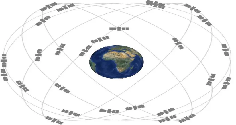
The Russian GLONASS system as mentioned previously was formed by the country’s military defence force and currently operated by the Russian government. This satellite system is currently fully operational consisting of twenty four operational satellites separated over three 120° orbital planes (Agency, 2014). Within each plane there are a total of eight satellites,
21
[image:21.596.73.522.101.329.2]from any position on the earth at any given time.
Figure 1.2 – GLONASS constellation (Agency, 2011c).
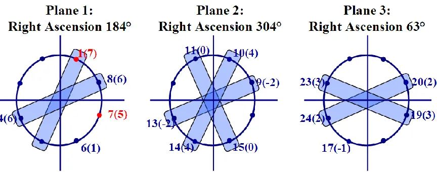
GLONASS system uses Frequency Division Multiple Access (FDMA) to transmit its ranging signals, in both the L1 and L2 bands. According to this scheme, each satellite transmits navigation signals on its own carrier frequency, so that two GLONASS satellites may transmit navigation signals on the same carrier frequency if they are located in antipodal slots of a single orbital plane (Rodríguez, 2011). Figure 2 below shows the satellites assigned to each of the GLONASS planes.
Figure 1.3 – Assignment of GLONASS satellites in each plane (Rodríguez, 2011).
[image:21.596.67.499.502.672.2]22
Galileo L1 bands. The L1 band ranges from 1602.5625 MHz to 1615.5MHz. The GLONASS satellites each transmit on slightly different L1 and L2 frequencies, with P- code on both L1 and L2, and with C/A code, at present, only on L1. GLONASS-M satellites reportedly transmit the C/A code on L2. The L2 frequencies run from 1240 MHz to 1260 MHz. Finally the L3 signal centres around the 1202.025 MHz. This L3 band was introduced to the GLONASS K-1 satellites in the year 2012.
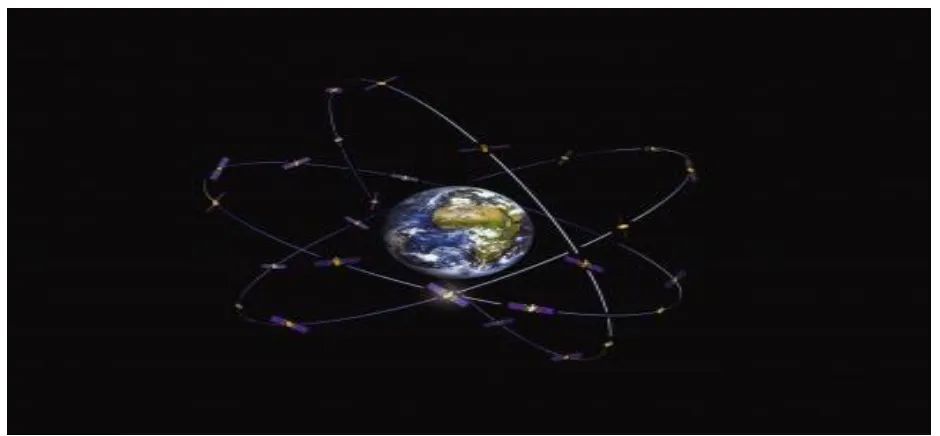
[image:22.596.57.527.454.672.2]The Galileo System is Europe’s navigational satellite system which provides high accuracies for global positioning. The system is interoperable with both the GPS and GLONASS navigational systems. The system’s receivers compute their positions in the Galileo Reference System (GRF) using satellite technology and based on the triangulation principles (Agency 2013). The main functions of the Galileo Space segment are to generate and transmit code and carrier phase signals and to store and retransmit the navigation message sent by the Control Segment. These transmissions are controlled by highly stable atomic clocks on board the satellites (Agency, 2014). The space segment when fully operational will consist of thirty satellites, 27 operational and 3 spares, in medium earth orbit at an altitude of approximately twenty three thousand kilometres across three orbital planes inclined at fifty six degrees to the equator, spread evenly around each plane taking approximately fourteen hours to orbit the earth (Agency, 2014). The combination of the orbital inclination and the flight altitude of the satellites will considerably increase the coverage of the Polar Regions (Cojocaru, 2009).
Figure 1.4 – Galileo Space Segment (Agency, 2014)
23
commercial (CS) and public regulated services (PRS). The open services signal uses L1, E5A, and E5B as well as combinations such as using L1 and E5a for best ionospheric error
cancellation. All satellites transmit signals at the same frequency, which are distinguished by receivers through the addition of a code to each signal. This code is different for each satellite and its design is one of many arts involved in making a good satellite navigation system (Agency, 2007).
[image:23.596.67.537.427.626.2]By using many signals this allows the receiver to estimate the ionospheric delay errors. This error occurs when the signal is delayed when travelling through the ionosphere, which in turn makes the distance from the satellite to the user appear longer than it actually is which will lead to large positional errors if not corrected. Lower frequency signals experience longer delays than signals with higher frequencies. Therefore, by combining measurements to the same satellite at two different frequencies it is possible to produce another measurement where the ionospheric delay error has been cancelled out (Agency, 2007). The shape of the spectrum of the signal is due to the modulation adopted for Galileo. This modulation has been chosen to avoid interference with other satellite navigation systems such as the United States GPS system on the L1 band. The Modulation adopted is called BOC (1,1), which means Binary Offset Carrier of rate (1,1) (Agency, 2007). By adopting this modulation this ultimately allows both the GPS and Galileo systems to use the same frequency while avoiding mutual interference.
Figure 1.5 – Each Galileo Satellite will broadcast 10 different navigation signals (Agency,
2007).
24
Earth Orbit (MEO) satellites (Office 2013). The GEO satellites operate in orbit at approximately thirty five kilometres and are positioned at 58.75°E, 80°E, 110.5°E, 140°E and 160°E
respectively. The IGSO satellites operate with an orbital altitude of approximately thirty six
kilometres and an inclination of fifty five degrees to the equatorial plane. Finally the Medium Earth Orbit satellites orbit at an altitude of twenty one kilometres and as with the IGSO satellites
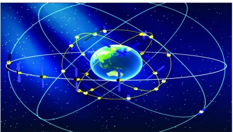
[image:24.596.61.523.255.517.2]operate at fifty five degrees to the equatorial plane. The satellite recursion period is thirteen rotations within seven days (Office 2013). Beidou’s current constellation of 5 geostationary, five inclined geosynchronous orbit and four middle earth orbiting spacecraft are transmitting open and authorised signals at B1 (1561.098 MHz) and B2 (1207.14 MHz) and an authorized service at B3 (1268.52 MHz) (Spirent, 2015). Figure 6 below shows Biedou-2 space augmentation.
Figure 1.6 – Chinese Beidou-2 Space Segment (Pace, 2010).
25
to be fully operational with worldwide coverage by the year 2020.
2.3
Control Perspective
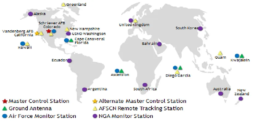
[image:25.596.63.482.253.450.2]The GPS control segments consist of a global network of ground facilities that track the GPS satellites, monitor their transmissions, perform analyses, and send commands and data to the constellation. The current operational control segment includes a master control station, an alternate master control station, 12 command and control antennas, and 16 monitoring sites (Parkinson 2013).
Figure 1.7 – United States GPS Control Segment (GPS.gov, 2015)
The master control station (MCS) located at the Schriever Air Force Base in Colorado is responsible for the overall management of the remote monitoring and transmission sites. It performs the primary control segment functions, providing command and control of the GPS constellation (GPS.gov, 2015). The MCS ensures the health and accuracy of the satellite constellation is maintained as well as generating and uploading navigation messages. It receives navigation information from the monitor stations, and utilizes this information to compute the precise locations of the GPS satellites in space, and then uploads this data to the satellites (GPS.gov, 2015).
26
Furthermore, the control segment uses measurements collected by the monitor stations to predict the behaviour of each satellite's orbit and clock. The prediction data is up-linked, or transmitted, to the satellites for transmission back to the users (Administration, 2014). One monitoring station can track up to eleven satellites at any given time ensuring satellite orbits and clocks remain within acceptable limits. Each satellite is checked twice a day as they orbit around the earth by the monitoring stations and any variables caused by the gravity of the moon, sun and pressure of solar radiation are passed through to the MCS (Administration, 2014). There are four ground antennas located at Kwajalein Atoll, Ascension Island, Diego Garcia, and Cape Canaveral which are used to communicate with satellites for command and control purposes. These antennas also transmit correction information to individual satellites.
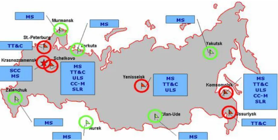
[image:26.596.63.523.413.645.2]The Russian GLONASS ground control segment consists of a system control centre located in Krasnoznamensk, a network of five telemetry, tracking and command centres, the central clock located in Schelkovo near Moscow, two laser ranging stations as well as a network of four monitoring and measuring stations. The Figure 8 below shows the location of these control centres and stations (Agency, 2011b).
Figure 1.8 – Location of control and command centres and stations within Russia
(Agency, 2011b).
27
The ground control segment is responsible for Beidou satellite systems operation and control. Furthermore, it consists of the Master Control Station, Time Synchronization/Upload Stations (TS/US) and Monitor Stations (Office 2013). The main control station main tasks include collecting observation data from the TS/US and monitoring stations to process the data, perform mission planning and scheduling, observe and calculate satellite clock bias and finally to monitor the satellite payload and analyse anomalies (Office 2013). The TS/US is used to measure the satellite clock biases and upload satellite NAV messages. Furthermore, main tasks of monitor stations are to continuously observe satellite NAV signals, and to provide real-time data to the Master Control Stations (Office 2013).
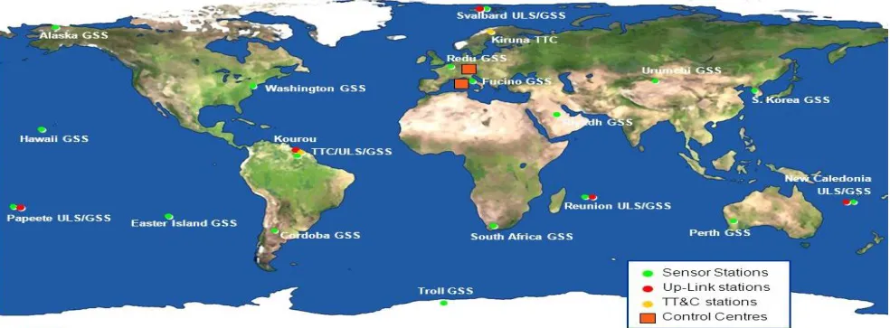
[image:27.596.65.557.516.698.2]The Beidou control segment is currently expanding as the Beidou-2 GNSS network evolves and is expected to be fully operational in the year 2020. Galileo will consist of two control centres and a global network of transmitting and receiving stations (Agency, 2011a). The two ground control centres (GCC) will manage control functions supported by a Galileo control system (GCS) and mission functions supported by a dedicated Galileo Mission System (GMS) (Agency, 2011a). The GMS will handle navigation system control while the GCS will handle spacecraft housekeeping and constellation maintenance (Agency, 2011a). As mentioned, and as with the other GNSS systems, the GCS is responsible for the management of satellites as well as constellation control. Its functional elements are deployed within the Galileo Control Centres (GCC) and the five globally distributed Telemetry Tracking and Control (TT&C) stations. To manage this, the GCS will use a global network of nominally five TTC stations to communicate with each satellite on a scheme combining regular, scheduled contacts, long-term test campaigns and contingency contacts (Agency, 2011a).
Figure 1.9 – Configuration of Galileo Ground Segment (Smet, 2009).
28
services which include:
The Galileo Open Service (OS) data which is a free and open service with high accuracy, however the integrity or quality of information cannot be guaranteed. These are
transmitted on the E5a, E5b and E2-L1-E1 carrier frequencies
Commercial Service (CS) data which are transmitted on the E5b, E6 and E2-L1-E1 carriers. The signal supports precise local differential applications using the open signal overlaid with the signal on E6 as well as supporting the integration of the Galileo
applications and wireless communication networks.
Safety of Life Services (SoL) comprises signal reliability data at a universal level. This further includes integrity and Signal in Space Accuracy (SISA) data.
Public Regulated Services (PRS) this service is intended for government, law enforcement, health services as well as a host of other industries, ultimately offering highly accurate and improved continuity of services. These signals are transmitted on the E6 and L1 carrier frequencies.
2.4 The User Segment
The User segment within the United States GPS Global Navigation Satellite System consists of the GPS receiver equipment, which receive signals from the satellites and uses the
transmission to calculate the users three dimensional position and time on the earth’s surface. This is very much similar with other currently available GNSS systems. Generally the user segment consists of hardware such as radio receivers, processors and antennas which are used to receive satellite signals and determine pseudoranges, and solve the navigation equations in order to obtain three dimensional coordinates and provide a very accurate time (GPS.gov, 2015).
2.5 Performance Analysis GNSS Systems Using PPP
29
and will be discussed later on.
One negative factor to PPP is the fact that current commercial software does not provide processing of measurements taken using PPP techniques. Processing is usually done using scientific software or one of several online PPP services (K. Dawidowicz, 2014). The main challenge of dual frequency precise point positioning is that it takes up to thirty minutes to obtain a centimetre level accuracy. As mentioned, PPP is one of two techniques used for high accuracy GNSS based positioning with the other being the network based Real Time
Kinematic (RTK). PPP is a powerful and efficient technology used for civilian and scientific applications worldwide. Although PPP has advantages such as high computational efficiency, not requiring dedicated reference stations it requires a long convergence time to achieve a desired accuracy (Pan Li 2014). The precise point positioning technique combines precise clocks and orbits calculated from a global network.
Pseudorange multipath and pseudorange noise are the largest remaining unmanaged error sources in PPP. It is believed that reducing the effects of multipath and noise on the
pseudorange observable, accurate estimates of carrier phase float ambiguities will be attained sooner, ultimately reducing the initial convergence period of PPP (Garrett Seepersad, 2014). With the use of modernized GPS, Beidou, Galileo and GLONASS there are several
advantages to be gained such as the availability of more visible satellites, greater signal power levels and more potential observable combinations, which may result in improved positional accuracy, availability and reliability. Both the pseudorange multipath and noise represent the largest remaining unmanaged error source in PPP. The amplitude of the multipath-induced errors in carrier phase observations is limited to a quarter wavelength or about 5 cm, but is typically well below 2 cm. Pseudorange multipath can have a magnitude of up to 10–20 m as it depends directly on the distance to the reflector. Currently, Hatch filtering is being performed in the position domain of the PPP software to mitigate pseudorange multipath and noise with minimal improvements in the rate of convergence (Garrett Seepersad, 2014). Pseudorange multipath and noise can be corrected using several different methods to ultimately reduce convergence times and increase accuracies.
30
Table 2.1
Raw pseudorange
correction
Same day
Running averaging
Multipath
Yes
Yes
Noise
Yes
Yes
Real time
No
Yes
Extra data required
Yes
No
Complexity
High
Medium
Limitations
Post-processing required Filter has a convergence period
% datasets improved
57
48
[image:30.596.59.517.331.479.2]Table showing Summary of examined methods to mitigate pseudorange multipath and noise by correcting the raw observables (Garrett Seepersad 2014).
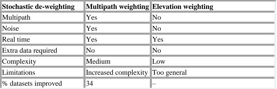
Table 2.2
Stochastic de-weighting
Multipath weighting
Elevation weighting
Multipath
Yes
No
Noise
Yes
No
Real time
Yes
Yes
Extra data required
No
No
Complexity
Medium
Low
Limitations
Increased complexity Too general
% datasets improved
34
–
Summary of examined methods to mitigate pseudorange multipath and noise by stochastically de-weighting observables (Garrett Seepersad 2014).
Multipath linear combination is used as shows in the tables above, through correcting the raw pseudorange observable through direct methodology, and the second being through
stochastically de-weight pseudorange observables. Through both these methods it was found through testing from Garrett Seepersad and Sunil Bisnath throughout their paper ‘Reduction of PPP convergence period through pseudorange multipath and noise mitigation’ that minimal improvements were noted using the multipath observable from the previous day. Using multipath from the same day was possible in real time and post processing modes which had an improvement rate of convergence for forty eight and fifty seven percent respectively, with an improvement in rate of convergence for thirty four percent of data was observed when pseudorange measurements were stochastically de-weighted using the multipath observable (Garrett Seepersad, 2014). Datasets with no improvements from directly correcting the raw pseudorange observables (43%) or stochastically de-weighting the pseudorange observables (66%) presented similar quality of results as the conventional PPP solution (Garrett
31
PPP is a cost effective technique enabling static, sub-centimetre horizontal and few centimetre vertical positioning with a single GPS receiver, unlike other methods such as relative GPS, RTK and Network RTK which require multiple receivers. PPP is used for processing static and kinematic data, both in real-time and post-processing. The downside however is the fact that PPP requires a lengthy initialisation period for the carrier phase ambiguities to converge to stable values and for position solution to reach its optimal precision (Garrett Seepersad, 2014).
2.6 Quality of AUSPOS Online PPP Software Coordinates
It has been documented by Geoscience Australia (GA) that the quality of computed coordinates using online PPP software will be dependent on a number of factors, including the proximity of International GPS (IGPS) station, the quality of these IGPS orbit products and finally the quantity of data submitted. According to GA observing for a period of twenty four hours using a single receiver should provide the user with an accuracy of approximately 0.010m and 0.030m in both the horizontal and vertical positioning respectively. Further, an approximation has been made for observation logging times of less than twelve hours may produce accuracies in horizontal and vertical positioning of 0.020m and 0.050m respectively. These approximations will be tested for accuracy and analysed in later chapters.
Further, research into the quality of vertical data provided by online PPP with particular focus on the AUSPOS software found that the heights that are derived from AUSPOS will not be
precisely matched to the Australian Height Datum (AHD) data provided by SCIMS. This is because AUSPOS computes the AHD value by subtracting the AUSGeoid98 site value from the processed ellipsoidal height. This will provide an approximation of AHD levels however
unfortunately is not near to exact values. To increase this accuracy GA recommends that if the station is greater than one hundred kilometres from the nearest IGS station, a longer
observation period will increase the accuracy of three dimensional coordinates.
2.7 Differential GNSS (DGNSS)
32
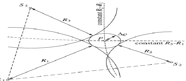
Figure 2.1 – Two dimensional pseudorange positioning. Centre of sphere is unknown
position with radius representing range correction, calculated using three satellites (Bernhard Hoffmann-Wellenhof, 2008).
Differential GNSS requires one or more observations to base stations with known coordinates with the data than processed by differencing pseudo-range or carrier phase observations for all stations, which can be single, double or triple differencing.
Single differencing takes simultaneous measurements to one satellite from two different receivers reducing satellite clock and orbiting errors as well as reducing atmospheric errors in shorter baselines. Double differencing is where observations are taken to two different satellites by two receivers simultaneously. A single difference is undertaken for each satellite between the observed differences observed by receiver one compared with that observed by the second receiver. This process eliminates satellite and receiver clock errors as well as the reduction and in many cases elimination of orbital errors and atmospheric variables. Finally, triple differencing is performed by taking the difference between two double differences separated by a time interval, eliminating all clock bias errors and the integer ambiguity as well as atmospheric delay errors, reducing satellite ephemeris.
2.8 Chapter Summary
The use of GNSS is becoming more dependent upon throughout our daily lives. These systems are used for many different applications ranging from transport such as automobiles, aircraft, boats, ships, cyclists as well as a host of other applications, perhaps more importantly the surveying and mapping industries.
33
well become a major supplier of Global Navigation Satellites Systems universally available within the next few years. Global Navigation Satellite Systems consist of three major
components or segments. These segments are known as the space segment, control segment and user segment. Each and every GNSS system must contain these components or
segments to be able to function and missing any one of these segments will result in the total collapse and failure of the system. Each and every system orbits there satellites at different orbital planes spread at slightly different angles to one another.
Precise Point Positioning is a technique used to try and achieve high accuracies in close to real time. The technique has become quite popular as it is capable of producing these high
accuracies of centimetre to sub centimetre positioning using a single GNSS receiver compared with differential positioning techniques. There are however negatives with this technique, the major issue being the length of time observations required to achieve centimetre level which at times may take in excess of thirty minutes. This unfortunately makes using the PPP technique unrealistic to use in real time, however where positioning may not be achieved due to lack of satellite visibility, and insufficient control quality within close proximity, this technique will provide the user with accurate reliable data where they may not have been in a position to do so using differential techniques. The combination of GNSS systems however hopes to
34
Chapter 3 – Methodology
3.1 Introduction
Although GNSS are currently in use and heavily relied upon within the surveying industry, particularly the construction, infrastructure and civil sectors, the technical aspects of these systems including their performances within robust and diverse terrain are usually
misunderstood. Surveyors will at some stage throughout there working careers work with GNSS systems and it is imperative that these systems are understood.
On this, the aim of the project is to provide relevant technical information on the performance of GNSS systems and their accuracies, both through single GNSS system and a combination of systems to test whether these combinations achieve quicker convergence, accuracy and reliability compared with the use of only a single system.
The chapter further details the testing methods adopted, the equipment that will be utilised, site locations, and the processing service chosen to reduce the static observations. To achieve this testing, single GNSS receivers were used to record static satellite observation data over known geodetic quality coordinated points. The data is than submitted as a RINEX file to AUSPOS, a free processing service available to users online.
With the Beidou and Galileo systems currently in the upgrading stage before they are fully functional and universally accessible, the performance analysis using the Precise Point
Positioning Technique as well as the testing of stand-alone verse combined GNSS systems will be completed with a focus on the United States NAVSTAR Global Positioning System (GPS) and the Russian GLONASS navigational systems.
This chapter will ultimately allow the viewer to understand how the project was developed and the testing procedures adopted. It will further provide the reader with an understanding of how the method will allow for the gathering of suitable and sufficient data in order to evaluate the performance of standalone verse combined GNSS systems.
3.2 Project Constraints
There are several factors that need to be taken into consideration for a suitable experimental design required for this study. These consideration governed the office and field equipment used as well as the survey marks selected for testing.
35
survey of Class A and above which according to the New South Wales Government Land & Property Information (LPI) are geodetic survey quality, which is ultimately the minimum standard acceptable when selecting suitable marks for testing.
To ensure multipath is eliminated from observations, the geodetic survey stations used require a clear, uninterrupted vision to the sky, be clear of obstruction and free from any potential causes of multipath. Further, as the stations will be occupied over prolonged periods of time it is
necessary to ensure that the sites chosen are deemed safe for leaving survey equipment on site without the threat of interference or damage. Due to the fact a minimum of two receivers are required to collect data simultaneously it is imperative that the two geodetic stations chosen are within close proximity to one another to ensure travel time between sites is achieved in a reasonable time, as well as minimize the effect of any potential atmospheric discrepancies between the sites. This requirement as mentioned, is due to the desire to carry out concurrent measurements and ensure logistical challenges of operation between one site and the other are overcome. By adhering to the above constraints and solutions this will enable the best chance of obtaining reliable accurate data, ultimately leading to accurate and precise solutions.
The equipment used has been restricted to availability and access provided by Ultimate
Positioning Group Pty Ltd. Only two trig stations will be used for survey and data collection due to the limited availability of receivers and geodetic quality control marks deemed suitable for use given the above constraints. The two trig stations chosen are 20km apart and travel between sites will take approximately half an hour satisfying the given constraints.
3.2.1
Equipment
Two Trimble R10 GNSS receivers utilising Trimble Access Version 2015 Firmware 3.0.2 have been made available by Ultimate Positioning Group Pty Ltd for use during the data collection process of the experiment. Further to the receivers, two tribrach’s are required to mount the receivers onto the trig stations. The receivers will be placed at the two trig station locations chosen for observation and data collection. Trimble Business Centre (TBC) software will be used to convert the raw field data observed by the receivers into a Receiver Independent Exchange Format (RINEX) file, which is the format required for processing using the free online PPP software AUSPOS.
3.2.2
Field Method
36
as the ellipsoid height (Mapping, 2014). The length of time required for accurate horizontal positioning is between the range of six to twenty four hours, and a minimum of twenty four hours for height. Through testing, Ebner and Featherstone conclude that observations with a length of two days or more were required to achieve accurate and reliable results (Ebner, 2008).
Further, it was found through Martin et al (2011) that a, minimum of twelve hours was required for accurate horizontal positioning, and twenty four hours continuous measurements for accurate vertical positioning which reflects the recommendations set out by the ICSM. The two testing methods and results achieved by the two studies show conflicting recommendations, and this study will aim to resolve or at the very least confirm these recommendations. With a restriction on equipment availability and time constraints, the study will focus on the ICSM and Martin et al (2011) recommendations.
Each trig station for this study was occupied with a receiver for a twenty four hour period at an observation epoch of thirty seconds remaining consistent with recommendations done in previous studies, providing consistent comparable data. Occupations have be undertaken on two separate dates for each site to test repeatability. The observations at each site have been taken
simultaneously ultimately ensuring the isolation of effects of error. Although the ideal scenario requires several receivers recording simultaneously through stand alone, followed by
simultaneous occupations of combined GNSS, due to constraints around equipment availability and time frame, only two receivers may be used and hence, one receiver will be observing GPS only data while the other receiver will read a combination of GPS, GLONASS and Beidou satellites, eventually comparing the accuracy and precision of standalone vs combined GNSS.
As mentioned, due to constraints around the availability of GNSS receivers and time limitations, a third station was occupied by both GPS and GNSS receiver for a total of four 12 hour periods. Hence, standalone and GNSS observations were taken in two 12 hour blocks each, over two consecutive days.
3.2.3
Survey Trig Station Sites
The trig station sites were chosen with several elements in mind including accessibility, distance between each station to minimise travel time, positional location for best possible quality of signal, and the quality and accuracy of marks provided from LPI which meet the standard required for testing, in this case the stations have a Class A accuracy.
37
MGA56 Easting: 338387.374 Northing: 6266328.481
AHD71 - Class B – Accurate AHD
AHD71 RL 157.345
Figure 3.1 – Aerial Photo of Cromer Heights Trig Station set atop cliff face clear of
obstruction.
Carrol Trig Station – TS1421 CARROL [P]
GDA94 - CLASS A – ORDER 1 – High precision National Geodetic Survey
Published coordinates as at 26
thAugust 2015
MGA56 Easting: 332106.053 Northing: 6265786.668
AHD71 - Class B – Accurate AHD
[image:37.596.59.525.126.234.2]AHD71 RL 165.773
Figure 3.2 – Aerial Photo of Carrol Trig Station set next to fire trail, showing light canopy cover.
Mccowen Trig Station – TS3018 MCCOWEN [P]
GDA94 - CLASS A – ORDER 1 – High precision National Geodetic Survey
Published coordinates as at 26
thOctober 2015
MGA56 Easting: 339054.780 Northing: 6273146.719
AHD71 - Class B – Accurate AHD
38
Figure 3.3 – Aerial Photo of Mccowen Trig Station set atop of rock cliff clear of obstruction and potential object interference.
3.3
Data Processing
3.3.1 Raw Data
The Trimble R10 receivers were set up to record and log the raw data in Trimble T02. This extension is than converted from the T02 file into a RINEX .15o extension file to enable compatibility with AUSPOS. In order to achieve this, the T02is reduced in Trimble Business Centre software, before being edited and converted into the appropriate extension for reduction in online processing software AUSPOS. Upon conversion to RINEX, a twenty four hour solution will be provided for each field data file which will be used to compare and analyse the results between each other and known SCIMS coordinates. These observations will be further
decimated into 1, 2, 6, 12 and 24 hours to test for convergence times and consistency in results.
3.3.2 Processed Data
In order to fulfil the commitments of the project, taking into consideration time constraints, the data will be processed using one single online service provider AUSPOS. Although it would have been ideal to process the data through several different online providers, this single provider and results provided will suffice the objectives of this research, maintaining consistency and accuracy of results provided.
3.3.3 Online PPP Post Processing Services – AUSPOS
39
data provided by the user as well as the fifteen nearest IGS and Asia Pacific Reference Frame (APREF) stations for reference stations and employs the double differencing technique in order to determine a precise solution. Coordinates of the IGS stations are constrained with
[image:39.596.60.495.201.362.2]uncertainties of one millimetre in the horizontal and two millimetres for the vertical. The figures 11 and 12 below shos the world wide positioning of IGS reference stations and APREF network in Australia respectively.
Figure 3.4 – IGS Tracking Network (Australia, 2015).
Figure 3.5 – APREF CORS Network in Australia – Pacific (Australia, 2015).
[image:39.596.59.541.404.595.2]40
(Australia, 2015).
3.3.4
Data Comparisons
Data analysis and comparisons of results were made in order to analyse and assess the
performance of single and combined GNSS observations. These comparisons were made at the one, two, six, twelve and twenty four hour marks. The aim of this data analysis is to compare the performance of standalone verse combined static GNSS observations and results over periods of time, providing the user with greater knowledge and confidence.
Raw data observations were taken on two separate days over a combined forty eight hour period, in order to examine the extent satellite configuration, atmospheric and multipath affect the accuracy and precision of single and combined GNSS systems. The dissected observation files of both GPS and combined GNSS are processed and compared for precision and accuracy based on a twenty four hour observation period as mentioned previously.
3.4
Chapter Summary
41
Chapter 4 – Results
4.1 Introduction
In this chapter, solutions obtained from the AUSPOS online post processing software will be compared in order to assess the various comparisons outlined in the aims and objectives earlier in the dissertation.
The result of these twenty four hour observations will be processed and presented as the best case solutions, ultimately creating a baseline of data where comparisons will be made between solution variations. Further, the results will be presented based on data types of GPS verse a combination of Global Navigation Satellite Systems. The results provided within this chapter will form the basis from which both comparisons and data analysis will be reviewed in chapter five.
At the conclusions of this chapter it is expected that the reader should have an understanding of solution bias, an overview of similarity in results obtained and the comparison between the SCIMS network and the solutions obtained.
4.2 Processed Solutions
AUSPOS provides solutions in both the GDA94 and MGA coordinate systems. The SCIMS coordinates provided are also in MGA format. Both the horizontal and vertical positioning provided by these two systems will be compared to one another. The vertical positioning will be in relation to the Australian Height Datum 1971 (AHD71). Further, the GPS only and combines GNSS observations will be compared to one another to analyse whether these systems provide similar or varying solutions.
4.3 Twenty Four Hour GNSS Observation Results (TS1421)
42
4.3.1
Carrol Trig Station (TS 1421) 24 hour combined GNSS observation
[image:42.596.57.552.145.448.2]solutions.
Figure 4.1 – Visual Comparison of TS 1421 SCIMS Coordinates and the combined GNSS
solutions provided by AUSPOS for data observed on two separate dates at the Carrol Trig Station (TS 1421).
43
4.3.2
GNSS Vs TS1421
Table 4.1 – GNSS AUSPOS solutions Vs TS 1421 SCIMS coordinates.
The results above show a comparison between the known TS 1421 trig station and solutions provided by AUSPOS. As we can see the solution at the twenty four hour mark are -0.018m and 0.013m in Easting and Northing respectively. We can see from the linear trend lines depicted above, that these lines are converging toward the zero line as observation time increases, indicating an increase in accuracy and reliability with prolonged observations. This is consistent with previous tests and studies completed.
1 2 6 12 24
Easting -0.041 -0.026 -0.023 -0.019 -0.018
Northing -0.002 0.001 -0.003 0.007 0.013
RL -0.129 -0.064 -0.032 -0.047 -0.052
-0.14 -0.12 -0.1 -0.08 -0.06 -0.04 -0.02 0 0.02 0.04
Dif
fe
re
n
ce
in
me
tres
(m
)
Difference Between observation time periods & SCIMS Coordinates
GNSS Vs TS 1421 SCIMS
Day 1
44
4.3.3
GNSS Day 2 Vs TS1421
Table 4.2 – GNSS AUSPOS solutions Day 2 Vs TS 1421 SCIMS coordinates.
The results above show similar results to field tests completed in day one. Results appear to increase in accuracy with longer observation times in particular with the solutions obtained for AHD heights.
4.3.4
GNSS Day 1 Vs GNSS Day 2 Solutions
Table 4.3 – GNSS Day 1 Vs GNSS Day 2.
1 2 6 12 24
Easting -0.024 -0.025 -0.013 -0.004 -0.007
Northing 0.027 0.020 0.010 0.021 0.019
RL -0.078 -0.001 -0.037 0.008 0.022
-0.100 -0.080 -0.060 -0.040 -0.020 0.000 0.020 0.040 Dif fe re n ce in me tres (m )
Difference Between observation time periods & SCIMS Coordinates
GNSS Vs TS 1421 SCIMS
Day 2
Linear (Easting) Linear (Northing) Linear (RL)
1 2 6 12 24
Easting -0.017 -0.001 -0.010 -0.015 -0.011
Northing -0.029 -0.019 -0.013 -0.014 -0.006
RL -0.051 -0.063 0.005 -0.055 -0.074
-0.080 -0.070 -0.060 -0.050 -0.040 -0.030 -0.020 -0.010 0.000 0.010 Dif fe re n ce in me tres (m )
Difference Between observation time periods & SCIMS Coordinates
GNSS Day 1 Vs GNSS Day 2
[image:44.596.62.530.486.770.2]45
Table 4.3 provides a comparison between the two independent field observations completed over the Carrol trig station. As expected we can see that the largest residuals occur within the one hour observation time and gradually reduce as observation time’s increase. There is a spike in the AHD RL row at the six hour observation time we see that this is not consistent with the vertical results at the other hour intervals. Data was processed for a second time to ensure no entry or user error was made, and the same results were achieved.
It is therefore possible that this outlier was a result of multipath error, due to the light overhead canopy over base station, or interference by a foreign object such as a bird or other object of some sort interfering with the receiver signal. Further, the outlier may have been the result of solar activity, and as both the standalone and combined sessions were conducted concurrently this result will be compared with that of the standalone at the six hour mark to find out whether or not solar activity may have indeed played a role or interfered with the result.
What has been made clear from the results provided above is the fact that the horizontal accuracy and precision improved with longer observation times, which is consistent with previous studies and assumptions made prior to undertaking these tests. The difference in horizontal positioning between the two field data files after twenty four hours of observation were -0.011m and -0.006m in Easting and Northing respectively, remaining consistent with
recommendations and assumptions made by the ICSM. Having said this, it is quite surprising considering my initial expectation prior to undertaking field observations was that the solutions derived between the 24hour solutions would be quite similar, <10mm in horizontal positioning to the SCIMS coordinates provided for TS 1421. This will be further assessed with the GPS only solutions.
Through analysing the results above there appears to be a bias toward the North and South using AUSPOS. This cannot be certain at this point, and further comparisons will be made with additional field tests to see whether or not a consistent pattern arises with the results indicating a bias in solution.
46
4.4 Twenty Four Hour GPS Observation Results (TS 10447)
The following information presents the processed 24 hour observation files for the standalone GPS system. Solutions for the 24 hour observation files were obtained using the AUSPOS online processing software. The solutions have been compared with the known SCIMS coordinates provided from the LPI website, as well as a further comparison between the two reduced field files, testing convergence times, repeatability, accuracy and performance of single systems.
[image:46.596.57.553.277.608.2]4.4.1
Cromer Heights Trig Station (TS 10447) 24 hour GPS observation
solutions.
Figure 4.2 – Visual comparison TS 10447 SCIMS Coordinates and the GPS only solutions
obtained by AUSPOS for data observed on two separate dates at the Cromer Heights Trig Station.
Figure 4.2 shows the separation between the TS 10447 SCIMS MGA coordinates, as well as the GPS only field observation coordinates provided by the online post processing software
47
Tables 4.4 and 4.5 below show the comparisons between the twenty four hour observations decimated into 1, 2, 6, 12 and 24 hour time slots, against the values of the known Carrol trig station coordinates (TS 10447). A further comparison was made between the two field data solutions obtained by AUSPOS to test for accuracy, precision and repeatability of data. This comparison can be seen in Table 4.6.
[image:47.596.61.525.189.502.2]4.4.2
GPS Day 1 Vs TS10447
Table 4.4 – GPS AUSPOS solutions Vs TS 10447 SCIMS coordinates.
The above results are consistent, to within <10mm of the results achieved when comparing between the GNSS solutions and its respective receiver. These observations were observed concurrently with the above GPS only field observations, ensuring any atmospheric conditions which may impact on results obsolete, providing a solid base on which results may be accurately and reliable compared. The results thus far provide an interesting insight into the reliability and perhaps accuracy of the known coordinates provided by SCIM