VII
ABSTRACT
6
Recent advancements In nanoscale physics have allowed researchers to
begin manipulating materials at the molecular level. This means that new
materials may be created that can conduct electricity very well while insulating against
heat transfer. This area of research will be discussed in more detail in the next section.
2.2 Waste Heat Recovery
In the case of TEG for waste heat recovery power generation, there have been
many conceptual designs of a power conversion system which are potentially capable of
obtaining application in this area. These designs involve the consideration of the
maximum power output and conversion efficiency with different thermoelectric heat
exchanger. Furthermore, performance evaluations of the thermoelectric generators have
been theoretically carried out by modeling approach. The results show that the
thermoelectric generators are promising devices for waste heat recovery. Although the
economic viability of a TEG may be improved significantly when used for waste heat
recovery, desirable TEG technologies for waste heat recovery are those that could
reduce the device cost and increase the conversion efficiency of a device. Therefore, one
of the more attractive options for waste heat recovery is to construct the TEG device by
incorporating the relatively simple parallel-plate heat exchanger with the commercially
available thermoelectric modules.
According to Crane (2004), the TEG module to optimize TE waste heat recovery
by integrating efficient cross flow heat exchangers with thermoelectric modules for
conversion of waste heat to electricity. Numerical heat exchanger models are integrated
with models for Bi2Te3 TE modules, which are positioned between the hot and cold flow
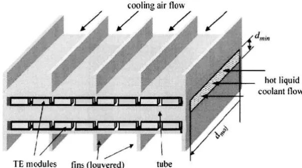
streams as shown in the schematic of a heat exchanger sub-section in Figure 1. It
indicates fins on the air side passages, which are often louvered (not shown in the
illustration) to enhance heat transfer, since air side cooling typically presents the highest
7
oxide layers on both the outer surface of the metal tubes, which hold the hot fluid, and
the inner surface of the outer metal wall, which supports the fins for air side cooling.
TE modules fins (louvered) tube
hot liquid
[image:19.612.120.423.164.332.2]cOQlant flow
Figure 2.1 : Sub-section of thermoelectric heat exchanger (Source: Crane, (2004»
2.3 Thermoelectric Device
There are two types of thermoelectric devices are thermoelectric generation and
thermoelectric cooling.
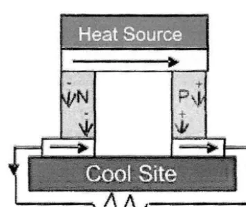
2.3.1 Thermoelectric Generation
The simplest thermoelectric generator consists of a thermocouple (thermopile)
comprising a p-type and n-type semiconductor connected electrically in series and
thermally in parallel. Heat is pumped into one side of the couple and rejected from the
opposite side. An electrical current is produced, proportional to the temperature gradient
between the hot and cold junctions. a thermoelectric generator utilizing semiconductors
8
energy machine and the input, in energy terms = Pout !Pin. Generally, conversIon
efficiency is a dimensionless number between 0 and 1.0 or 0 to 10(010). The
thermoelectric generator shows further possible improvement in his performance.
[image:20.628.166.344.206.355.2](Source : Gaffar, (2007))
Figure 2.2 : Principle of Thermoelectric Generation (Source: Gaffar, (2007))
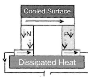
2.3.2 Thermoelectric Cooling
If an electric current is applied to the thermocouple as shown, heat is pumped
from the cold junction to the hot junction. The cold junction will rapidly drop below
ambient temperature provided heat is removed from the hot side. The temperature
gradient will vary according to the magnitude of generation current applied (Soobeck
9
~
C
ooled Surfa~e
~-'---'.-.-'---' -'
---N
-t
[image:21.629.164.348.126.286.2]--.-~
Figure 2.3: Principle of Thermoelectric Cooling (Source: Gaffar, (2007»
2.4 General Concept ofTbermoelectric Generators for Vebicles
A well-known rule of energy balance in internal combustion engine that the
power available for driving the vehicle is one third at the most, the remaining two thirds
are evolved rough equally as waste heat in the exhaust stream and latent heat in the
coolant system.
According to Rowe (2006), for a typical 100 hp engine generating 75 kW in
terms of electric power, roughly 50 kW is evolved as waste heat energy. Evidently even
if only a small fraction of this can be recovered, a substantial amount of electrical power
could be generated.
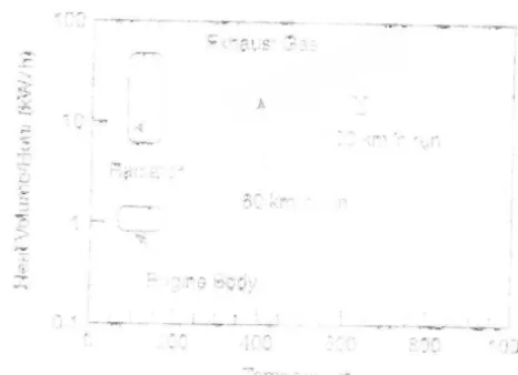
The Figure 2.4 shows the amount of heat per hour (kW/h) versus temperature for
a 2000cm3 class passenger car. It is shown that the exhaust gas possesses high heat
energy corresponding to 10 kW/h at exhaust gas temperature 400°C and 100 kW/h at
620°C when running at 32.4 miles an hour (60 km/h) on a flat road. The heat energy of
10
through a thermoelectric stack (TE Stack) which is a united system of thermoelectric
modules and a heat exchanger.
}.
[image:22.620.134.367.165.334.2]' . ...;.
Figure 2.4 : Exhaust heat volume per hour temperature for a 2000cc car.
(Source: Rowe, (2006»
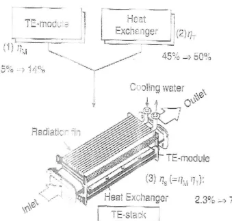
The Figure 2.5 shows the basic structure of a TE Stack and its heat balance. In
this system, the overall efficiency of the TE Stack can be obtained as a product of the
efficiencies of the thennoelectric modules and heat exchanger. In this heat balance
model,
Q
gas-in andQ
gas-out are the amounts of heat at the inlet and outlet of heatexchanger, respectively QI and Q2 are the radiation losses from the side of the legs, and
P is the electrical output power. If we assume that Q gas-out is 45% and Q2 ( the radiation
heat loss from the side of the heat exchange) is 10%, the net amount of heat (Qe) , which
>.>
...• .r~'
L
: I
'
j
I
I:
i ,~
rI
-
-
h
He
a
t
:.
'-C-Yt" /\v . "tc.. -Inr'''';j~' f
[image:23.618.86.426.125.448.2]H
ea
t
Ex
c
h
anger
Figure 2.5 : Structure of thermoelectric with a heat exchanger
(Source: Rowe, (2006»)
2.5 Automotive Waste Heat Energy Recovery
11
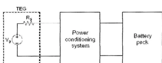
According to Yu and Chau (2009), a practical automotive waste heat energy
recovery system consists of an exhaust gas system, a heat exchanger, a TEG system, a
power conditioning system, and a battery pack. There are various considerations and
12
• A typical exhaust gas system for internal combustion engines is composed of the
exhaust manifold, exhaust pipe, catalytic converter, center muffler and rear
muffler. It is a natural choice that the heat exchanger should be installed at the
location
with
the highest temperature, namely at the exhaust manifold. Takinginto account the working temperature of the TEG device and the convenience of
mounting the heat exchanger, a compromise may be required on the selection of
heat exchanger location.
• The TEG system is governed by the selected TE materials which need to offer
high energy conversion efficiency. In recent years, the characteristics of
thermoelectric materials have been significantly improved in teITIlS of both the
ZT value and the temperature range. For example, the p-type and n-type Bi-Te
materials offer the optimal ZT values at the temperature range of exhaust gas.
• Rather than directly connecting the TEG system to the battery pack, a power
conditioning system needs to be installed between them. This power
conditioning system functions to regulate the power flow in such a way that the
maximum power transfer can be achieved. The two key issues are the design of
a proper power converter and the devise of an effective control algorithm, which
will be discussed later.
TEG
r-.... --''''''---..,. .... _-,
1 K'S '
!
t
'
/
/
·
·
."
I 'Ii_ l-4-""\ i o:~. I
I
.
~
r
I:
~;
.
b,;_~=..:::.,;:;:.;.;_=-.::.J
P';::'''<'i'€(
c(?fiditi0ning ':;'yst;3j'jj
Batte-
f,
[image:24.618.115.397.550.661.2]Pi:1C"""'~