UNIVERSITI TEKNIKAL MALAYSIA MELAKA
DESIGN AND FABRICATION OF A CHECKING FIXTURE FOR
A PRESS PART COMPONENT
This report submitted in accordance with requirement of the Universiti Teknikal Malaysia Melaka (UTeM) for the Bachelor Degree of Manufacturing Engineering
(Manufacturing Design) with Honours.
by
IDRIS BIN SAARAN
i
ABSTRACT
ii
ABSTRAK
iii
ACKNOWLEDGEMENTS
Dear Mum and Dad at Jelebu, Negeri Sembilan, thanks for your prayers, blessing, and financial support. Not to forget my siblings that gives me a support when each time I’m feeling down. To all my friends, thanks a lot for sharing an idea to complete this thesis.
iv
TABLE OF CONTENTS
Abstract ... i
Abstrak ... ii
Acknowledgement... iii
Table of Content ... iv
List of Tables... viii
List of Figures ... ix
List of Abbreviations... xii
1. INTRODUCTION ... 1
1.1 Background ... 1
1.2 Problem Statement ... 2
1.3 Objectives of the Project ... 2
1.4 Scopes and Key Assumption ... 3
1.5 Importance of the Study ... 3
1.6 Gantt Chart for PSM 1 ... 4
1.7 Gantt Chart for PSM 2 ... 5
1.8 Summary ... 6
2. LITERATURE REVIEW... 7
2.1 Introduction ... 7
2.2 Element of Fixtures ... 11
2.2.1 Locators and Support ... 11
2.2.2 Locating the Work... 12
2.2.2.1 Locating From a Flat Surface ... 13
2.2.2.2 Locating From an Internal Diameter ... 14
v
2.2.3 Clamping and Workholding Principles ... 19
2.2.4 Types of Clamp ... 19
2.2.4.1 Strap Clamp ... 19
2.2.4.2 Screw Clamp ... 20
2.2.4.3 Swing Clamp ... 22
2.2.4.4 Hook Clamp ... 22
2.2.4.5 Quick Acting Knob ... 23
2.2.4.6 Cam Action Clamp ... 24
2.2.4.7 Wedge Clamp ... 25
2.2.4.8 Toggle Action Clamp ... 26
2.2.4.9 Power clamp ... 26
2.2.5 Body of Fixtures ... 27
2.2.5.1 Cast Fixture Bodies ... 28
2.2.5.2 Welded Fixture Bodies ... 28
2.2.5.3 Built-up Fixture Bodies ... 28
2.3 Material of Fixture ... 29
2.3.1 Araldite ... 29
2.3.2 Delrin ... 30
2.3.3 Mild Steel ... 34
2.3.4 Aluminum ... 34
2.4 Computer Numerical Control (CNC) ... 35
3. METHODOLOGY ... 38
3.1 Introduction to Methodology ... 38
3.2 Execution of Project ... 40
vi
4.1 Introduction ... 41
4.2 Design of Checking Fixture ... 41
4.2.1 Caster Drawing... 41
4.2.2 Checking Fixture Design-First Design... 43
4.2.3 Design Improvement ... 46
4.2.3a Fixture Body ... 46
4.2.3b Clamping Mechanism ... 48
4.2.3c Base Plate ... 48
4.2.3d Support Plate ... 49
4.2.3.e Pin and Pin Holder ... 49
4.2.3f Clamp Bracket ... 50
4.3 Preparation of CNC Program ... 51
4.3.1 Converting Solidwork Part Drawing to Catia Part ... 51
4.3.2 Machining Program & Simulation ... 52
4.4 Fabrication of Checking Fixture ... 54
4.4.1 Fabrication of Fixture Body ... 54
4.4.2 Fabrication of Base Plate and Support Plate ... 55
4.4.3 Fabrication of Clamp Bracket ... 57
4.4.4 Fabrication of Clamp Bracket Stand ... 58
4.4.5 Fabrication of Pin ... 59
4.4.6 Fabrication of Fixture Body Stand ... 60
4.4.7 Fabrication of Holder ... 61
4.4.8 Assembly of Checking Fixture ... 62
4.5 Summary ... 63
5. DISCUSSION ... 64
5.1 Introduction ... 64
vii
5.3 Preparation of CNC Program ... 66
5.4 Fabrication of Checking Fixture ... 66
5.5 Method of Inspection ... 68
5.6 Summary ... 69
6. CONCLUSION ... 70
6.1 Conclusion ... 70
6.2 Recommendation... 71
REFERENCES ... 72
APPENDICES
A Caster
B Isometric View of Checking Fixture C Fixture Body
D Base Plate E Support Plate F Pin
viii
LIST OF TABLES
1.1 Gantt chart PSM 1 4
1.2 Gantt chart PSM 2 5
2.1 Elements Should Be Considered in Selection of Locator and Support 11 2.2 Clamping forces generated by screw 21 2.3 Properties of Delrin AF Blend 33 2.4 Mechanical Properties of Mild Steel 34 2.5 Mechanical Properties of Aluminum 35 2.6 Coding for Preparatory Function 37 2.7 Coding for Miscellaneous Function 37
4.1 Process Planning 53
ix
LIST OF FIGURES
2.1a Example of Checking Fixture 8 2.1b Example Design of Checking Fixture 8 2.1c Checking Fixture Design and Component 9 2.1d Example of Checking Fixture for Car’s Front Bumper 9 2.2 Components of Jig and Fixture 10 2.3a Types of Solid Support 13 2.3b Types of Threaded Adjustable Support 13
2.3c Equalizing Support 14
2.4a Internal Locators 15
2.4b Pin Locators and Bushing 15 2.4c Combined Used of Round and Relieved Locator 16 2.4d Types of Relieved Locator 16
2.5a Nesting Locator 17
2.5b Vee Locator 17
2.5c Fixed-stop Locator 17
2.5d Installed Fixed-stop Locator 18 2.5e Adjustable-stop Locator 18
2.5f Sight Locator 18
2.6a Strap Clamp 20
2.6b Three Classes of Lever of Strap Clamp Mechanisms 20 2.7 Application of Screw to Clamping a Part 21
2.8 Swing Clamp 22
2.9a Hook Clamp 23
2.9b Modified Hook Clamp 23
2.10 Quick-Acting Knob 24
2.11a Flat Eccentric Cam 24
2.11b Flat Spiral Cam 25
2.11c Cylindrical Cam 25
x
2.13 Toggle-Action Clamp 26
2.14 Power Clamping Mechanism 27 2.15a Application of Epoxy Resin in Semiconductor Product 29 2.15b Application of Epoxy as Adhesion 30 2.16a Delrin in Blue Color and Machined 31 2.16b Delrin Material in White Color 31 2.16c Various Shapes and Colors of Delrin 32 2.17a HAAS Machining Center 36
2.17b HAAS Turning Center 36
3.1 Process Flow Chart of Project Execution 39
4.1 Isometric View of Caster 42
4.2 Datum of Part 42
4.3 Distance of Two Hole 43
4.4 Distance of Bigger Contour 43 4.5 Fixture Assemblies of First Design 45
4.6 Fixture Body 46
4.7 Assemblies of New Checking Fixture 47
4.8 Toggle Clamp 48
4.9 Base Plate 48
4.10 Support Plate 49
4.11a Pin 50
4.11b Holder 50
4.12 Clamp Bracket 51
4.13 Step to Convert File 52
4.14 Workpiece Zero Position of Part 52
4.15 Limiting Contour 53
4.16 Indicate The Tool Path 54 4.17 Process Flow of fixture body fabrication 55
4.18 Fixture Body 55
xi
4.21 Process Flow of Clamp Bracket Fabrication 57 4.22 Fabricated Clamp Bracket 58 4.23 Fabricated Clamp Bracket Stand 58 4.24 Process Flow of Clamping Bracket Stand Fabrication 59 4.25 Process Flow of Pin Fabrication 60
4.26 Fabricated Pin 60
4.27 Process Flow of Fixture Body Stand Fabrication 61 4.28 Fabricated Fixture Body Stand 61 4.29 Process Flow of Holder Fabrication 62
4.30 Fabricated Holder 62
4.31 Checking Fixture 63
5.1 Stress Occur on Caster 65
5.2 Fixture Body 66
5.3 Side View of Fixture Body 67
xii
LIST OF ABBREVIATIONS
CNC - Computer Numerical Control CAD - Computer Aided Design
CADCAM - Computer Aided Design and Computer Aided Manufacturing CMM - Coordinate Measuring Machine
CPU - Computer Processing Unit AISI - American Iron and Steel Institute POM - Polyoxymethylene
1
CHAPTER 1
INTRODUCTION
1.1 Background
In this several decades, manufacturing sector was expanded widely. It was generated through as an expanded of global economy. The first and third country is developed through the manufacturing sector which is validated for today. Because of the manufacturing sector expanded widely, many industries in manufacturing sector are developed. For examples are automotive, electronics, metal fabrication, and plastics. Mostly, all product manufactured are necessary an inspection process in order to conform the quality of the product. Many kind of inspection method are using such as visual inspection and through a conformance gauge. Therefore, a checking fixtures or jigs are built to fulfill the needs of the industry.
2 1.2 Problem Statement
When a products are manufactured through a press machine, inspection and checking process is needed in order to conform the products are meet the specification and dimension. Some products and data are able to inspect through a visual inspection but this method is just suit to the non-counted data, although it is the simplest way and less cost. Therefore, design a fabrication of a checking fixture is necessary to meet the needs of better inspection process. Through the use of checking fixture, products are inspected in allowable variations, although a fixture is design and fabricated with certain tolerances. It is because the products should be passes the inspection of several point on the products that fit to the quality data.
1.3 Objectives of the Project
The main objectives of this project study are to design and fabricate a checking fixture for a caster. The outcomes of this project study will be:
i. Design a checking fixture for a press caster.
ii. To Make a CNC program of machining process of checking fixture.
3 1.4 Scope and Key Assumptions
The scopes of this project are:
i. To Create a CAD data from physical model of wheel caster through a manual drawing using Solidwork.
ii. To design a checking fixture and generate CNC program using CADCAM software.
iii. To fabricate a checking fixture and validate the checking fixture accuracy using Coordinate Measuring Machine (CMM).
1.5 Importance of the Study
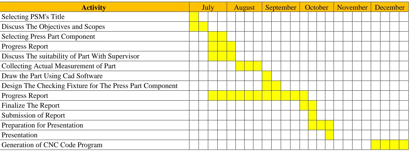
4 1.6 Gantt Chart for PSM 1
Table 1.1: Gantt chart PSM 1
Activity July August September October November December
Selecting PSM's Title
Discuss The Objectives and Scopes
Selecting Press Part Component
Progress Report Discuss The suitability of Part With Supervisor
Collecting Actual Measurement of Part
Draw the Part Using Cad Software
Design The Checking Fixture for The Press Part Component
Progress Report
Finalize The Report
Submission of Report
Preparation for Presentation Presentation
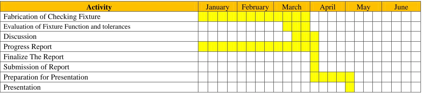
5 1.7 Gantt Chart for PSM 2
Table 1.2: Gantt chart PSM 2
Activity January February March April May June
Fabrication of Checking Fixture Evaluation of Fixture Function and tolerances
Discussion
Progress Report Finalize The Report
Submission of Report
6 1.8 Summary
7
CHAPTER 2
LITERATURE REVIEW
2.1 Introduction
A press is a process of changing a shape of sheet metal using a force according to the shape of dies which this process is widely used in industrial practice. Most of automotive parts and metal base product are manufactured using this method. For an automotive part that produced using this technique are car’s door components, bracket for mounting engine parts, engine mounting base, etc. For metal base product that manufactured via this method are aluminum home sink, CPU casing, door knob components, etc.
At manufacturing practice, a quality conformation on the part manufactured using press method is inspected through a special tool called checking fixture. This tool is designed and fabricated for locating, holding and then checking a certain points on part. There are two types of checking fixture which the first is gauging fixtures and measuring fixtures. Gauging fixtures used to check the part against a standard of known size and can only determine if a part is in or out of tolerance and measuring actually measure a part and can indicate exactly where and by how much a part is out of tolerance.
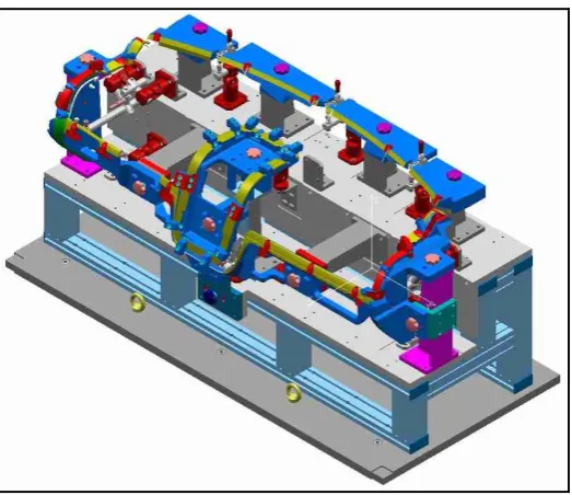
8
Figure 2.1(a): Example of checking fixture
[image:24.595.176.463.68.298.2] [image:24.595.189.451.346.572.2]