Commission of the European Communities
nuclear science
and technology
The Community's
research and development programme on
decommissioning of nuclear power plants
Commission of the European Communities
nuclear science
and technology
The Community's
research and development programme on
decommissioning of nuclear power plants
Fourth annual progress report (year 1983)
íVVSí
Directorate-General
Science, Research and Development
Published by the
COMMISSION OF THE EUROPEAN COMMUNITIES Directorate-General
Information Market and Innovation Bâtiment Jean Monnet
LUXEMBOURG
LEGAL NOTICE
Neither the Commission of the European Communities nor any person acting on behalf of the Commission is responsible for the use which might
be made of the following information
Cataloguing data can be found at the end of this publication
Luxembourg, Office for Official Publications of the European Communities, 1985 ISBN 92-825-4947-X Catalogue number:
FOREWORD
This is the fourth progress report of the European Community's pro-gramme (1979-1983) of research on the decommissioning of nuclear power plants. It covers the year 1983 and follows the 1980, 1981 and 1982 Reports (Ref. 1, 2, 3).
The Council of the European Communities had adopted the programme in March 1979 (Ref. 4 ) , considering:
"Certain parts of the nuclear power plants inevitably become radioac-tive during operation; it is therefore essential to find effecradioac-tive solutions which are capable of ensuring the safety and protection of both mankind and the environment against the potential hazards in-volved in the decommissioning of these plants."
The programme sought to promote a number of research and development projects as well as the identification of guiding principles. The projects concern the following subjects:
Project N° 1: Long-term integrity of buildings and systems; Project N° 2: Decontamination for decommissioning purposes; Project N° 3: Dismantling techniques;
Project N° 4: Treatment of specific waste materials: steel, concrete and graphite;
Project N° 5: Large transport containers for radioactive waste pro-duced in the dismantling of nuclear power plants;
Project N° 6: Estimation of the quantities of radioactive waste arising from decommissioning of nuclear power plants in the Community;
Project N° 7: Influence of nuclear power plant design features on decommissioning.
The research was carried out by public organizations and private firms in the Community under cost-sharing contracts with the Commission of the European Communities. The Commission budget for this five-year programme amounted to 4.7 million ECU.
The Commission has been responsible for managing the programme and was assisted in this task by an Advisory Committee on Programme Management, which consisted of experts appointed by the Member States' governments and of Commission officials.
The 1980, 1981 and 1982 Reports described the work programmes of most research contracts and initial results of the research.
The present report describes the further progress of research and contains a large amount of results. For a majority of the 51 research contracts composing the 1979-1983 programme, work was completed by the end of 1983; the conclusions drawn from this work are in this report.
Readers wishing complementary information are referred to the final contract reports, a number of which have already been published (see References at the end of the present report), and to the Proceedings of the International Conference on the Decommissioning of Nuclear Power Plants that the Commission of the European Communities organized on 22-24 May 1984, in Luxembourg.
Further research and development work is to be carried out under the new five-year (1984-1988) programme on the decommissioning of nuclear installations.
The Commission staff in charge of the programme during 1983 and of editing this report were: E. Huber, K.H. Schaller, R. Bisci and K. Pflugrad, Finally, the Commission wishes to express its gratitude to all the scien-tists of the contractors who have contributed to this report.
B. Huber
Head of the Programme
S. Orlowski Head, Division
"Nuclear Fuel Cycle"
CONTENTS
Page
1. PROJECT N° 1 : LONG-TERM INTEGRITY OF BUILDINGS AND SYSTEMS 1
1.1. Degradation of building plant and materials 1 1.2. Long-term integrity of buildings and systems 3
2. PROJECT N° 2: DECONTAMINATION FOR DECOMMISSIONING PURPOSES 6 2.1. Decontamination of concrete surfaces by flame-scarfing 6 2.2. Erosion of metal surfaces by cavitation at very high velocity 8
2.3. Composition of contamination layers and efficiency of
decontamination 10 2.4. Vigorous decontamination tests of steel samples in a special
test loop , 12 2.5. Development of economical decontamination procedures 18
2.6. Development of gel-based decontaminante 19 2.7. Metal decontamination by chemical and electrochemical
methods and by water lance 20 2.8. Delegation of an expert to the US-NRC in relation to the
clean-up of TMI-2 plant 23
3. PROJECT N° 3: DISMANTLING TECHNIQUES 27 3.1. Plasma techniques for cutting mineral and metal materials ... 27
3.2. Diamond-tipped saws for cutting concrete structures 29 3.3. Plasma-oxygen cutting of steel pressure vessels 33 3.4. Dismantling of concrete structures and metal components
using laser 35 3.5. Explosive demolition techniques for concrete structures 37
3.6. Cutting of steel components by intergranular fissuration .... 40 3.7. Review of systems for remotely controlled decommissioning
operations 42
4. PROJECT N° 4: TREATMENT OF SPECIFIC WASTE MATERIALS: STEEL,
CONCRETE AND GRAPHITE 46 4.1. Assessment of management modes for graphite waste 46
4.2. Treatment of contaminated steel waste by melting 48 4.3. Cobalt removal from steel by a melting process 55 4.4. Treatment of concrete with silicate solutions to prevent
dusting 56 4.5. Coating of materials to protect against corrosion, fix
contamination and avoid powder formation 59 4.6. Immobilization of contamination on metals by coating
with thermosetting resins 60 4.7. Design of an installations for the melting of radioactive
steel waste 63
5. PROJECT N° 5: LARGE TRANSPORT CONTAINERS FOR RADIOACTIVE WASTE
PRODUCED IN THE DISMANTLING OF NUCLEAR POWER PLANTS 66 5.1. System of large transport containers for waste from
6. PROJECT N° 6: ESTIMATION OF THE QUANTITIES OF RADIOACTIVE WASTE ARISING FROM THE DECOMMISSIONING OF NUCLEAR POWER PLANTS IN THE
COMMUNITY 74 6.1. Activation products in the biological shield of the Lingen
reactor 74 6.2. Activation products in the biological shield of the KRB-A
reactor 77 6.3. Activation and radiation at the Garigliano reactor pressure
vessel 79 6.4. Trace element assessment of low-alloy and stainless steels
with reference to gamma activity 81 6.5. Determination of trace elements in concrete samples from
various nuclear power plants 87 6.6. Methodology for evaluating radiological consequences of the
management of low-level radioactive waste from the
disman-tling of nuclear power plants 89 6.7. Review of techniques for measuring very low-level
radioac-tivity in relation to decommissioning 94
7. PROJECT N° 7: INFLUENCE OF NUCLEAR POWER PLANT DESIGN FEATURES ON
DECOMMISSIONING 97 7.1. Catalogue of design features facilitating decommissioning of
AGRs 97 7.2. Design features of civil works of nuclear installations
facilitating their eventual refurbishing, renewal,
dismantling or demolition 100 7.3. Erosion-corrosion testing of cobalt-free materials to
substitute cobalt alloys 104 7.4. The control of cobalt and niobium content of reactor-grade
steels 105 7.5. Removable coatings for the protection of concrete against
contamination 106 7.6. Characterization and improvement of coatings protecting
concrete against contamination 108 7.7. Evaluation of design features facilitating the
decommission-ing of PWRs 110 7.8. Concepts minimizing the activation of the biological shield.. 113
7.9. Biological shield design with dose-reducing effect in
decommissioning 114 7.10. Documentation system for decommissioning of nuclear power
plants 117
REFERENCES 122
ANNEX: MEMBERS OF THE ADVISORY COMMITTEE ON PROGRAMME MANAGEMENT IN
1. PROJECT N° 1; LONG-TERM INTEGRITY OF BUILDINGS AND SYSTEMS
It has been proposed that the dismantling of nuclear power plants be delayed for periods ranging from several decades to about a hundred years. Thereupon, radiation having largely died away, the dismantling would be easier and the radiation exposure of the dismantling workers would be less.
In this connection, measures are being studied to determine which ones are necessary to maintain retired plants in a safe condition over long periods. Particular attention is paid to the integrity of buildings and systems which contain the radioactive material (e.g. reactor building, reactor cooling system).
1.1. Degradation of Building Plant and Materials
Contractor: Central Electricity Generating Board, Barnwood, United Kingdom Contract N°: DE-A-001-UK Work Period: April 1980 - December 1983
1.1.1. Objective and Scope
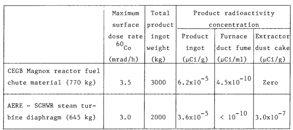
The objective of this research is to establish the life cycle of existing nuclear power station buildings and ensure that specifications for new station buildings list materials that are suitable for a long life with minimum maintenance. Wherever possible, the research should aim at ensur-ing that the specified materials attract surface contamination only or induced activity which decays rapidly.
Long life maintenance treatment for retained plant and buildings for safety and security purposes will be researched, to enable future mainten-ance and surveillmainten-ance to be kept within reasonable economic limits. The types of nuclear power plants concerned by this research are Magnox reac-tors and Advanced Gas-cooled Reacreac-tors.
1.1.2. Work Programme: See Ref.l, Paragraph 1.1.2.
1.1.3. Progress and Results
least 50 years assuming adequate maintenance is provided.
In-situ tests carried out were ultrasonic pulse velocity tests on concrete, covermeter surveys on reinforced concrete, carbonation tests on concrete, inspection of steelwork for corrosion and fatigue cracks, inspec-tion of precast concrete panel fixings for corrosion, inspecinspec-tion of metal window frames for corrosion.
Samples removed for testing comprised diamond-drilled concrete cores, mastic asphalt samples from roofs, fixing bolts from asbestos cement cladding, retaining bolts from patent glazing, samples of dry pack mortar bedding from precast concrete panels and a ground-water sample.
Laboratory testing of concrete cores included density measurements, compressive strength measurement, ultrasonic pulse velocity testing, aggregate/cement ratio measurement and chloride ion measurement. Mastic asphalt samples were tested for hardness, soluble binder content and aggregate grading. Fixing bolts were examined microscopically for corro-sion. The ground-water sample was analysed for sulphate content.
Following an inspection of Oldbury power station reactor buildings in January, detail proposals for the locations and type of samples and the nature of in-situ and non-destructive tests were made by the specialist testing contractor and were subsequently approved. The sampling and in-situ testing of the materials in N° 1 reactor building were successfully completed in May. The samples were tested during June and the contractor's report was issued in August. The reactor building was found to be in good condition and, if given adequate maintenance, unlikely to suffer from any major deterioration for the next 50 years.
At Oldbury, the in-situ tests carried out were ultrasonic pulse velocity tests on concrete, covermeter surveys on reinforced concrete, carbonation tests on concrete, hardness tests on concrete, inspection of structural steelwork for corrosion and fatigue cracks, internal and extern-al examinations of steel cladding panels for deterioration and inspection of metal window frames for corrosion.
Samples removed for testing comprised diamond-drilled concrete cores, mastic asphalt samples from roofs and ground-water samples.
aggregate grading. The ground-water samples were analysed for pH value and sulphate content.
An inspection of the reactor buildings at Dungeness 'A' power station was made in April, following which detailed proposals for locations and types of samples and the nature of in situ non destructive tests were subsequently approved and sampling and in-situ testing in N° 2 reactor building were carried out during September. Laboratory testing was comple-ted in October and a report produced by the specialist testing contractor. The condition of the building was considered to be satisfactory for its age and unlikely to suffer from any major deterioration for at least 25 years, on the assumption that adequate maintenance will be provided.
In-situ tests comprised ultrasonic pulse velocity tests on concrete, covermeter surveys on reinforced concrete, carbonation tests on concrete, examination of steel cladding panels for deterioration, examination of patent glazing for corrosion and inspection of internal brickwork, door lintels for cracking.
Samples removed for testing were diamond-drilled concrete cores and mastic asphalt samples from roofs.
Laboratory testing of concrete cores included density measurement, compressive strength measurement, ultrasonic pulse velocity testing, aggregate/cement ratio measurement and chloride ion measurement. Mastic asphalt samples were tested for hardness, soluble binder content and aggregate grading.
1.2. Long-term Integrity of Buildings and Systems
Contractor: Commissariat à l'Energie Atomique, Etablissement de la Vallée du Rhône, France
Contract N°: DE-A-002-F Work Period: January 1981 - March 1984
1.2.1. Objective and Scope
The aim of this study is to improve the knowledge of the aging of nuclear plant and to propose preventive measures for maintaining such plant in a satisfactory condition. The results should make it possible to choose the best decommissioning strategy (deferred or prompt dismantling) and to provide recommendations for the design of new plants.
document has to deal with:
- identification of the plant components the safety barriers rely on, in case of Stage 1 (maintenance of the plant in a satisfactory condition) or Stage 2 (long-term containment) of decommissioning; - causes of aging and damaging effects, due to aggressive agents to be
considered depending on the nature of the components (concrete, steel...);
- measures to prevent or to cure these effects in order to maintain the plant in safe conditions at Stage 1 or Stage 2.
The results expected from this analysis are:
- elements for estimating the maintenance and surveillance cost;
- elements for choosing the decommissioning stage and the delay suitable to achieve Stage 3 (complete removal);
- information for the design of new plants, facilitating their future decommissioning.
1.2.2. Work Programme: See Ref.l, Paragraph 1.2.2.
1.2.3. Progress and Results
The reported work relates to a 900 MWe PWR plant as a reference.
1.2.3.1. Functions to be kept operational
This subject was completed with the study of the confinement and maintenance of contaminated circuits and with the cost estimate of the various decommissioning steps.
An intermediate decommissioning stage specific for the reference reactor, called "Reinforced Stage 1", is being proposed. The operations necessary for this stage and its consequences were described, e.g.:
- circuit draining, setting of barriers between circuits and drying to minimise corrosion effects;
- radiological and thermal consequences of draining; in particular removal of the decay heat from the pressure vessel and core struc-ture activation;
- periodical control and preventive maintenance of circuits and their main components;
1.2.3.2. Radioactivity inventory
The PWR primary circuit radioactivity inventory was completed with the activity of the pressure vessel and the core structures (mainly cobalt- 60) and the calculation of the dose rate and its evolution with time.
1.2.3.3. Relationships between postponement times and their consequences The factors to be considered in selecting the decommissioning stage and waiting times at various stages have been listed. These factors were broken down into:
- aging or damage of the barriers or service equipment and components; - radioactivity decay curve;
- thermal aspects related to the removal of the decay heat from the vessel;
- environmental safety aspects; - evolution in licensing procedures;
- development and experience of new techniques; - specific aspects of other reactor types; - demand for reutilization of reactor site;
- existance of one or several reactors in operation on the site; - availability of waste storage
and, of course, the specific or general economic aspects.
Some of these factors have been explained by curves pointing out the dates or periods favourable for selection.
1.2.3.4. Specific aspects of other reactor types
2. PROJECT N° 2: DECONTAMINATION FOR DECOMMISSIONING PURPOSES
In most of the radioactive parts of a nuclear power plant to be decommissioned, the radioactivity is present exclusively as surface conta-mination. Decontamination is aimed at simplifying the dismantling of these parts or reducing the arisings of the radioactive waste.
The following decontamination techniques are being assessed and developed:
- techniques using chemically aggressive liquid and gel-like decon-taminante;
- electrochemical techniques;
- hydromechanical techniques (high-pressure water lance, erosion by cavitation);
- decontamination of concrete walls by flame-scarfing.
Moreover, the composition and structure of the contamination layers, which are formed over a long operation period in the cooling circuit of
light water reactors, are being analysed.
The special decontamination problems which may arise after a reactor accident with loss of coolant are also being considered.
2.1. Decontamination of Concrete Surfaces by Flame-scarfing Contractor: Salzgitter A.G., Salzgitter, Germany
Contract N°: DE-B-002-D Work Period: October 1980 - December 1982
2.1.1. Objective and Scope
The flame-scarfing technique involves the use of a torch, the heat of which causes a thin concrete surface layer to peel off and burns up paint. The purpose of the research is to investigate the efficiency and limitations of flame-scarfing for decontamination by testing the technique on non-contaminated and contaminated concrete surfaces with and without paint. The investigation should give information on fire hazard, aerosol formation and filtering, radiation protection of the workers, feasibility of directly exhausting the combustion products to prevent recontamination, and magnitude of the decontamination factor.
2.1.3. Progress and Results
The research was completed in December 1982 and the final report has been published (Ref. 5 ) .
2.1.4. Conclusions
Initial fact-finding tests, using a flat-section jet torch on inactive coated and uncoated specimen slabs, resulted in the following optimum parameters of flame-scarfing:
- gas pressure C„H„: 0.5 bar < ρ < 1 bar
- gas pressure 0?: 6 bar < ρ < 8 bar
- distance between torch and concrete surface: 5 mm
- angle between torch and concrete surface: 30° - feed velocity for uncoated surfaces: 1 m/min - feed velocity for coated surfaces: 0.5 m/min Removal tests on inactive specimen slabs have shown that removal depths of 2.5 to 3 mm could be reached in the case of coarse-grained concrete and removal depths of 1.4 to 1.7 mm in the case of fine-grained concrete.
For the precipitation of the dust and aerosols arising from flame-scarfing, a sucking unit with three filtering steps connected in series was used. The first filter stage consisted of a bulk material barrel filter. As intermediate stage, a box-type filter, containing a pre-filter (type Eu 7, DIN 24 185) and a HEPA filter element (type S, DIN 24 184), was selected. A HEPA barrel filter was used for superfine dust separation. Overall filter efficiencies between 99.991% and 99.999% could be obtained.
Tests on contaminated concrete surfaces were carried out in the solid waste store of the closed-down nuclear power plant Gundremmingen KRB-A. The contamination mainly consisted of Cs (90%) and Co.
Concrete layers of 4 to 5 mm thickness had to be removed in order to reach the limit value allowing unrestricted further use. To do this, four flame-scarfing treatments were necessary.
The tests showed that during flame-scarfing the activity is concentra ting in the slag. An increase of aerosol activity in the building with increasing height due to air movement was measured. The recontamination of the surfaces was negligible.
needed to optimize the filter technique, especially to increase the dust-collecting capacity of the pre-filters.
2.2. Erosion of Metal Surfaces by Cavitation at Very High Velocity Contractor: Alsthom-Atlantique Neyrtec, Grenoble, France
Contract N°: DE-B-010-F Work Period: October 1982 - October 1983 (Follow-up to contract N° DE-B-003-F)
2.2.1. Objective and Scope
Cavitation is the formation of vapour cavities in zones of a flowing liquid where pressure is low due to high local velocity. Subsequently, the cavities collapse abruptly, and if this takes place near the surface of a solid, the latter may be eroded. In a first study (contract N° DE-B-003-F) the feasibility of a surface erosion technique employing a cavitation flow of very high velocity was shown, using cavitation elements with one-direc-tional flow.
The present contract is aimed at the development of a new type of cavitation element, based on a circular geometry. This geometry eliminates the side-walls of the cavitation stream and, thereby, the problem of their erosion and the associated energy loss.
2.2.2. Work Programme: See Ref. 2, Paragraph 2.2.2.
2.2.3. Progress and Results
The work has been completed in summer 1983 and the final report has been published (Ref. 6).
In 1983, cavitating elements with four slightly different designs using vortex flow were tested with up-stream pressure of 56 bars. Table 1 gives the results, allowing comparison with the results obtained with a circular cavitating nozzle (Table 3 of Ref. 2).
The tests also allowed the evaluation of the erosion resistance of materials employed in nuclear industry. An "erosion coefficient" has been defined as the mass loss per unit energy spent in the process (Table 2).
2.2.4. Conclusions
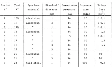
Table 1. Erosion tests with vortex cavitating devices Device N° 1 2 2 3 3 3 3 3 4 4 4 Test N° 13B 14 14B 15 16 17 18 19 20 21 22 Specimen material Aluminium Aluminium II Aluminium II tl II II Aluminium II Mild steel Stand-off distance (mm) 1 2 1 1 1 2 3 5 1 3 1 Downstream pressure (bar) 14 14 14 14 5 14 14 14 14 14 14 Exposure time (min) 10 10 10 10 10 10 10 10 10 10 600 Volume loss (mm ) < 0.1 < 0.1 < 0.1 1.5 < 0.1 1.5 1.5 1 60 10 0.3
Table 2. Erosion resistance of some common materials
Material Density Erosion coefficient Relative resistance
(mg/mm ) (mg min kW ) (basis : aluminium)
Aluminium Plexiglass
Duraluminium (4% Cu) Stainless steel Mild steel (A 37-1)
2.7 1.2 2.8 7.8 7.7 1.0 1.1 6.8 4.6 3.9 X X X X 10 10 10 10 -1 -3 -k 1 9 150 2200 2600
such as those encountered in the dismantling of nuclear power plants. As compared with other types of mechanical erosion like high pressure jets and grit blasting, cavitation erosion has the advantage of not producing solid or liquid aerosols.
pressure did not exceed 60 bar, the most efficient cavitation devices tested achieved measurable erosion rates on hard materials like stainless steel.
Full-scale tests using a nozzle moving over the contaminated surface and a pressure of 300-600 bar may now be envisaged.
2.3. Composition of Contamination Layers and Efficiency of Decontamination Contractor: Kernkraftwerk Lingen GmbH, Lingen, Germany
Contract N°: DE-B-004-D Work Period: January 1981 - October 1983
2.3.1. Objective and Scope
The purpose of this research is the characterization of, on the one hand, the contamination layers formed in long-term reactor operation and, on the other hand, of the residual contamination after the application of aggressive chemical techniques. These investigations are performed on samples taken from the primary circuit of the Lingen reactor (520 MWth Boiling Water Reactor, shut down in 1977 after nine years of operation).
2.3.2. Work Programme: See Ref. 1, Paragraph 2.4.2.
2.3.3. Progress and Results
The research work was completed and the final report is being prepared for publication (Ref. 7).
2.3.3.1. Characteristics of contamination layers
Following the determination of the oxide quantities and Co activity, other nuclides were measured (Table 3).
2.3.3.2. Decontamination tests
In order to achieve complete decontamination of surfaces having been exposed to the primary coolant in water-cooled reactors, removal of the oxides is necessary before dissolving the upper layers of the base material by attack with strong solutions.
The LOMI procedure has been tested for oxide dissolution. When LOMI reagents (LOMI = Low-Oxidation state Metal Ions) are used to dissolve the
Table 3. Activity of oxide layers (Reference date 1.9.1983) 2
(Values are given in Bq/g of oxide and Bq/m of pipe surface)
Nuclide
60_ Co
5 5T 7
Fe 106Ru 137Cs 134Cs Half-life (a) 5.27 2.70 1.01 30.10 2.06 Steam (Bq/g) 2.4xl06 9.5xl03 3.2xl02 1.4xl02 Pipe (Bq/m2) 1.9xl07 7.6xl04 2.5xl03 l.lxlO3 Condensate Pipe (Bq/g) 1.5xl07 3.8xl04 3.9xl02 1.4xl03 2.8x1ο1
(Bq/m2) 1.6xl08 3.9xl05 4.1xl03 1.5xl04 2.9xl02
Primary Water Pipe (Bq/g)
7.9xl08 3.9xl06 1.2xl05 3.7xl04
(Bq/m2) 3.6xl010 1.8xl08 5.6xl06 1.7xl06
to decomposition of the oxides. In the decontamination tests, the bivalent vanadium ion has been applied as a metal ion with a low oxidation level:
3+ 2+ 2+ 3+ Fe + V => Fe + V
If the oxides contain larger quantities of trivalent chrome ions, then the lattice structure of the oxides is only partly destroyed, because chrome-III-ions, which are not reduced, stabilize the lattice structure. In order to destabilize these lattice places, too, the chrome-III-ion in the lattice can be converted into the soluble chrome-VI-ion by oxidation with potassium permanganate (KMnO,).
The main test result is that complete removal of the oxide layers could not be achieved through the LOMI treatment alone. The oxide layer was not completely removed even after three LOMI treatments in steam-pipe sample N° 1. The remaining parts of the oxide layer, however, adhered only loosely to the base material. They could be removed readily by a light mechanical treatment. This behaviour of the oxide layers could be due to
the relatively high Cr 0 contents (15.7% - 18.4%).
The oxide layers were completely removed (condensate pipe sample N°l and steam pipe sample N° 2) only through a subsequent oxidic treatment with potassium permanganate and a further after-treatment with oxalic acid. However, complete removal of the oxide layers was not achieved if the decontamination of the pipe samples was executed in the sequence oxidation
treatment, LOMI-treatment (condensate pipe sample N° 2 and steam pipe sample N° 1).
Therefore, the decontamination of the primary purification pipe sample was carried out according to the treatment cycle LOMI, oxidation, and oxalic acid treatment. Contrarily to the condensate and steam pipe sam-ples, three cycles were needed for complete removal of the oxide layer. This could be due to the thicker oxide layer of the primary purification
2 2 pipe (45.8 g/m ) as compared with the condensate pipe (10.8 g/m ) and the
2
steam pipe (8 g/m ) . The bulk of the activity was removed by the oxalic acid treatment and only a very small part of it was removed by the oxida-tion treatment.
2.3.3.3. Conclusions
Three pipe samples from the primary steam, primary condensate and primary water loops of the Lingen nuclear power station, were examined to determine the activity distribution in the base material (activity depth profile). The following processes are of importance for the presence of radioisotopes in the base material:
- deposit of radioactive corrosion products by the coolant in the corrosion-damaged locations of the base material;
- grain boundary diffusion;
- very low-level activation of the base material.
As the result of the studies on decontamination for unrestricted release, the following procedure is recommended:
- removal of the oxide layer by the LOMI procedure,
- removal of a (base) material layer of determined thickness using a very diluted mixture of nitric acid and hydrochloric acid.
2.4. Vigorous Decontamination Tests of Steel Samples in a Special Test Loop Contractor: Ente Nazionale per l'Energia Elettrica, P.ome, Italy
Contract N°: DE-B-005-I Work Period: October 1980 - September 1983
2.4.1. Objective and Scope
decontaminant, reliability, operational radiation exposure and costs are investigated. Eventually, a system for in-situ decontamination of a reactor component will be designed.
2.4.2. Work Programme: See Ref.l, Paragraph 2.5.2.
2.4.3. Progress and Results
The work has been completed and the final report is being prepared for publication (Ref. 8).
2.4.3.1. Oxide layer investigations
The metallographic and microanalytical characterization of the conta-minated oxide layer on AISI 304 stainless steel of the Garigliano BWR plant has been concluded. The conclusions are summarized below.
The morphology and the thickness of the oxide were found to differ markedly over the surface of the examined component part, but the chemical composition was found to be quite uniform. The oxide corresponds very closely to the nickel-ferrite spinel NiO-Fe 0 , where the Ni and Fe atoms are partly substituted by Mn, Cu and Cr atoms. In particular, the Cu distribution across the oxide can be related to the history of the coolant water, which in turn is strongly influenced by metal composition of the coolant and feed water loops.
Apart from the variations of the minor components, it cannot be stated that a double oxide layer exists; in particular, the inner corrosion layer
which in other nuclear reactors was found generali}7 to be rich in Cr, has
not been detected.
2.4.3.2. Decontamination tests
The decontamination tests have been pursued both in static and in dynamic conditions. About sixty tests were performed in total.
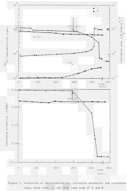
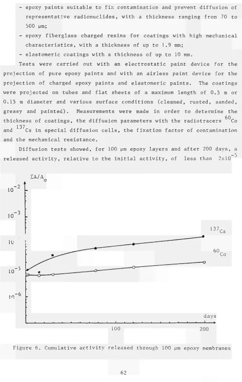
The DECO loop runs carried out in 1983 on AISI 304 specimens coming from the Garigliano BWR are summarized in Table 4. The evolution of decontamination, corrosion potential and corrosion rate with time, in the runs N° 6 to 8 are shown in Figures 1 and 2.
o
CD ω α ο
>> +J
-Ρ υ ra ο ■Η
-Ό ra ί
ο ο
-ρ
c
0) -μ
ο α c ο
■Η
m ο
(Η
tn
ο
U
time (min) 0.50f*
ω
£ 0.35
0.20
0 . 0 5
ν a ■»
•—V·*
0.101
"¿~
150 300 450 600
time (min)
900
[image:22.595.34.528.25.770.2]'fi
Q.
υ
-Ρ
o ra o
■Η
ra
(Η
o o o
CD
τ 10
ι
CM
ε
υ
2 Ci
10 χ
i
cc
10
10
150 300 450 600 time
(min!
a
ω
-p
ra
u c
o
■Η
ω o
U u o o
0.20f
ω
-ρ
c
cl)
■Ρ
o α c o
•Η
M O
U u
o
ü
-0.25
-0.401
150 300 450 600 time (min)
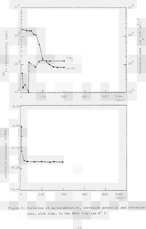
Figure 2. Evolution of decontamination, corrosion potential and corrosion
rate, with time, in the DECO loop run N° 7.
[image:23.595.31.522.31.800.2]Table 4. Conditions and results of dynamic decontamination tests Test N° Decontaminant (vol. %) Temperature (°C) Test time (h) Flow-rate (m/s) Decontamina-tion factor
6
0.35HF +5HN03 40-80 9+51
36707
4.1HC1 40 4.834
26108
0.35HF +5HN03 40 12.504
1.19
0.85HC1 40 11.754
2.5 10 4HC1 +2.5HNO 40 2.104
5750 11 0.75HF +2.5HNO 40-80 5.5+24
2360 * 12 0.75HF +5HN0 42 3.35 1-4 839* With oxygen controlled at less than 50 ppb.
2.4.3.3. Basic considerations about vigorous decontamination
Basic phenomena concerning the corrosion/dissolution of AISI 304 stainless steel were investigated in laboratory tests which have been extensively described in Ref. 9. Many potentiodynamic polarization curves both with stainless steel and platinum electrodes in the examined solutions have been recorded. These curves allowed to explain the strange behaviour of the 4 vol.% HCl + 13 vol.% HNO solution, for which the potential stagnates at typical oxide values and dissolution does not occur.
2.4.3.4. Investigations on decontaminated materials
The characterization of the decontaminated specimens was aimed both at determining the final contamination level and evaluating the condition of the decontaminated surface.
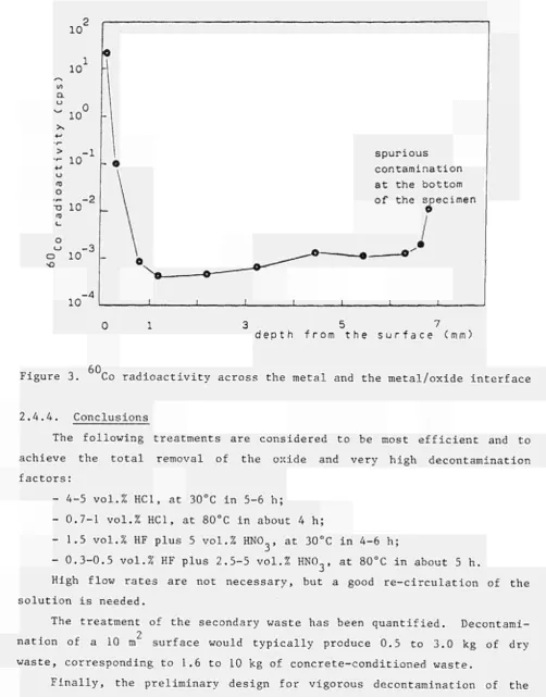
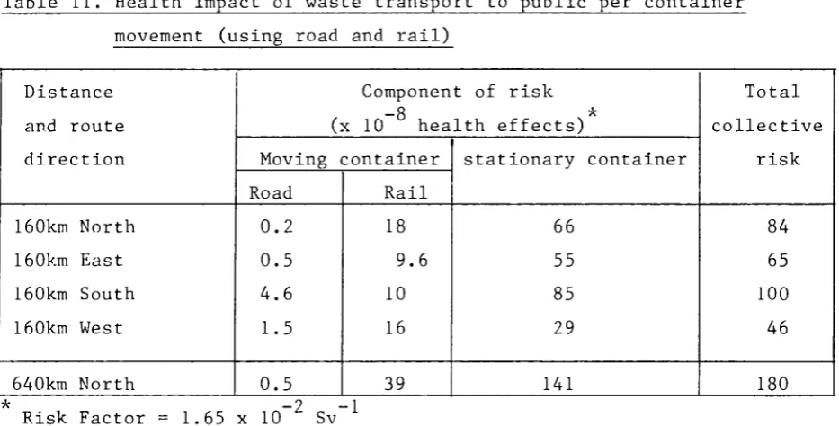
Metal layers were removed and counted, beginning from the face opposed to the contaminated one. The Co radioactivity profile across the metal and the metal oxide interface is given in Figure 3. The data show that the bulk of the metal is not activated and the final surface contamination levels are within the limits for unrestricted release.
Though the metal surfaces are generally very clean and shiny after vigorous decontamination, some differences according to the nature of the
inter-10
10
CL
w 0
10
> - 1 "- 10
+-> u
o
- 2
"Ό 10
Ι Ο
<-> - 3 ο 10 Ι ο
spurious contamination at the bottom of the specimen
1
Ni-10 -4
[image:25.595.43.546.61.703.2]3 5 7 depth from the surface (mm)
Figure 3. Co radioactivity across the metal and the metal/oxide interface
2.4.4. Conclusions
The following treatments are considered to be most efficient and to achieve the total removal of the oxide and very high decontamination factors:
- 4-5 vol.% HCl, at 30°C in 5-6 h;
- 0.7-1 vol.% HCl, at 80°C in about 4 h;
- 1.5 vol.% HF plus 5 vol.% HNO , at 30°C in 4-6 h;
- 0.3-0.5 vol.% HF plus 2.5-5 vol.% HNO at 80°C in about 5 h.
High flow rates are not necessary, but a good re-circulation of the solution is needed.
The treatment of the secondary waste has been quantified. Decontami-2
nation of a 10 m surface would typically produce 0.5 to 3.0 kg of dry waste, corresponding to 1.6 to 10 kg of concrete-conditioned waste.
Finally, the preliminary design for vigorous decontamination of the regenerative heat exchanger of the Garigliano plant has been completed.
2.5. Development of Economical Decontamination Procedures
Contractor: Kernkraftwerk RWE-Bayernwerk GmbH, Gundremmingen, Germany Contract N°: DE-B-006-D Work Period: October 1980 - December 1983
2.5.1. Objective and Scope
The main objective of this research is to identify, develop and assess the most suitable decontamination procedures for decommissioning purposes with particular reference to BWRs. The work involves:
- supplementary contamination measurements, in addition to existing ones, in the KRB-A nuclear power plant (a 237 MWe BWR shutdown in 1977 after 11 years of operation);
- decontamination experiments on samples taken from different areas of the primary circuit of the KRB-A reactor;
- evaluation of the experimental results in respect of both the KRB-A reactor and a 1200 MWe BWR.
2.5.2. Work Programme: See Ref. 1, Paragraph 2.6.2.
2.5.3. Progress and Results
Following the development of a suitable decontamination method based essentially on electropolishing with a 70% phosphoric acid solution, a large-scale application test was performed at the KRB-A Gundremmingen Power Plant (Ref. 10).
In order to reduce the restricted area of the plant before safe enclosure, dismantling of the large quantities of slightly contaminated components in the machine house would be desirable. As the radioactive material arising after decontamination is to be stored in the reactor buil-ding, this material should not exceed 10% of the initial quantity. As a demonstration project, 100 t of selected parts from the primary steam, condensate and feed-water loops were treated. The selected parts were insofar representative for about 75% of the total quantity, as their geometry allows measurements for proving that the unrestricted release
limit (0.37 Bq/cm2 in this case) is observed. About 25% of the material
consists of a small diameter tubing, irregularly shaped components, etc., for which an accepted contamination measurement procedure does not yet exist.
ranged between 10 and 1000 Bq/cm2; surfaces in contact with other contami-nated media, like oil or air, showed contamination levels of less than 10
Bq/cm2. In the demonstration test, 65 t of material were treated by the
electrolytical method; for 35 t of material with loosely adhering contami-nation, current methods like steam cleaning were sufficient to reach the limit for unrestricted release.
The secondary waste from regeneration and treatment of the phosphoric acid was less than 2 wt% of the electrolytically treated parts. Adding small parts, which are not decontaminable economically, and other slightly contaminated items like filters, clothing, plastic covers, after volume reduction by incineration and compression, 8.5 t of low-level radioactive waste were left over for an initial quantity of 100 t.
Extrapolating this result cautiously to the 2000 t inventory of the machine house, the radioactive waste resulting from decontamination would be less than 200 t, not needing any shielding for conditioning and trans-port.
2.6. Development of Gel-based Decontaminants
Contractor: Commissariat à l'Energie Atomique, CEN Saclay, France
Contract N°: DE-B-007-F Work Period: February 1981 - September 1982
2.6.1. Objective and Scope
Existing decontamination techniques employ usually abundant quantities of liquid decontaminant and, consequently, produce large volumes of radioactive effluent. Less decontaminant is required, if the decontaminant is applied by means of a gelatineous carrier substance.
The objective of this research was to develop a decontamination technique using highly effective gel-based decontaminants, which is capable of ensuring:
- a reduction of the time during which personnel is exposed to radia-tion;
- a reduction of the contamination of a component, thereby enabling it to be decontaminated more thoroughly after its transfer to the decontamination bays;
- the decontamination of vertical walls;
- a reduction of the quantity of radioactive effluents resulting from decontamination.
2.6.2. Work Programme: See Ref. 1, Paragraph 2.7.2.
2.6.3. Progress and Results
The final report has been published (Ref. 11).
2.6.4. Conclusions
Glycerophtalic, glycerophosphoric gel, silica gel and diopside were tested as decontaminant carriers. Adherence qualities of the gel-based decontaminating compounds were measured. Viscosities were studied as a function of time, temperature and pH. Samples of stainless steel, mild steel, aluminium, copper and plexiglass have been contaminated in laborato-ry, then comparatively treated by applying gels or by dipping into corres-ponding decontaminant solutions.
This study revealed a range of compounds of gels, which efficiently decontaminate surfaces of various materials contaminated by fission prod-ucts or plutonium.
2.7. Metal Decontamination by Chemical and Electrochemical Methods and by Water Lance
Contractor: Commissariat à l'Energie Atomique, CEN Cadarache, France Contract N°: DE-B-008-F Work Period: January 1981 - December 1983
2.7.1. Objective and Scope
The aim of this research was to develop highly effective methods for the decontamination of steel for decommissioning purposes.
Chemical decontamination methods have been studied with the aim to provide very active scouring baths enabling the contaminated surface to be laid bare, without fears of corrosion damage. In order to limit the concentration of the chemicals employed, the chemical action has been accelerated or amplified by electrolytic action.
Decontamination by high-pressure (700 bars) water lance will also be studied, including the "hardening" of the liquid jet by the addition of solids (salts of low or slow solubility or inert abrasives) and the combi-nation of chemical treatment and water lance.
2.7.3. Progress and Results
All decontamination tests carried out in 1983 used samples from the emergency feed-water piping of the KKI Boiling Water Reactor.
2.7.3.1. Decontamination by high-pressure jet
Samples covered with hematite were sprayed with chemical decontami-nants and subsequently submitted to the high-pressure jet. A pressure of
150 bars is sufficient to reach decontamination factors (DF) of 40. A slight increase in pressure improves the DF by a factor of 1.5 for a target-nozzle distance of 5 cm, and a factor of 2 for a 10 cm distance.
2.7.3.2. Chemical decontamination
The solutions which are most effective at room temperature were compared by combining their action with ultrasonic cleaning (Table 5 ) .
Table 5. Combined action of chemical agents and ultrasonics on BWR samples
Chemical agent (mol/1)
Sulphuric acid (2)
Hydrofluoric acid (2)
Hydrochloric acid (2)
+
Hydrofluoric acid (0.5) Hydrochloric acid (2)
+
Hydrogene peroxide Formic acid (2)
+ Formol (0.1) Temperature (°C) 35 50 30 40 30 Time (h) 1 O 3 1 2 1 2 3 1 2 3 1 2 3 Activity (cps) initial 4300 4675 3740 3927 5610 residual 2180 217 < 5 236 < 5 1870 23 < 5 1246 22 0.5 2180 1750 < 5 D F 1.9 19.8 > 860 19.8 > 935 2 162 > 748 3.1 178 > 785 2.5 3.2 > 112 2
In order of decreasing efficiency these solutions include:
- the hydrogene halides (hydrofluoric acid, hydrochloric acid) alone
or combined with an oxidizer (hydrogene peroxide), - sulphuric acid,
- formic acid in the presence a reducing agent (formol).
When used together with an ultrasonic generator, all these reagents achieved nearly complete cleaning with residual activity levels not exceed-ing 10~1 0 Ci/cm2.
2.7.3.3. Electrolytic decontamination
Electrolytic decontamination is effective in sulphuric or formic acid. The lowest residual activity levels were obtained using a two-step process consisting of electrolytic reduction to embrittle and remove the oxide layer, followed by oxidation to eliminate the final trace of contamination by erosion of base metal (Table 6) . Radiochemical purification of the depleted sulphuric solution is possible using sodium hydroxide at pH 10-11 to precipitate the dissolved iron.
Table 6. Electrochemical decontamination of BWR samples
Chemical agent (mol/1)
Sulphuric acid (2)
Oxalic acid (0.16)
Formic, acid (1)
Electrolytic condition Polarity
-+
+
-+
+-+
+
Time (min) 0 10 20 30 40 0 10 20 30 40 0 10 20 30 40 Activit initial 7,500 7,500 90 65 37 13,657 13,657 8,690 7,957 3,500 10,990 10,990 257 170 1207 (cps)
*
2.8. Delegation of an expert to the US-NRC in relation to the clean-up of the TMI-2 plant
Contractor: Studiecentrum voor Kernenergie/Centre d'Etude de l'Energie Nuc-léaire S.C.K./C.E.N., Mol, Belgium
Contract N°: DE-B-011-B Work Period: June 1983 - December 1983
2.8.1. Objective and Scope
Clean-up of a nuclear power station after an accident which caused dispersion of radioactivity in normally non-active areas, differs from decontamination after normal exploitation. In particular, the quantity and nature of the radionuclides are different, contamination of normally clean areas leads to access problems, and large volumes of gases and liquids are to be disposed of.
Unit 2 of the Three Mile Island nuclear power station at Middletown, Pennsylvania, U.S.A. had undergone such an accident in 1979, and valuable information is produced there about the extent of contamination and the clean-up procedures.
In order to transfer such information to the Community, the contractor assigned an expert for a six-month period (June-December 1983) to the NRC/TMI Program Office which is installed close to the power station and is responsible for review and approval of the clean-up procedures and program-mes submitted by the plant owner and his contractors. This was the second delegation of an expert to TMI-2 performed under the present Community research programme, the first one having taken place in 1980-1981 (Ref. 2, paragraph 2.1).
2.8.2. Summary of Experience Gained
2.8.2.1. Treatment of accident-generated waste water 3
From June 1981 to May 1982, the 2,600 m of high-level waste water in the reactor building sump was decontaminated by use of the so-called "Submerged Demineralizer System" (SDS) consisting of zeolite ion-exchange vessels connected together. The processed water is stored on site and used
for flushing purposes.
United States Nuclear Regulatory Commission.
After that, the SDS was used to process 1,390 m3 of reactor building 3
decontamination water and 111 m of tank decontamination water.
Processing of a total of 2,230 m3 of reactor coolant according to a feed-and-bleed cycle from May 1982 to July 1983 lowered the cesium concen tration in that water from 518 to 16.3 GBq/ m~
1 c.
A total of about 3 χ 10 Bq of Cs and Sr was trapped in 14 zeolite vessels which have been sent to Hanford for vitrification tests.
2.8.2.2. Clean-up of the reactor building and of the auxiliary and fuel handling building
In March 1982 the polar crane, the two upper floors, the refueling canal, the D-rings and missile shields and various bridges, hatches and stairwells were flushed in the framework of the so-called Gross Decontami nation Experiment. Emphasis was put on flushing with water without chemi cals because of the option of using the SDS to process the spent decontami nation water. However, strippable coatings and acid or detergent cleaning were also tested locally.
The results of the Gross Decontamination Experiment were fair. Efficiency of the flushing was limited by use of primitive equipment, poor control of personnel movements causing recontamination, and failure to sequence operations correctly. Dose rates were lowered to the 30-400 mR/h range except on the 305' floor where hot spots of up to 1,300 mR/h were left.
Further dose reduction efforts were attempted, including local decon tamination and shielding of important radiation sources. Steady recontami nation through airborne radioactivity limited the efficiency of these works.
Decontamination efforts were also pursued in the Auxiliary Building, using remotely-operated equipment in some cubicles. Special emphasis was put on the management of the make-up and purification demineralizers, the organic resins of which contain some 600 TBq/m of Cs.
2.8.2.3. Reactor core status
the fuel, the bulk of which was transformed into a rubble bed. The precise distribution of the debris in the various parts of the primary loop and the sludge in the reactor building sump is still unknown, and drastic measures (3,500 ppm of boric acid in reactor coolant water, 2,000 ppm in reactor building decontamination water) are taken to prevent criticality. Radiation levels at contact of the removed lead screws were in the range of 10 -50 R/h gamma and up to 2,000 rad/h beta.
On 25 July 1983, the system was depressurized again. Transition from reducing to oxidizing conditions increased cesium leaching drastically, and after some weeks all benefit from the previous cooling water processing
(see Paragraph 2.8.2.1.) was lost. Radiation fields in the range of 8 - 40 R/h gamma and 300 rad/h beta were measured in the space between the head and the plenum.
Various samples of the deposits on the plenum surface were tested for pyrophoricity; the results showed that the water level could be safely lowered to about 0.3 m below the upper edge of the plenum, allowing "dry" radiation measurements and a new television inspection in good conditions.
The space between the plenum and the rubble bed was mapped using an ultrasonic technique. This technique confirmed the results of the televi-sion inspections, showing many fuel rod stubs protruding from the debris or hanging at the plenum but very few, if any, intact fuel assemblies left at the core periphery.
2.8.2.4. Spent fuel pool refurbishment
The TMI-2 spent fuel pool is divided into two parts: the "A" pool which contains six tanks once used to stage Reactor Building Sump water before treatment in the SDS, and the smaller "B" pool which contains the largest part of the SDS system. Present plans call for restoration of the "A" pool to its pre-accident configuration; it should then be used to store the fuel debris canisters from the defueling operations before shipment to a suitable disposal site.
Refurbishment operations include modifications to the SDS piping, removal of the tank ventilation, removal of radiation shields from above and around the pool, decontamination of the tanks, sealing and removal of the tanks, and pool-liner repairs. Works began in spring 1983, and the removal of the last tank is scheduled for mid 1984.
2.8.2.5. Reactor defueling
The Reactor Building polar crane has been refurbished and tested at no load. Load testing is planned for March 1984.
3. PROJECT N° 3: DISMANTLING TECHNIQUES
For the removal of a nuclear power plant, thick-walled steel compo-nents (e.g. reactor pressure vessel) and reinforced concrete structures
(e.g. reactor shielding) must be dismantled. Here, the radioactivity demands particular requirements such as remote operation, minimum dust formation and air cleaning.
The following techniques are being examined and developed:
- thermal techniques such as plasma-arc and oxygen cutting and cut-ting by laser beam;
- mechanical cutting techniques such as sawing;
- explosive techniques for the dismantling of concrete structures; - cutting of metals by intergranular fissuration.
3.1. Plasma Techniques for Cutting Mineral and Metal Materials Contractor: Ansaldo Meccanico Nucleare, Genoa, Italy
Contract N°: DE-C-002-I Work Period: October 1980 -'December 1983
3.1.1. Objective and Scope
This research relates to plasma-arc and thermal lance cutting techni-ques and its basic aim is to provide more information on the processes, to bring the various cutting techniques more closely into line, from a technical and economic standpoint, with the various possible applications in the dismantling of nuclear power plants, and to improve the safety and reliability of these techniques.
The aforesaid techniques were studied independently of the type of power station in which their use is envisaged; however, where specific examples had to be considered, the contractor, as a licensee for Boiling Water Reactor stations, referred to this type of plant.
3.1.2. Work Programme: See Ref.l, Paragraph 3.2.2.
3.1.3. Progress and Results
During 1983, the tests and analyses related to the plasma torch and the oxygen lance techniques were completed.
3.1.3.1. Plasma Cutting
In 1983, the activity focused on the cutting tests and in particular on the qualitative and quantitative aerosol analyses. On the basis of these analyses, suggestions on how to optimize a cutting process for minimizing the emission of harmful substances were put forward.
The cutting tests were performed in air and underwater (at a depth of 130 mm) with ferritic and austenitic steel.
Suction was secured as follows:
- For the atmospheric cutting, by a stiff smooth pipe connection with the exhaust channel; the chamber was closed; inlet was secured by two channels ending under the tests plate to be cut.
- For the underwater cutting, by a plexiglas bell placed concentri-cally above the plasma torch, placed on its base in the water for capturing all gas bubbles coming up.
The measurement procedures were:
- Electric measurements using an aerodynamic particle sizer for measuring particles from 0.5 pm to 15 um and an electrical aerosol analyser for particles from 0.01 urn to 1.0 urn;
- Gravimetric measurement procedures using a gravicon impactor and a gravicon device.
For both steels, the maximum plate thickness was 150 mm in air and 103 mm underwater.
The aerosol emission decreases sharply if the cutting speed is increased and depends also on the kind of steel. In fact, for cutting thicker plates (100-150 mm) in air, the aerosol emission from ferritic steel is about 300% higher than the emission from austenitic steel.
During underwater cutting, there is a lower emission for ferritic steels, up to about 50 mm thickness, whereas for thicker plates the emission is superior.
The quantity of dust is reduced by a factor 3 (from 28 to 9 g/m for austenitic samples of 20 mm thickness) if argon-hydrogen cutting gas is used instead of argon-nitrogen.
3.1.3.2. Thermal Lance
An operational study was performed to compare the manpower required for dismantling reinforced concrete structures in a nuclear power plant using the thermal lance technique or the blasting technique. The results showed that the thermal lance technique requires about 50% more man-hours than the blasting technique and does not damage the surrounding structures.
3.1.3.3. Analysis of radiological protection and safety aspects
An analysis of the radiological aspects related to the plasma-arc technique was developed, considering the possible use of the plasma torch for cutting metal structures directly inside the vessel or after their removal outside the plant in an ad-hoc facility.
Due to difficulties in handling the instrumentation of the plasma torch apparatus, the results of the tests performed with the plasma torch at the ENEA Casaccia Centre were not significant.
3.2. Diamond-tipped Saws for Cutting Concrete Structures
Contractor: Central Electricity Generating Board, Barnwood, United Kingdom
Contract N°: DE-C-003-UK Work Period: April 1980 - December 1983
3.2.1. Objective and Scope
The objective of this research is to develop a suitable diamond saw capable of cutting away remotely the inner 1 m activated layer of a reinforced concrete biological shield or pre-stressed concrete pressure vessel. Since the dose rates within these structures will be too high to permit manual work for practical periods, the saw must be capable of being remotely controlled and operating reliably for long periods. In addition, the cooling system must be designed to be efficient but produce the minimum practical amount of slurry.
This research concerns all types of nuclear power plants.
3.2.2. Work Programme: See Ref. 1, Paragraph 3.3.2.
3.2.3. Progress and Results
3.2.3.1. Testing and sawing on a horizontal concrete floor
The initial testing of the saw with the 2.5 m blade cutting into a concrete floor, reinforced with 18 mm steel bars culminated with the successful removal of a 600 mm cube. The time required to both saw the cube profile and snap out the block was in the order of 90 minutes.
With the blade sawing through 760 mm of reinforced concrete and 240 mm of sandstone bed rock, thus producing a kerf 1 m deep, the rate of advance through the 18 mm reinforcing steel and concrete was 200 mm/min and through the concrete alone 300 mm/min, the sawing rates being
2 2
12 m /h and 18 m /h, respectively.
In this test, the saw was arranged to produce four kerfs: two parallel kerfs 600 mm apart and 600 mm deep, and subsequently crossing these with two parallel kerfs, also 600 mm apart and 600 mm deep, in order to establish the 600 mm concrete cube profile.
Having established this profile, wedges were evenly spaced over a 600 mm length to snap out the lower face of the cube.
3.2.3.2. Testing and sawing on the vertical face of a wall
The equipment for carrying out the sawing of the wall consisted of a mobile crane with stabilizing outriggers and telescopic boom to which was attached the circular saw supporting frame. Fig. 4 shows the general arrangement of the sawing head. The crane boom was able to position the sawing head in both horizontal and vertical planes and the saw frame was pivotted to allow the frame to position itself parallel to the wall surface resting on the two driving wheels and one castor wheel. The crane and boom were able to exert a force onto the frame, and hence the saw, and the driving wheels then traverse the saw frame along (or down) the wall with the castor wheel trailing.
FORK LIFT BRACKETS CASTOR WHEEL
[image:39.842.123.737.39.493.2]FRAME PIVOT
When sawing horizontally across the wall, the out-of-balance forces caused diversions from a straight path. This was rectified by the addi-tion of counterbalance weights on the saw frame and also adjustment of the castor wheel radius.
The fastest sawing rate was achieved on the final horizontal cut across the wall. A full plunge was carried out in 7 min without stalling the drive or approaching an overload condition. This is equivalent to a
sawing rate of 15 m2/h.
The maximum traverse speed over a distance of 1 m with the sawing disc plunged 1 m deep into the concrete was approximately 160 mm/min.
This is equivalent to 10 m2/h or a kerf 1 m deep and 10 m long every hour.
3.2.3.3. Concrete, cube removal
After the two horizontal and two vertical cuts had been completed to establish the 1 metre cube profile, small wedges were inserted in the upper edge of the cube at equal distances along the 1 metre length. These were evenly tapped in to strain and crack the rear face of the cube. This was not successful and resulted only in spalling the corner edges of the concrete. Larger wedges with broader faces were then used and these were successful in snapping the rear wall of the cube.
With the concrete cube now released, the technique for complete removal from the wall was to withdraw the cube onto a fork life truck and lower it to the ground. The front wall of the cube was drilled and a lifting eye plugged into the cube. A cable attached to the eye and the fork lift truck mast was used to withdraw the cube from the wall until it could be fully supported by the life forks. Unfortunately, restricted access for the truck caused a misalignment of gravity centres between the cube and the truck and the cube fell onto the test area base. The cube split along a place which was identified as a construction joint about 200 mm from the top of the cube.
3.2.4. Conclusion
The objective of this phase of the project was successfully achieved and was also within the programme and cost estimates.
the primary concern of the test team. The rate of sawing and possible improvements in technique and application were secondary to achieving the objective without damage to personnel or equipment.
The sawing rates quoted may not be the best possible. It is be-lieved, however, that whilst the plunge rate achieved was \'ery near to the optimum, the traverse rate could be almost doubled with further develop-ment. The wear rate and life of the saw disc could not be accurately estimated from the work carried out by the saw throughout the testing. At
the end of the testing the blade had performed approximately 100 m2 of
sawing and the diamond tips appeared half worn. In general tip wear is constant throughout its full depth, hence a blade of this type could be
expected to saw in excess of 200 m2, which is three eight-hour shifts,
before re-tipping.
3.3. Plasma-oxygen Cutting of Steel Pressure Vessels Contractor: Salzgitter AG, Salzgitter, Germany
Contract N°: DE-C-004-D Work Period: April 1980 - December 1983
3.3.1. Objective and Scope
The purpose of this research is the development of a technique based on a combination of plasma and oxygen torches, capable of cutting up from the clad side thick sections of low-alloy steel clad with stainless steel, occuring in the pressure vessel of light water reactors.
The work comprises cutting tests on thick (up to 600 mm) inactive specimens, optimization of cutting parameters and off-gas filtering system, and a concept study of dismantling reactor pressure vessels.
3.3.2. Work Programme: See Ref. 1, Paragraph 3.4.2.
3.3.3. Progress and Results
The development of a combined cutting torch which consists of a plasma torch and an oxyacetylene torch has been continued.
3.3.3.1. Characterization of aerosols and testing of filter systems
The objective was to analyse the dust and aerosols and to examine selected filter systems with regard to their dust storage capacity and their degree of separation.
In order to obtain detailed information on the particle size distri-bution of the dust and aerosols arising in the course of thermal cutting, extensive preliminary investigations were carried out on ferritic and austenitic steel plates of 20, 40 and 80 mm thickness. The same tests were then performed using the combined plasma-oxyacetylene torch on thick, clad plates (150, 300 and 600 mm).
The cutting tests, aimed at collecting and analysing the dust from single and combined cutting, were performed in the gravity position and
3
with a suction flow rate of 3000 m /h. The dust and aerosols were collec-ted in the suction line of the test rig both ahead of and behind a filter stage or filter combination. Measurements were taken using the EM 100 dust collecting probe of Sartorius Membranfilter GmbH, and the Electrical Aerosol Size Analyser (EAA 3030) of Thermal Systems Incorporated. These were then evaluated by gravimetric and particle size analysis. The measured dust concentrations allowed the separation degrees of the filter stages and combinations to be determined.
The filter system comprised a bulk material pre-filter, an intermedi-ate box filter, which included a first filter of the EU 7 classification and a second filter of the S class, and a final barrel-type filter with a class S element. The first tests showed that the barrel-type filter used as a pre-filter had inadequate dust storage capacity. Therefore, tests with this filter were abandoned.
The following median values were determined for the particle size distribution during the individual cutting tests:
Cutting process Material Median values of particle size distribution (um)
Plasma Plasma
Oxyacetylene
Austenitic Ferritic Ferritic
Raw gas 0.24 0.13 G.23
Gas filtered 0.13 0.075 0.13
once Pure gas 0.01-0.02 0.01-0.02
The tests showed that the least amount of dust is developed when cutting ferritic steel.
Maximum values of the same level can be explained by the fact that the separation degree of the pre-filters does not depend on particle size. In the pure gas, the particle size distribution has a median value of about 0.1 urn.
At 99.999%, the overall separation degree for the tested filter combinations can be viewed as satisfactory. In contrast to this, service life is not adequate.
3.4. Dismantling of Concrete Structures and Metal Components Using Laser Contractor: FIAT TTG SpA, Torino
Contract N°: DE-C-005-I Work Period: April 1981 - April 1983
3.4.1. Objective and Scope
The aim of this research is to study laser techniques for the follow-ing applications in particular:
- drilling holes in prestressed and ordinary reinforced concrete for placing explosive charges with a view to demolition;
- cutting reinforced concrete structures;
- cutting thin and medium-thick metal components.
The laser cutting technique will be studied independently of the type of nuclear power station in which its use is envisaged; however, where specific examples have to be considered, Pressurized Water Reactor sta-tions and Gas-cooled Reactor stasta-tions will be referred to.
3.4.2. Work Programme: See Ref. 1, Paragraph 3.5.2.
3.4.3. Progress and Results
Until May 1983, the 15 kW carbon dioxide laser was not in working condition. In June, tests were resumed, in particular using 10 kW laser power, the copper needle nozzle of 1.5 mm diameter, and an oxygen assist-ant gas pressure of 7 bars. The following tests were performed in these experimental conditions.
3.4.3.1. Cutting and drilling of concrete
Cutting tests on steel-reinforced concrete were carried out. The average cutting depth obtained was 94 + 14 mm at 0.02 m/min velocity and the maximum cutting depth was 160 mm at 0.01 m/min velocity. The large
standard deviation is mainly due to quality variation of the concrete samples used. The kerfs were regular and 3 to 6 mm wide. Laser cutting of steel-reinforced concrete was easier than cutting of non-reinforced concrete. Furthermore, holes of 6-10 mm diameter and 80 mm depth were drilled, using 1 or 2 impulses of 5 seconds.
In conclusion, cutting of concrete and steel-reinforced concrete poses no problems except for the high dust production. Drilling is possible, but the holes obtained were too small to introduce an explosive charge for dismantling.
3.4.3.2. Cutting of steel
Cutting tests were carried out on three types of specimen, i.e.: - 40 mm thick plates of low carbon mild steel (grade Fe 42 C ) ; - 45 mm thick plates of stainless steel (grade AISI 304);
- 26 mm outer-diameter bundle pipe of Inconel 600, in two superposed rows.
For the stainless steel specimens, the average cutting depth obtained was 35 + 5 mm at 0.2 m/min velocity. For a given power level and cutting rate, the average depth of penetration is 20 to 30% higher in mild steel than in stainless steel.
For the Inconel 600 bundle pipe, the velocity needed to cut was 0.1 m/min and 0.07 m/min for the two pipe rows with offset and vertically alined axis, respectively. The cut was irregular and unclean.
3.4.3.3. Analysis of by-products
Two series of measurements were carried out to characterize laser cutting emission by-products. The first measurement was based on isokine-tics sampling, the second on global weighing. All experiments used the same box containing moving workpieces and having an input hole for the laser beam and an output hole for the suction of cutting by-products.
During the first series of tests, an isokinetics emission sample was taken on the exhaust pipe and the following measurements devices were used: a centrifugal separator, a particle counting system based on optical scattering information, a beta-ray balance to measure differential filter densities, organic vapour and nitrogen oxide analysers. Emission
volume flow was 1350 m3/h and dust mass flow varied from 20-30 g/h for
measurements showed more than 60% of particle number between 0.3 and 0.5 pm. Organic vapour concentrations were less than 0.16 ppm and the nitro-gen oxides emission was less than 2 g/h without any environmental problem.
During the second series of tests, the weight of airborne particles produced during laser cutting of concrete was determined. This determina-tion was based on the difference between the concrete weight variadetermina-tion after cutting and the weight of large particles collected on the walls of the box. For a standard cutting condition (10 kW, 0.02 m/min), the average rate (1850 g/h) was nearly three times higher than the rate measured in earlier experiments. The discrepancy was attributed to the limitations of the first measurement method at large (>5 urn) and small (<0.3 um) particle diameters. In order to better understand by-products of small diameter, which are difficult to filter out, a third experiment was programmed.
3.5. Explosive Demolition Techniques for Concrete Structures
Contractor: Taylor Woodrow Construction Ltd, Southall, United Kingdom Contract N°: DE-C-006-UK Work Period: January 1981 - March 1983
3.5.1. Objective and Scope
The objective of this research is to optimize and assess explosive techniques for the demolition of the radioactive concrete structures of nuclear power plants in respect to safety, radiation protection and costs.
The research is directed mainly at the biological shields of early Magnox reactors and the prestressed concrete pressure vessels (PCPV) of later Magnox and Advanced Gas-cooled Reactors. Relevant structures of other commercial nuclear power plants in the European Community, in particular the PCPVs of French Gas Graphite Reactors and the biological shields of light water reactors, will also be considered.
3.5.2. Work Programme: See Ref. 2, Paragraph 3.6.2.
3.5.3. Progress and Results
3.5.3.1. Cratering tests - single shots
Edge effects (2 tests): Earlier tests had indicated that the size of the models being used might be too small with edge effects influencing the