FULL P
APER
a uniform magnetic response. [ 2a , 3 ] High
coercivity is also essential to ensure that the recorded bits are not easily demagnet-ized, providing stability and integrity in the recorded data. [ 2a , 4 ] Platinum alloys of cobalt
and iron with the L1 0 texture are excellent
candidates for this purpose. This is because crystallographically aligned thin fi lms of these particles have an extremely high out-of-plane magnetic anisotropy, which is ideal for use in high density perpendicular magnetic recording. [ 4c , 5 ] Fabrication of such
fi lms usually requires high temperatures (≈500 °C) and bespoke, high vacuum sput-tering equipment to achieve the L1 0 crystal
structure. These requirements mean that all of the other materials used in the con-struction of hard disks are also able to withstand such treatment, and is both eco-nomically and ecologically expensive. [ 4c , 5 ]
As such, we have turned to biomineraliza-tion to address some of these fi nancial and environmental drawbacks. In biominerali-zation, proteins template the formation of a range of complex, hierarchically ordered materials under mild, aqueous conditions to form inorganic– organic composite tissues. [ 6 ] Naturally occurring biominerals
include calcite in shells, [ 7 ] silica in sponges, [ 8 ] and diatoms, [ 9 ]
hydroxyapatite in teeth and bones, [ 10 ] and magnetic particles in
magnetotactic bacteria. [ 6a , 11 ] Biominerals often have signifi cantly
enhanced properties when compared to their nonbiotemplated counterparts, [ 12 ] including: increased toughness (calcite shells), [ 13 ]
light guiding properties (silica sponge spicules), [ 14 ] or maximized
magnetic moment (magnetite chains in bacteria). [ 15 ]
It was previously shown that Mms6, a biomineralization protein from a magnetotactic bacterium, could be used to form a layer of biotemplated magnetite MNPs on a patterned
Developing Biotemplated Data Storage: Room Temperature
Biomineralization of L1
0
CoPt Magnetic Nanoparticles
Johanna M. Galloway , * Jennifer E. Talbot , Kevin Critchley , Jim J. Miles ,
and Jonathan P. Bramble
L1 0 cobalt platinum can be used to record data at approximately sixfold higher
densities than it is possible to on existing hard disks. Currently, fabricating L1 0
CoPt requires high temperatures (≈500 °C) and expensive equipment. One ecological alternative is to exploit biomolecules that template nanomaterials at ambient temperatures. Here, it is demonstrated that a dual affi nity peptide (DAP) can be used to biotemplate L1 0 CoPt onto a surface at room
tempera-ture from an aqueous solution. One part of the peptide nucleates and controls the growth of CoPt nanoparticles from solution, and the other part binds to SiO 2 . A native silicon oxide surface is functionalized with a high loading of
the DAP using microcontact printing. The DAP biotemplates a monolayer of uniformly sized and shaped nanoparticles when immobilized on the silicon surface. X-ray diffraction shows that the biotemplated nanoparticles have the L1 0 CoPt crystal structure, and magnetic measurements reveal stable,
multi-particle zones of interaction, similar to those seen in perpendicular recording media. This is the fi rst time that the L1 0 phase of CoPt has been formed
without high temperature/vacuum treatment (e.g., annealing or sputtering) and offers a signifi cant advancement toward developing environmentally friendly, biotemplated materials for use in data storage.
DOI: 10.1002/adfm.201501090
Dr. J. M. Galloway, Dr. K. Critchley, Dr. J. P. Bramble School of Physics and Astronomy
University of Leeds Woodhouse Lane Leeds LS2 9JT , UK Dr. J. M. Galloway School of Chemistry Cantock’s Close University of Bristol Bristol BS8 1TS , UK
E-mail: [email protected]
1. Introduction
Historically, the density of data that can be stored on a disk drive has increased in a similar manner to Moore’s law. [ 1 ] This rapid
growth rate has been achieved by developing new materials and systems that are able to store increasingly higher densities of data. Hard disks consist of layers of nanostructured magnetic materials that are able to reliably store bits of information. [ 2 ]
High quality and uniformity are essential to ensure that the mag-netic nano particles (MNPs) used to create recording surfaces can store data with high fi delity (i.e., low error rates). This is because MNPs with a uniform size, shape, and crystal structure have
J. E. Talbot, Prof. J. J. Miles School of Computer Science
University of Manchester Kilburn Building Oxford Road , Manchester M13 9PL , UK Dr. J. P. Bramble
Department of Chemistry Dainton Building, Brook Hill University of Sheffi eld Sheffi eld S3 7HF , UK
The copyright line of this paper was amended 23 June 2015.
This is an open access article under the terms of the Creative Commons Attribution License, which permits use, distribution and reproduction in any medium, provided the original work is properly cited.
FULL P
APER
surface. [ 16 ] More recently, increased coercivity of patterned,
biotemplated magnetite was achieved by doping with cobalt. [ 17 ]
Unfortunately, the magnetic hardness of magnetite (and cobalt-doped magnetite) is not high enough for use as the recording layer in current data storage applications. The high coercivity materials that are used in magnetic data storage are not known to be biomineralized by any organisms in nature. However, peptide sequences that are able to bind and template the forma-tion of non-naturally occurring materials under mild reacforma-tion conditions have been developed. Synthetic biology techniques, such as rational design, computational modeling, and biopan-ning, have been used to fi nd and optimize sequences that are able to bind to and biotemplate the formation of materials such as gold, [ 18 ] silver, [ 19 ] platinum, [ 20 ] platinum alloys, [ 4a , 4b , 19c , 21 ]
pal-ladium, [ 22 ] titania, [ 23 ] and semiconductor nanomaterials. [ 4a , 24 ]
Biopanning allows researchers to explore a vast parameter space of peptide binding motifs during the directed evolution of a library of up to 10 15 different peptide sequences. [ 4b , 18c , 25 ]
Randomly generated peptide sequences are displayed on viral or bacterial hosts, which are incubated with the target material. After stringent washing, the remaining bound peptides are col-lected, amplifi ed, and re-exposed to the target 3–5 times. This allows the researcher to direct the evolution of the library to identify peptide sequences that bind strongly to the target. [ 19c , 26 ]
Previously, a gold and silica binding dual affi nity pep-tide (DAP) was used to pattern nanoparticles [ 27 ] and to form
thin fi lms of electrically conductive gold. [ 28 ] In this work, our
DAP sequence consists of a motif that strongly binds to silica
( HPPMNASHPHMH , biopanned by Eteshola et al.) [ 29 ] and another
that biotemplates CoPt ( KTHEIHSPLLHK, biopanned by Klem
et al.) [ 21a ] connected via a fl exible linker ( GSG), the peptide
design is summarized in Figure S1 (Supporting Information). Originally, the L1 0 CoPt phase was not biotemplated by the
CoPt peptide sequence, but achieved by post-biomineralization annealing at 650 °C, and was not templated as a monolayer on a surface. [ 21a ] The biotemplating system presented here has
been optimized to form a closely packed, uniform, magnetically interacting monolayer of biotemplated L1 0 CoPt MNPs onto
silicon surfaces. This is the fi rst time that L1 0 CoPt (a material
that could be used in high density perpendicular recording) has been formed at room temperature and without using any high temperature processing. As the L1 0 CoPt MNPs are templated
as a monolayer onto a surface, this is far more amenable for use in recording when compared to MNPs biotemplated from a bulk solution. As such, this work offers a signifi cant step toward the development of environmentally friendly, biotem-plated magnetic materials for use in data storage.
2. Results
2.1. Surface Biomineralization
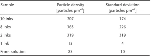
First, the biotemplating system was optimized to maximize the packing density of MNPs biotemplated onto the silicon sur-face. The density of particles templated onto the surfaces was quite low when the silicon substrate was incubated for 1 h in a buffered solution of DAP prior to metallization (Figure S2, Supporting Information, Table 1 , average of 85 ± 10 particles
µm –2 ). These particles are not packed together closely enough
to magnetically interact with each other, so their packing is insuffi cient to allow for the recording of data. In an effort to increase the packing density of MNPs further, silicon was microcontact printed with a poly dimethyl siloxane (PDMS) stamp that had increasing levels of peptide loading ( Figure 1 ). When the stamp is inked and dried once, [ 30 ] the distribution of
particles biotemplated by the DAP onto the silicon surface is inhomogeneous, and there are even fewer particles than seen for the surface functionalized with peptide from solution (just 13 ± 4 particles µm -2 ). It was not possible to quantify the
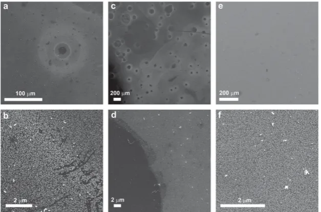
cov-erage of DAP on the surfaces investigated prior to metallization (e.g., using ellipsometry) as the peptide layer does not form a single layer with a consistent fi xed thickness, but instead is unevenly distributed on the surface. This patchy, low coverage is most likely to be due to sparse and inconsistent transfer of the peptide from the stamp to the surface prior to mineralization. Therefore, the consistency and amount of peptide transferred to the surface was improved by increasing the loading of peptide onto the stamp. Figure 2 shows surfaces contacted with stamps that were inked with peptide two, eight, and ten times. In all cases, the stamps were contacted with the surface for 1 min prior to metallization (for detailed methods, see the Supporting Information). When the stamp was inked two times, there was patchy and sparse mineralization (349 ± 319 particles µm –2 ). As
the number of inking rounds increases, so does the packing density of the biotemplated particles. At 8 inks, there is still vari-ability in the density of biomineralized particles on the silicon surface (365 ± 226 particles µm –2 ). When inked with peptide
ten times, a uniform, densely packed monolayer of particles is biotemplated onto the surface (707 ± 174 particles µm –2 ). These
data demonstrate that physical, controlled contact with a stamp bearing a high peptide loading (10 inks) onto the surface is essential to ensuring a uniform densely packed layer of biotem-plated nanoparticles is formed. Therefore, samples for further characterization were all inked 10 times prior to mineralization.
2.2. Imaging and Elemental Analysis of Biotemplated Surfaces
Uniformly sized single domain MNPs are desirable for use in data storage applications, as they exhibit a consistent magnetic behavior. L1 0 CoPt MNPs are thermally stable above a
diam-eter of about 5 nm, and are able to maintain a single magnetic domain up to ≈100 nm diameter. [ 31 ] The 10 inks surface
biotem-plated particles have a narrow size distribution at the lower
Table 1. Particle density measurements and error (1 standard deviation)
as measured from fi ve randomly selected representative images of each sample.
Sample Particle density
[particles µm −2 ]
Standard deviation [particles µm −2 ]
10 inks 707 174
8 inks 365 226
2 inks 319 319
1 ink 13 4
From solution 85 10
[image:2.595.306.549.113.203.2]FULL P
APER
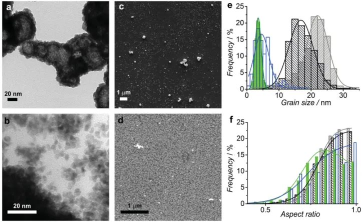
end of this single domain size limit (17 ± 9 nm, Figure 3 and Table 2 ). This means that these surface biotemplated nanopar-ticles are ideally positioned within the lower end of this single domain zone. When the stamp was inked once with the DAP, slightly larger particles with a narrow size distribution were templated (22 ± 8 nm), again within this single domain size
zone. Both of the surface biotemplated examples have far more equidimensional particles (i.e., with an aspect ratio close to 1) than either of the control samples (1 ink = 0.87 ± 0.09 and 10 inks = 0.88 ± 0.08) indicating that the surface immobilized CoPt–DAP is able to exert control over both the size and shape of the particles it templates at room temperature.
As controls, particles biotemplated from a bulk solution, both in the presence of 10 µg mL −1 peptide (bulk DAP) and with no peptide (bulk), have also been analyzed. As expected, non-biotemplated bulk particles have the broadest size (5 ± 5 nm) and shape (aspect ratio 0.84 ± 0.11) distributions. They also form supra-particle clumps, most likely due to their broad grain size distribution, [ 32 ]
which may be hollow spheres. [ 33 ] When the
DAP is present in the bulk solution, there is a shift to a smaller grain size with a narrower distribution (4 ± 2 nm), and the particles are of a more elongated shape (aspect ratio 0.82 ± 0.11). There is also a clear lack of self-assembly into multiparticle structures, which may be due to the narrower size distribution and the coating of peptide which is likely to cap the bulk biotemplated particles.
Energy dispersive X-ray (EDX) spectra and maps were recorded for the 10 ink sample ( Figure 4 ). The maps show that the cobalt and platinum are colocalized in the biotem-plated particles. San et al. found that a 1:1 ratio of Co:Pt in the mineralization solution led to a ≈36:64 ratio in the biotemplated
www.MaterialsViews.com
Figure 1. Schematic to show surface functionalization with biotemplating DAP and metalization with L1 0 CoPt. a) A 1 mg mL −1 peptide solution is
transferred to the stamp and incubated for 1 min before excess is removed via a pipette. b) The stamp is dried and this process repeated 10 times to evenly coat the stamp with a high density of the DAP. c) The stamp is brought into contact with a clean silicon wafer for 1 min, removed, and d) the peptide functionalized silicon is immersed in an anaerobic solution of cobalt and platinum salts under a fl ow of N 2 . The reducing agent (sodium borohydride) is injected after 5 min, e) which metalizes the surface with L1 0 CoPt.
Figure 2. SEM images of samples contacted with stamps inked a,b) 2 times, c,d) 8 times, and
[image:3.595.48.362.452.659.2]FULL P
APER
CoPt MNPs in protein cage biotemplated CoPt. [ 21b ] The ratios
of the reactants (cobalt:platinum:borohydride) were optimized to achieve the 1:1 ratio of L1 0 -structured CoPt in the surface
biotemplated MNPs. An excess of cobalt to platinum ions (3:1) in the mineralization solution allowed the surface immobilized peptide to template CoPt in a 55:45 ratio (Table 2 ), which is very close to the desired 50:50 ratio of L1 0 CoPt. EDX spectra were
also recorded in the transmission electron microscope (TEM) to characterize the elemental composition of the control par-ticles. Quantifi cation of the cobalt and platinum ratio in bulk templated particles showed that, in the absence of peptide, the stoichiometry of the particles refl ects that of the mineralization solution (Co:Pt, 76:24), Figure S3 (Supporting Information) and Table 2 . The peptide templated particles from the bulk solution show a lower proportion of cobalt (Co:Pt, 46:54), which is close to the 50:50 ratio of L1 0 CoPt. Therefore, whether attached to
the surface, or dissolved in the bulk solution, the DAP is able to
control the stoichiometry of the biotemplated nanoparticles to form a desired ≈1:1 ratio of metallic Co to Pt from this aqueous metallization system at room temperature.
2.3. Crystallinity of Biotemplated CoPt
The X-ray diffraction (XRD) spectrum of a clean silicon wafer ( Figure 5 , and Figure S4 and Table S1, Supporting Information) shows peaks for silicon and the native oxide layer on the silicon. The 10 inks sample spectrum shows refl ections that are due to the substrate (silicon and silicon oxide). In addition, there are peaks from the biotemplated nanoparticles, which can be clearly distinguished, and therefore their crystallographic origin can be assigned (Figure 5 and Table S1, Supporting Informa-tion). In L1 0 CoPt, segregation of Co and Pt stacked along the
(001) direction creates a tetragonal distortion, which corre-sponds to the easy axis of magnetization for this material. [ 5c ]
Excitingly, for the 10 inks biotemplated sample, there are peaks at 2 θ = 25.80° and 33.13° that correspond to L1 0 CoPt (001)
and (100) planes, respectively. There is also an indication of a broad peak 2 θ = 40.52° (triangle, Figure 5 ) that best fi ts the CoPt (111) peak. The low coercivity A1 phase of CoPt shows (111), (200), and (220) peaks. [ 5a ] The study of Yu et al. [ 5a ]
demon-strates that annealing at 650 °C is required to achieve (001) and (110) L1 0 peaks in their system, and splitting of the (200) and
(220) peaks is used to confi rm L1 0 phase formation. It is likely
that, if the CoPt (200) peak at 2 θ = 70.12° is present in the 10 inks biotemplated sample, it is obscured by the large Si (400) peak at 2 θ = 69.03° from the silicon substrate. Unfortunately, due to the small peak size from the biotemplated CoPt parti-cles, and position of the Si (400) peak, it was not possible to
www.MaterialsViews.com
Table 2. Summary of grain size, grain shape, and elemental analysis
from EDX measurements for surface biotemplated CoPt nanoparticles (10 inks and 1 ink) and appropriate controls (peptide in bulk and bulk particles). Details of the measurements and the calculation of associ-ated errors are in the Supporting Information. The ratio of Co:Pt is calculated from the EDX spectrum using the EDX analysis software on the respective TEM or SEM.
Sample Grain size [nm]
Error [nm]
Aspect ratio [width/length]
Error Co:Pt ratio from EDX
10 inks 17 9 0.88 0.08 55:45
1 ink 22 8 0.87 0.09 n/a
Peptide in bulk 4 2 0.82 0.11 46:54
[image:4.595.118.481.76.298.2]Bulk 5 5 0.84 0.11 76:24
Figure 3. Representative electron microscopy images of the nanoparticles formed in this study. a) TEM images of bulk precipitated particles which have
[image:4.595.52.292.646.722.2]FULL P
APER
determine if there is a splitting of the (200) and (220) peaks. In heat-treated CoPt fi lms, high intensities of the (001) and (110) peaks when compared to the refl ections due
to A1 ordering (e.g., the (111) peak), indicate a high degree of L1 0 ordering. [ 5a ] In L1 0 FePt,
the absence of the (111) refl ection is used to show that these fi lms are very strongly L1 0
ordered. [ 4c ] Therefore, the higher intensity
of the (001) and (100) peaks in the surface biotemplated samples, when compared to the putative (111) CoPt peak, strongly supports the presence of the L1 0 rather than the A1
phase in the surface biotemplated CoPt. This is the fi rst time that this L1 0 phase has been
formed at room temperature without the need for any subsequent annealing, which is promising for its use in developing biotem-plated data storage.
Bulk precipitated controls both show strong peaks for CoPt 3, which is not the
desired L1 0 CoPt phase. This was
unex-pected, based on the evidence from the EDX spectra discussed above. It may be that, despite the excess of Co 2+ in the mineraliza-tion solumineraliza-tion, CoPt 3 is more likely to form a
crystalline phase under the reaction condi-tions optimized for surface biomineraliza-tion of CoPt. Other cobalt rich phases may form amorphous or poorly crystalline coat-ings on the CoPt 3. This would allow high
levels of cobalt to show up in elemental EDX
analysis, but more platinum rich species to be indicated by the crystallographic XRD data. Interestingly, there is an indication of a Co 3 O 4 phase in the bulk precipitated
parti-cles, which is absent in the peptide bulk tem-plated control. This is most likely to be due to surface oxidation of the non-biotemplated particles. This indicates that the CoPt–DAP remains bound to the particle surface when used in the bulk mineralization solution, offering protection against aerial oxidation. As there are no peaks for CoPt 3 , or oxidized
Co 3 O 4 phases from the surface biotemplated
CoPt nanoparticles, these data support the stability of the L1 0 CoPt surface biotemplated
MNPs against transformation to CoPt 3 ,
or undesired oxidation by exposure to air respectively.
2.4. Magnetic Properties of Biotemplated L1 0 CoPt
Vibrating sample magnetometry (VSM) shows that the surface biotemplated parti-cles have a ferromagnetic hysteresis at room temperature (Figure S5, Supporting Informa-tion). However, the saturation magnetization ( M s ) of the sample, despite being very low (≈3 × 10 −4 emu),
is slightly higher than that estimated based on the volume of
www.MaterialsViews.com
Figure 5. XRD spectra for a 10 inks biotemplated sample and controls. Bulk precipitated
par-ticles (blue) and the peptide bulk templated parpar-ticles (green) show peaks for CoPt 3 , with the peptide appearing to offer protection against surface oxidation of the particles to Co 3 O 4 . The 10 inks biotemplated surface (black) shows silicon and silicon oxide peaks from the substrate, and also shows some CoPt L1 0 refl ections, such as (001) and (100) planes. There is also an indication of a broad peak (triangle) that could be the (111) peak. The silicon substrate (red) shows peaks for silicon and silicon oxide, most likely due to the UV/ozone cleaning treatment. Scans are arbitrarily offset on the vertical scale for clarity, details of peak assignments are shown in Table S1 (Supporting Information).
Figure 4. Representative SEM and EDX maps and spectra of a 10 inks sample, recorded at
FULL P
APER
material on the surface (1.6 × 10 -4 ± 0.4 × 10 -4 emu, calculation
in the Supporting Information VSM Method). This discrepancy may be due to underestimating the amount of material on the surface. Alternatively, the close packing of the biotemplated MNPs on the surface may enhance the magnetic properties of the biotemplated MNPs. [ 34 ] It is probable that our biotemplated
fi lm is not aligned with the C -axis perpendicular to the surface,
so the coercivity of the biotemplated L1 0 CoPt is low, hence the
narrow hysteresis in these bulk measurements.
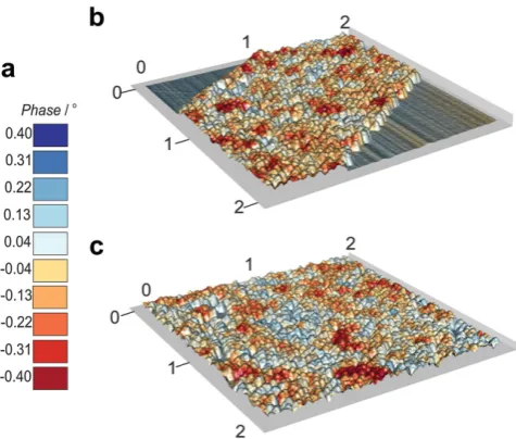
Magnetic force microscopy (MFM) measurements ( Figure 6 and Figures S6–S8, Supporting Information) show signifi cant magnetic contrast of the surface biotemplated L1 0 CoPt MNPs.
Scans were performed over areas that were scored to demon-strate the contrast between the silicon subdemon-strate and the surface biotemplated MNPs. The magnetic interactions between the tip and the surface were recorded at a lift height above the height of the particles to ensure that artefacts due to physical contact between the tip and the surface in non-contact mode are mini-mized. In Figure 6 b, no magnetic contrast can be seen in the phase information recorded over the silicon substrate. When the biotemplated particles are scanned, there are signifi cant positive and negative phase shifts recorded, which correspond respectively to magnetic repulsion and attraction between the tip and the surface.
To conclusively demonstrate that the magnetic interac-tions are solely due to the magnetic interaction of the particles with the tip, the direction of magnetization of the tip should be reversed and the same area scanned. If this were possible,
the sign of the phase shifts should be reversed when the tip magnetization is reversed. Unfortunately, it was not possible to scan an area, reverse the magnetization of the tip, and then rescan the same area. This is because reversing the magnetiza-tion of the tip required removing the tip from the piezo head on the microscope. When the tip was re-mounted, it was not pos-sible to reliably locate the same area to scan again. Figure S6 (Supporting Information) shows sequential MFM scans of the same area, with 90° rotation between them. These plots dem-onstrate that the areas of magnetic attraction and repulsion have the same shapes, sizes, and magnitudes of interaction in successive scans in different scan directions, making them unlikely to be due to artefacts.
3. Discussion
3.1. Size and Shape Control of Surface Immobilized CoPt–DAP
This work reports the formation of biotemplated L1 0 CoPt on
a surface at room temperature for the fi rst time. This material has the potential to be used in high density data storage, and the L1 0 phase has not been formed without the need for
post-biotemplating high temperature processing before. [ 4a , 35 ] These
data demonstrate that, when there is a high loading of the CoPt– DAP on the stamp, the peptide is able to biotemplate a con-sistent layer of densely packed particles onto the stamped silicon surface. It is likely that more peptide is functionalized onto the surface by microcontact printing for the 10 inks sample than for the 1 ink sample. This would lead to more particle nucleation sites being more closely packed together on the substrates with higher peptide loadings. This close packing would also provide less room for maturation, creating smaller, more closely packed biotemplated particles on the 10 inks surface. This would explain the higher density of smaller particles that are observed on the 10 inks surface when compared to the samples that had less inking. These grain size data also show that, when densely packed on the surface, the peptide is able to exert signifi cant control over the size and shape distribution of the nanocles biotemplated on the surface, when compared to the parti-cles templated in the bulk solution. Close packing of the peptide on the solid surface may stabilize the biotemplating action of the DAP, allowing it to biotemplate uniform, equidimensional particles (Figure 3 c,d). The particle size and distribution of the surface biotemplated nanoparticles (17 ± 9 nm) is above the superparamagnetic (SP) size limit for L1 0 CoPt (≈5 nm), [ 36 ]
which is promising for use in data storage applications.
When the peptide was used in the bulk mineralization solution as a control, the elongation of the particles that are observed may be due to the lack of a surface to stabilize the biotemplating peptide during metallization, as well as the presence of the SiO 2 binding portion of the DAP. Display of
repeats of biotemplating peptides on viral coats causes close packing of the peptides, and is thought to stabilize and enhance the biomineralization action and crystallographic alignment capabilities of semiconductor biotemplating peptides. [ 4a ] It is
likely that surface immobilization of the DAP creates a sim-ilar close packing of the CoPt biotemplating peptide on the surface, which may have similar stabilization effects on the
[image:6.595.52.290.74.276.2]www.MaterialsViews.com
Figure 6. Representative MFM composite plots of biotemplated L1 0
FULL P
APER
biotemplating ability of the peptide. The majority of the SiO 2
binding portion of the DAP is probably not interacting with the mineralization solution when it is immobilized onto a surface, as it is this section that should be in contact with the substrate rather than the metallization solution. However, the whole DAP sequence should be able to interact with the miner-alization solution in the formation of the bulk peptide control. Also, the biotemplating peptide is only able to interact with the underside of the growing MNPs when immobilized onto the surface. In a bulk solution, the biotemplating peptide is able to surround all sides of a growing particle, and cap growth in all directions. On a surface, the potential to limit growth is dimin-ished, as the peptide can only bind to facets on the bottom of the growing particle. Therefore, the peptide is porbably only able to control the initial nucleation and growth of the MNPs on the surface by binding to the underside of the nucleating MNPs. Any subsequent growth of the MNPs on the surface is likely to be crystallographically aligned with the nucleated and growing MNP, but this growth cannot be capped by the pep-tide binding to the sides or top of the growing MNP. Similar enhancement of particle size can be seen in a completely dif-ferent mineralization system: magnetite and cobalt doped mag-netite MNP growth on surfaces biotemplated by the biominer-alization protein Mms6. [ 16,17 ] This difference in which parts of
the sequence are able to interact with the metallizing solution during nanoparticle formation could lead to the observed dif-ferences in particle morphology and size between the surface immobilized and bulk solution peptide templated MNPs.
3.2. Crystallographic Evidence for L1 0 CoPt Formed at Room Temperature
The crystallinity data shows that the DAP is able to biotemplate the L1 0 phase, rather than the lower energy A1 phase, or CoPt 3 ,
which forms from the bulk solution at room temperature. The surface immobilized biotemplating peptide is probably able to lower the activation energy of the formation of the L1 0 CoPt
phase from aqueous solution, thus favoring the formation of the higher energy L1 0 phase. Mao et al. [ 4a ] propose that close
packing of biotemplating peptides (in their case on a viral coat protein) enhances the biotemplating function of their miner-alization peptides and allows for crystallographic alignment of the biotemplated nanoparticles. The close packing of the DAP on the silicon surface may enhance the crystallographic align-ment and templating capabilities of our biotemplating peptide. As discussed above (Section 3.1), the peptide is likely to only be able to bind to the underside of the MNPs. This means that capping of the peptide cannot be responsible for preventing oxi-dation of the surface biotemplated MNPs. A similar resistance to oxidation has been observed in magnetite biotemplated on surfaces by the Mms6 protein in previous work. [ 16,17 ] It is
pos-sible that the high quality of the biotemplated L1 0 CoPt MNPs
is able to form outer faces that are able to resist oxidative attack, and thus be stable against alteration by air.
Recent work has shown that the binding of biotemplating peptides to specifi c facets of platinum is crucial for these peptides to control the shape of the Pt nanoparticles that are formed. [ 20a , 20b , 20d ] It is reasonable to assume that similar specifi c
binding of the biopanned CoPt sequence ( KTHEIHSPLLHK ) [ 21a ] to a
distinct L1 0 CoPt facet is able to direct the growth of this highly
ordered phase. The CoPt biotemplating peptide may also be able to bind ions and/or prenucleation clusters of cobalt and platinum, organize them into the tetragonal L1 0 structure and
facilitate their reduction to metallic CoPt when bound to the surface. The peptide may also be able to do this in the bulk solution, but a larger excess of cobalt, or other alterations to the reaction conditions (which are optimized for surface minerali-zation), may be necessary for this to occur. It should be possible to probe the interactions of biomolecules, such as the DAP, with specifi c L1 0 CoPt surfaces (e.g., (100), (110) or (220)), and
to compare this to binding to A1 CoPt surfaces. Computational modelling of the peptides interacting with the bimetallic L1 0
CoPt surfaces could be employed to elucidate which peptides in the sequence are important for binding to specifi c facets, in a similar manner to computational studies that have explored biotemplating peptide binding to specifi c monometallic gold [ 37 ]
and platinum [ 20d ] surfaces. These studies have been used to
gain great insight into the mechanisms and specifi city of mate-rials binding by these gold and platinum biotemplating pep-tides, and similar techniques could be used to study how and where biotemplating peptides bind to L1 0 CoPt to template its
growth.
3.3. Magnetic Properties of Surface Biotemplated L1 0 CoPt
The nanoscale magnetic behavior of the surface biotemplated MNPs is complex, with different sizes and shapes of zones of repulsion and attraction that extend over multiple particles. Interestingly, the shape, size, and position of the multiparticle magnetic zones appear to be stable at room temperature. Such patterns arise naturally from the demagnetization of magnetic thin fi lms. The size and shape of clusters that have similar magnetization depend upon the magnetostatic and exchange interactions between particles. [ 34 ] In 2D assemblies, these
inter-actions, and the resulting cluster size, are very strongly deter-mined by the particle size and spacing. [ 38 ] This observation of
nanoscale regions with stable perpendicular magnetization is promising for the use of biotemplated CoPt in magnetic data storage, as a bit of information is usually recorded across a number of particles. [ 2 ] Thus, this ability of these surface
biotemplated L1 0 CoPt MNPs to stably maintain their magnetic
orientation at room temperature indicates that they could be developed for use in magnetic data storage applications.
Electron holography and Fresnel–Lorentz microscopy has been used to image multiparticle magnetic domains in closely packed layers of magnetite nanoparticles. [ 39 ] They found that
the shape of the multiparticle domains that formed in the mag-netite MNP assemblies is strongly dependent on the macro-scopic shape of that assembly. [ 39 ] In previous work with
ferri-magnetic magnetite and cobalt-doped magnetite biotemplated onto surfaces, alignment and elongation of multiparticle zones of magnetic attraction and repulsion parallel to the long axis of the assembly can be observed using MFM. [ 16,17 ] For the
sur-face templated L1 0 CoPt MNPs presented in this work, the
multiparticle zones do not appear to align signifi cantly with the edges of the scored areas (Figure 6 b and Figure S6, Supporting
FULL P
APER
Information). This could be due to the lack of c -axis alignment that is inferred from the XRD and VSM measurements. It may also be that nanoscale interactions between neighbors of parti-cles with random crystallographic orientation are dominating over any shape anisotropy exerted by the microscale scored boundaries. This would lead to the shape and size of the mul-tiparticle zone system being dependent on slight variations in fi lm heterogeneity (e.g., particle packing and spacing) rather than on any microscale shape features.
In sputtered or annealed fi lms, out-of-plane c -axis alignment ensures high perpendicular magnetic anisotropy, making these layers suitable for recording. [ 4c , 5 , 40 ] In fi lms with out-of-plane c -axis alignment, the (001), (110), (200), and (220) peaks are observed in XRD. [ 4c , 5a , 5b ] Our biotemplated fi lm shows L1
0 CoPt
(001), (100), (101), and (002) refl ections (the (200) and (220) peaks may be obscured, see Section 2.3 above). This indicates that our biotemplated L1 0 CoPt MNPs are not aligned in the
same orientation as the sputtered fi lms (e.g., there is no (110) refl ection). This different alignment may explain why there is not a measureable coercivity for the surface biotemplated MNPs when measured in VSM. Hysteresis loops of sputtered CoPt with misaligned grains can show loops with reduced [ 41 ]
or no [ 42 ] coercivity depending on the direction in which the
external fi eld is applied. As it was only possible to measure the magnetization of the samples in the out-of-plane direction, it may be that the C -axis of the fi lm is aligned in plane, or in some
other orientation.
Greater understanding of the facet specifi city of a range of biotemplating peptides for L1 0 CoPt (discussed above), could
allow the development of peptides that are able to perpendic-ularly align the c -axis, e.g., by binding to the (110) plane, and create high coercivity biotemplated L1 0 CoPt. Klem et al. [ 21a ]
found the CoPt templating section of the DAP by biopanning, but were unable to fully achieve the L1 0 CoPt phase without
annealing the biotemplated particles. They displayed the pep-tide sequence within a heat-shock protein cage, which could act as a barrier to diffusion of the reactants to the biotemplating sequence on the interior. They also performed their minerali-zation at 60 °C. Both of which may reduce the biotemplating control of the CoPt sequence when compared to its display and mineralization at room temperature on a silicon surface. It may also be that the CoPt sequence is much more closely packed when displayed on a silicon surface. The cross-sectional area of the hydrated DAP should be about 2 nm by 3 nm. If the 10 inks surface is coated with a monolayer of the DAP, there would be ≈40 CoPt templating sequences that would be available to bind to the underside of each 17 nm diameter particle. The protein cage displays a much lower density of the CoPt tem-plating sequence (24 repeats of the peptide per particle). It is also possible that the conformation of the CoPt sequence may be more conducive to templating L1 0 CoPt when immobilized
onto a silicon surface when compared to display within a pro-tein cage, as the rigidity of the silicon support, or the proximity of the SiO 2 binding domain, may enhance the biotemplating
function of the CoPt sequence. Any one, or a combination of these reasons, may explain why the DAP is able to biotemplate L1 0 CoPt at room temperature without annealing on a silicon
surface, but needs annealing to do this when a protein cage is used as the biotemplate.
It may be possible to anneal our biotemplated fi lms, as was done to achieve the L1 0 phase in previous work, [ 4a , 4b , 21a , 43 ] which
may align the c -axis of the biotemplated MNPs out-of-plane. However, annealing often leads to agglomeration of adjacent particles, which can signifi cantly increase particle sizes and size distributions, and thus introduce undesirable heteroge-neity. Also, annealing a biotemplated fi lm removes many of the advantages of the biotemplating process (e.g., low temperature, low energy, and low cost). Therefore, we propose a number of heat-free ways that these L1 0 CoPt fi lms could be improved for
use in magnetic data storage, which are explored in the Conclu-sions section below.
4. Conclusions
This work demonstrates that L1 0 CoPt can be formed on a
sur-face at room temperature using a peptide biotemplate for the fi rst time. The biotemplating peptide affords excellent control over the size and shape of the MNPs formed when immobi-lized onto a surface, and our surface biotemplated L1 0 CoPt
are above the SP size limit for L1 0 CoPt. The MFM data clearly
shows that the surface biotemplated MNPs form multipar-ticle zones of magnetic interactions which are stable at room temperature. This stability is promising for the use of these biotemplated surfaces to develop biotemplated magnetic data storage. We believe that, in tuning the particle packing density by a controlled increase in the peptide loading to the surface, it should be possible to tailor the size of the surface biotem-plated particles. Although the sputtered L1 0 platinum alloy
fi lms do show extremely high coercivity, [ 4c , 5b ] a number of the
sputtered particles are below the SP size limit. These smaller particles are not able to maintain their magnetic orientation at room temperature in the absence of an applied fi eld, so it is very easy to switch their direction of magnetization. These het-erogeneities can act as nucleation points for demagnetization in recording layers, leading to loss of data (i.e., poor integrity), especially in the smaller bit sizes required in high density data storage. [ 2a , 4d ] Therefore, biotemplated systems such as that
pre-sented here may offer not only a more environmentally friendly and cheaper alternative to conventional hard-disk data storage, but also one that is able to overcome this size control limitation seen in sputtered thin fi lms of L1 0 CoPt.
Unfortunately, the L1 0 CoPt MNPs biotemplated onto our
surfaces did not have a high out-of-plane coercivity, which prob-ably due to a lack of alignment of the c - axis of the biotemplated MNPs based on our crystallographic data. Computational modelling of peptide interactions with surfaces could signifi -cantly increase our understanding of how and where specifi c peptides bind to different L1 0 CoPt facets. This may even be
able to identify peptides that are able to bind to key facets, as has been done for platinum [ 20a , 20b , 20d ] and gold, [ 18a , 37 ] and thus
may be able to perpendicularly align the c -axis of L1 0 CoPt for
high density recording. Soft magnetic underlayers (e.g., ruthe-nium) are used to enhance the out-of-plane anisotropy of plat-inum alloy fi lms. [ 2a ] A biotemplating DAP could be designed
to biotemplate this layer too. In sequence, these DAPs could be used to build a biotemplated magnetic thin fi lm stack that incorporates such underlayers, all from aqueous solutions at
FULL P
APER
room temperature. Such layering may signifi cantly enhance the out-of-plane coercivity of the biotemplated magnetic thin fi lm, which would allow it to be used for recording.
It is our goal to demonstrate that materials templating pep-tides have the ability to form the components necessary to build devices, such as hard disks, without the need for high cost, high temperature, and high energy processing. In developing peptide templated magnetic data storage, it may be necessary to combine a range of different biotemplated materials. There is a vast array of biosystems that can be adapted for use in industry, and in the development of future consumer products. [ 6d ] The
ultimate step toward making bioinspired devices a reality is to combine separate biotemplated components to build con-sumer devices. Researchers have begun to demonstrate that biotemplated and bioinspired components; such as solar cells, [ 44 ] circuitry, [ 28 ] data storage (this work), fi bre optics, [ 14 ]
and optical displays; [ 45 ] can be built. Research focussed on the
improvement of the effi ciency of such pioneering results and the combination of bioinspired and biotemplated components could be used to construct environmentally friendly devices. For example, biotemplated multilayers for hard disk recording could be combined with bioinspired solar cells, circuitry, fi ber optics, and optical displays to build biokleptic smartphones or computers under far milder conditions than are used in con-ventional materials synthesis. We feel that this work on devel-oping biotemplated materials for magnetic data storage (and work that will develop from it) is integral to making a greener, bioinspired future a reality.
5. Experimental Section
Substrate Preparation: 1 cm 2 sections of silicon wafer were rinsed with propanol, soaked in ethanol (1 h), dried with N 2 , and then treated with UV/ozone for 20 min (UVOCS). PDMS (Sylguard 184 base plus 10% (w/w) curing agent) was mixed and degassed, poured over the silicon master and cured (60 °C and 16 h). Cured stamps were soaked in ethanol (20 min) and treated with UV/ozone (20 min). The stamp was inked with 1 mg mL −1 CoPt–DAP solution (Ac- HPPMNASHPHMH-GSG -KTHEIHSPLLHK -Am (GensScript), >95% purity, N- terminal acetylation,
c -terminal amidation) in phosphate buffered saline (PBS (Invitrogen): 10 × 10 −3 M sodium phosphate, 2.68 × 10 −3 M KCl, 140 × 10 −3 M NaCl, and pH 7.4). After 1 min, excess peptide solution was removed and the stamp gently dried with N 2. Inking and drying was repeated <10 times before the stamp was contacted onto silicon (cleaned as for the master above). After 1 min, the stamp was removed, and the substrate transferred to a glass reaction vessel (see Figure 1 ).
Mineralization: Solutions of cobalt (Co 2+ , 30 × 10 −3 M CoSO 4 ·7H 2 O) and platinum (Pt 2+ , 10 × 10 −3
M Na 2 PtCl 4) salts, and a reducing agent (sodium borohydride, 25 × 10 −3 M NaBH 4) were prepared in deoxygenated Milli-Q water (vacuum degassed for >1 h and N 2 sparged for >1 h). 2.5 mL Co 2+ and 2.5 mL Pt 2+ were added to a reaction vessel. For the bulk peptide control, 100 µL of a 1 mg mL −1 peptide solution (10 µg mL −1 in the 10 mL reaction) in PBS was added to the metal salts in the reaction vessel in place of the peptide incubated substrate. N 2 was bubbled through the solution in the reaction vessel, and after 5 min, 5.0 mL of NaBH 4 was injected. After 45 min, biotemplated surfaces were rinsed 3–5 times in deoxygenated water and dried with N 2 .
Electron Microscopy: A Hitachi SU8230 cold fi eld emission scanning electron microscope (SEM) was used to image samples at 2–10 keV via the in lens SE (U) detector. EDX spectra were recorded with an Oxford Instruments AZtecEnergy EDX system at 5 keV in the SEM. Transmission electron microscopy (TEM) images were taken using a Phillips CM200
(FEG) TEM at 200 keV, using the digital micrograph software. EDX spectra were recorded using an Oxford Instruments INCA EDX system and a Gatan Imaging Filter on the TEM. Particle density was calculated by averaging the number of particles per unit area in fi ve different representative images for each sample. For grain sizing, the length and width of ≈400 particles per sample was measured using Image J. [ 46 ]
X-Ray Diffraction (XRD): Spectra were recorded using a Brucker-AXS D8 series2 diffractometer, set to a Bragg Brentano Parafocussing Geometry. X-rays were generated at room temperature using a Cu Kα source at 40 kV. Monochromated X-rays pass through a 2 mm exit slit and an automatic divergence slit of 0.2°. Diffraction intensity was collected at 2 θ between 10° and 80° on a Braun position sensitive detector (0.01° and 7.5 s step −1 ). These data were processed using AXS Commander and EVA software.
Vibrating Sample Magnetometry (VSM): Hysteresis loops for the biotemplated surfaces were measured perpendicular to the surface with an Oxford Instruments Maglab VSM, using an applied fi eld of −10 to 10 kOe at 295 K.
Magnetic Force Microscopy (MFM): Plots were recorded using magnetized Cr/Co coated MESP MFM probes (Brucker) on a Multimode Nanoscope III. The topography was recorded in tapping mode, and was followed at a lift height of 25–50 nm to avoid tip impacts when measuring magnetic interactions in non-contact mode (Figure S9, Supporting Information). These data were processed using WSxM, [ 47 ] and 3D plots generated in “R” using the rgl package.
Supporting Information
Supporting Information is available from the Wiley Online Library or from the author.
Acknowledgements
The authors would like to thank the University of Leeds and an EPSRC Doctoral Prize Fellowship (Grant No. EP/K503017/1) for supporting J.M.G. during this work. They would also like to thank the following people at the University of Leeds: Lesley Neve (XRD), Dr. Oscar Céspedes (VSM), Stuart Micklethwaite and John Harrington (SEM and EDX), Dr. Mike Ward (TEM and EDX), Prof. Steve Evans (discussion), and Prof. Richard Bushby (discussion). The authors also would like to acknowledge and thank Dr. Marcin Górzny and Jeanette Maggs for their excellent design input into cover art suggestions. We would also like to thank Dr. Andrea Rawlings (discussion), Dr. Sarah Staniland (discussion), and Scott Bird (discussion) at The University of Sheffi eld, Prof. Thomas Thomson (discussion) at The University of Manchester, and Beatrice Martinelli (discussion).
Received: March 18, 2015 Revised: May 14, 2015 Published online: June 15, 2015
[1] W. Arden , M. Brillouët , P. Cogez , M. Graef , B. Huizing , R. Mahnkopf , J. Pelka , J.-U. Pfeiffer , A. Rouzaud , M. Tartagni , C. V. Hoof , J. Wagner ,
Towards a “More-than-Moore” Roadmap , Report from the CATRENE Scientifi c Committee , Paris, FR 2011 pp. 131 .
[2] a) S. J. Lister , T. Thomson , J. Kohlbrecher , K. Takano , V. Venkataramana , S. J. Ray , M. P. Wismayer , M. A. de Vries , H. Do , Y. Ikeda , S. L. Lee , Appl. Phys. Lett. 2010 , 97 , 112503 ; b) O. Hellwig , A. Berger , T. Thomson , E. Dobisz , Z. Z. Bandic , H. Yang , D. S. Kercher , E. E. Fullerton , Appl. Phys. Lett. 2007 , 90 , 162516 ; c) T. R. Albrecht , H. Arora , V. Ayanoor-Vitikkate , J. Beaujour , D. Bedau , D. Berman , A. L. Bogdanov , Y. Chapuis , J. Cushen , E. E. Dobisz , G. Doerk , H. Gao , M. Grobis , B. Gurney , W. Hanson ,
FULL P
APER
www.MaterialsViews.com
O. Hellwig , T. Hirano , P. Jubert , D. Kercher , J. Lille , Z. Liu , C. M. Mate , Y. Obukhov , K. C. Patel , K. Rubin , R. Ruiz , M. Schabes , L. Wan , D. Weller , T. Wu , E. Yang , IEEE Trans. Magn. , 2015 , 51 , 1 . [3] a) Q. A. Pankhurst , J. Connolly , S. K. Jones , J. Dobson , Phys. D:
Appl. Phys. 2003 , 36 , R167 ; b) S. Staniland , W. Williams , N. Telling , G. Van Der Laan , A. Harrison , B. Ward , Nat. Nanotechnol. 2008 , 3 , 158 .
[4] a) C. Mao , D. J. Solis , B. D. Reiss , S. T. Kottmann , R. Y. Sweeney , A. Hayhurst , G. Georgiou , B. Iverson , A. M. Belcher , Science 2004 ,
303 , 213 ; b) B. D. Reiss , C. Mao , D. J. Solis , K. S. Ryan , T. Thomson , A. M. Belcher , Nano Lett. 2004 , 4 , 1127 ; c) L. Zhang , Y. K. Takahashi , K. Hono , B. C. Stipe , J.-Y. Juang , M. Grobis , J. Appl. Phys. 2011 , 109 , 07B703 ; d) T. Thomson , G. Hu , B. D. Terris , Phys. Rev. Lett. 2006 ,
96 , 257204 .
[5] a) L. N. Yu , L. Y. Lu , Z. D. Xu , X. G. Xu , J. Miao , Y. Jiang , Mater. Lett. 2012 , 86 , 142 ; b) O. Mosendz , S. Pisana , J. W. Reiner , B. Stipe , D. Weller , J. Appl. Phys. 2012 , 111 , 07B729 ; c) S. Balaji , S. Amirthapandian , B. K. Panigrahi , S. Kalavathi , A. Gupta , K. G. M. Nair , J. Phys. Condens. Matter 2007 , 19 , 356211 .
[6] a) A. Arakaki , H. Nakazawa , M. Nemoto , T. Mori , T. Matsunaga ,
J. R. Soc., Interface 2008 , 5 , 977 ; b) S. Mann , Biomineralization: Principals and Concepts in Bioinorganic Materials Chemistry , Oxford University Press , Oxford, UK 2001 , pp 198 ; c) F. Nudelman , N. A. J. M. Sommerdijk , Angew. Chem. 2012 , 124 , 6686 ; Angew. Chem. Int. Ed. 2012 , 51 , 6582 ; d) J. M. Galloway , J. P. Bramble , S. S. Staniland , Chem. Eur. J. 2013 , 19 , 8710 ; e) J. M. Galloway , S. S. Staniland , J. Mater. Chem. 2012 , 22 , 12423 .
[7] a) F. C. Meldrum , H. Cö lfen , Chem. Rev. 2008 , 108 , 4332 ; b) N. Leonardos , B. Read , B. Thake , J. R. Young , J. Phycol. 2009 , 45 , 1046 .
[8] J. C. Weaver , G. W. Milliron , P. Allen , A. Miserez , A. Rawal , J. Garay , P. J. Thurner , J. Seto , B. Mayzel , L. J. Friesen , B. F. Chmelka , P. Fratzl , J. Aizenberg , Y. Dauphin , D. Kisailus , D. E. Morse , J.
Adhe-sion 2010 , 86 , 72 .
[9] a) M. Hildebrand , Chem. Rev. 2008 , 108 , 4855 ; b) L. Senior , M. P. Crump , C. Williams , P. J. Booth , S. Mann , A. Periman , P. Curnow , J. Mater. Chem. B 2015 , 3 , 2607 .
[10] G. E. Fantner , O. Rabinovych , G. Schitter , P. Thurner , J. H. Kindt , M. M. Finch , J. C. Weaver , L. S. Golde , D. E. Morse , E. A. Lipman , I. W. Rangelow , P. K. Hansma , Compos. Sci. Technol. 2006 , 66 , 1205 . [11] a) C. T. Lefèvre , D. A. Bazylinski , Microbiol. Mol. Biol. Rev. 2013 ,
77 , 497 ; b) T. Prozorov , D. A. Bazylinski , S. K. Mallapragada , R. Prozorov , Mat. Sci. Eng. R. 2013 , 74 , 133 ; c) A. E. Rawlings , J. P. Bramble , R. Walker , J. Bain , J. M. Galloway , S. S. Staniland ,
Proc. Natl. Acad. Sci. U.S.A. 2014 , 111 , 16094 . [12] L. Addadi , S. Weiner , Phys. Scr. 2014 , 89 , 098003 .
[13] Y.-Y. Kim , L. Ribeiro , F. Maillot , O. Ward , S. J. Eichhorn , F. C. Meldrum , Adv. Mater. 2010 , 22 , 2082 .
[14] J. Aizenberg , V. C. Sundar , A. D. Yablon , J. C. Weaver , G. Chen , Proc. Natl. Acad. Sci. U.S.A. 2004 , 101 , 3358 .
[15] A. Muxworthy , Astron. Geophys. 2013 , 54 , 2.31 .
[16] a) J. M. Galloway , J. P. Bramble , A. E. Rawlings , G. Burnell , S. D. Evans , S. S. Staniland , Small 2012 , 8 , 204 ; b) J. M. Galloway , J. P. Bramble , A. E. Rawlings , G. Burnell , S. D. Evans , S. S. Staniland ,
J. Nano Res. 2012 , 17 , 127 .
[17] a) S. M. Bird , J. M. Galloway , A. E. Rawlings , J. P. Bramble , S. S. Staniland , Nanoscale 2015 , 7 , 7340 ; b) J. M. Galloway , A. Arakaki , F. Masuda , T. Tanaka , T. Matsunaga , S. S. Staniland ,
J. Mater. Chem. 2011 , 21 , 15244 .
[18] a) J. Kim , Y. Rheem , B. Yoo , Y. Chong , K. N. Bozhilov , D. Kim , M. J. Sadowsky , H.-G. Hur , N. V. Myung , Acta Biomater. 2010 , 6 , 2681 ; b) N. Nuraje , S. Mohammed , L. Yang , H. Matsui , Angew. Chem. 2009 , 121 , 2584 ; Angew. Chem. Int. Ed. 2009 , 48 , 2546 ; c) S. Brown , Nat. Biotechnol. 1997 , 15 , 269 ; d) T. Scheibel ,
R. Parthasarathy , G. Sawicki , X.-M. Lin , H. Jaeger , S. L. Lindquist ,
Proc. Natl. Acad. Sci. U.S.A. 2003 , 100 , 4527 ; e) M. T. Zin , H. Ma , M. Sarikaya , A. K. Y. Jen , Small 2005 , 1 , 698 .
[19] a) C. J. Carter , C. J. Ackerson , D. L. Feldheim , ACS Nano 2010 ,
4 , 3883 ; b) R. R. Naik , S. J. Stringer , G. Agarwal , S. E. Jones , M. O. Stone , Nat. Mater. 2002 , 1 , 169 ; c) R. R. Naik , S. E. Jones , C. J. Murray , J. C. McAuliffe , R. A. Vaia , M. O. Stone , Adv. Funct. Mater. 2004 , 14 , 25 .
[20] a) C.-Y. Chiu , Y. Li , L. Ruan , X. Ye , C. B. Murray , Y. Huang , Nat. Chem. 2011 , 3 , 393 ; b) L. Ruan , H. Ramezani-Dakhel , C.-Y. Chiu , E. Zhu , Y. Li , H. Heinz , Y. Huang , Nano Lett. 2013 , 13 , 840 ; c) S. Cetinel , S. Dincer , A. Cebeci , E. E. Oren , J. D. Whitaker , D. T. Schwartz , N. G. Karaguler , M. Sarikaya , C. Tamerler , Bioin-spir. Biomim. Nanobiomater. 2012 , 1 , 143 ; d) H. Ramezani-Dakhel , L. Ruan , Y. Huang , H. Heinz , Adv. Fun. Mater. 2015 , 25 , 1374 . [21] a) M. T. Klem , D. Willits , D. J. Solis , A. M. Belcher , M. Young ,
T. Douglas , Adv. Funct. Mater. 2005 , 15 , 1489 ; b) B. H. San , S. Lee , S. H. Moh , J.-G. Park , J. H. Lee , H.-Y. Hwang , K. K. Kim , J. Mater. Chem. B 2013 , 1 , 1453 ; c) L. T. Lu , L. D. Tung , J. Long , D. G. Fernig , N. T. K. Thanh , J. Mater. Chem. 2009 , 19 , 6023 .
[22] a) D. B. Pacardo , M. Sethi , S. E. Jones , R. R. Naik , M. R. Knecht ,
ACS Nano 2009 , 3 , 1288 ; b) D. B. Pacardo , J. M. Slocik , K. C. Kirk , R. R. Naik , M. R. Knecht , Nanoscale 2011 , 3 , 2194 .
[23] a) C. Jeffryes , T. Gutu , J. Jiao , G. L. Rorrer , J. Mater. Res. 2008 , 23 , 3255 ; b) V. Puddu , J. M. Slocik , R. R. Naik , C. C. Perry , Langmuir
2013 , 29 , 9464 ; c) J. L. Sumerel , W. Yang , D. Kisailus , J. C. Weaver ,
J. H. Choi , D. E. Morse , Chem. Mater. 2003 , 15 , 4804 .
[24] a) C. E. Flynn , C. Mao , A. Hayhurst , J. L. Williams , G. Georgiou , B. Iverson , A. M. Belcher , J. Mater. Chem. 2003 , 13 , 2414 ; b) A. Kumar , V. Kumar , Chem. Rev. 2014 , 114 , 7044 ; c) T. Kacar , J. Ray , M. Gungormus , E. E. Oren , C. Tamerler , M. Sarikaya , Adv. Mater. 2009 , 21 , 295 .
[25] a) M. Sarikaya , C. Tamerler , A. K. Y. Jen , K. Schulten , F. Baneyx , Nat. Mater. 2003 , 2 , 577 ; b) U. O. S. Seker , H. V. Demir , Molecules 2011 ,
16 , 1426 .
[26] C. Tamerler , M. Sarikaya , Phil. Trans. R. Soc. A 2009 , 367 , 1705 . [27] R. Nochomovitz , M. Amit , M. Matmor , N. Ashkenasy ,
Nanotech-nology 2010 , 21 , 145305 .
[28] M. Matmor , N. Ashkenasy , J. Mater. Chem. 2011 , 21 , 968 . [29] E. Eteshola , L. J. Brillson , S. C. Lee , Biomol. Eng. 2005 , 22 , 201 . [30] J. M. Galloway , S. M. Bird , J. P. Bramble , K. Critchley , S. S. Staniland ,
MRS Spring , San Francisco, CA 2013 , 1569 , 231 .
[31] S. H. Liou , Y. Liu , S. S. Malhotra , M. Yu , D. J. Sellmyer , J. Appl. Phys.
1996 , 79 , 5060 .
[32] Y. Xia , T. D. Nguyen , M. Yang , B. Lee , A. Santos , P. Podsiadlo , Z. Tang , S. C. Glotzer , N. A. Kotov , Nat. Nanotechnol. 2011 , 6 , 580 .
[33] C. Song , Y. Wang , N. L. Rosi , Angew. Chem. 2013 , 125 , 4085 ; Angew. Chem. Int. Ed. 2013 , 52 , 3993 .
[34] D. Kechrakos , K. N. Trohidou , J. Magn. Magn. Mater. 2003 , 262 , 107 .
[35] M. T. Klem , M. Young , T. Douglas , Mater. Today 2005 , 8 , 28 . [36] a) X. Sun , Z. Y. Jia , Y. H. Huang , J. W. Harrell , D. E. Nikles ,
K. Sun , L. M. Wang , J. Appl. Phys. 2004 , 95 , 6747 ; b) B. Varghese , S. N. Piramanayagam , Y. Yang , S. Kai Wong , H. Khume Tan , W. Kiat Lee , I. Okamoto , J. Appl. Phys. 2014 , 115 , 17B707 .
[37] a) J. P. Palafox-Hernandez , Z. Tang , Z. E. Hughes , Y. Li , M. T. Swihart , P. N. Prasad , T. R. Walsh , M. R. Knecht , Chem. Mater.
2014 , 26 , 4960 ; b) J. M. Slocik , R. R. Naik , Chem. Soc. Rev. 2010 , 39 ,
3454 ; c) R. B. Pandey , H. Heinz , J. Feng , B. L. Farmer , J. M. Slocik , L. F. Drummy , R. R. Naik , Phys. Chem. Chem. Phys. 2009 , 11 , 1989 . [38] J. J. Miles , IEEE Trans. Magn. 2007 , 43 , 955 .
FULL P
APER
www.MaterialsViews.com
[40] D. Weller , O. Mosendz , G. Parker , S. Pisana , T. S. Santos , Phys. Status Solidi A 2013 , 210 , 1245 .
[41] J. Wang , S. Hata , Y. K. Takahashi , H. Sepehri-Amin , B. S. D. C. S. Varaprasad , T. Shiroyama , T. Schrefl , K. Hono , Acta Mater. 2015 , 91 , 41 .
[42] M. Yu , H. Ohguchi , A. Zambano , I. Takeuchi , J. P. Liu , D. Josell , L. A. Bendersky , Mat. Sci. Eng. B 2007 , 142 , 139 .
[43] J. Hoinville , A. Bewick , D. Gleeson , R. Jones , O. Kasyutich , E. Mayes , A. Nartowski , B. Warne , J. Wiggins , K. Wong , J. Appl. Phys. 2003 , 93 , 7187 .
[44] C. Jeffryes , J. Campbell , H. Li , J. Jiao , G. Rorrer , Energy Environ. Sci.
2011 , 4 , 3930 .
[45] a) S. M. Luke , B. T. Hallam , P. Vukusic , Appl. Opt. 2010 , 49 , 4246 ; b) D. G. Stavenga , S. Foletti , G. Palasantzas , K. Arikawa , Proc. R. Soc. B 2006 , 273 , 661 .
[46] M. D. Abramoff , P. J. Magalhaes , S. J. Ram , Biophotonics Int. 2004 ,
11 , 36 .