Commission of the European Communities
nuclear science
and technology
The Community's
research and development programme
Commission of the European Communities
The Community's
research and development programme
on decommissioning of nuclear power plants
Third annual progress report (year 1982)
Directorate-General
Science, Research and Development
Published by the
COMMISSION OF THE EUROPEAN COMMUNITIES Directorate-General
Information Market and Innovation Bâtiment Jean Monnet
LUXEMBOURG
LEGAL NOTICE
Neither the Commission of the European Communities nor any person acting on behalf of the Commission is responsible for the use which might
be made of the following information
Cataloguing data can be found at the end of this publication
Luxembourg: Office for Official Publications of the European Communities, 1984
ISBN 92-825-4126-6 Catalogue number:
FOREWORD
This is the third progress report of the European Community's programme (1979-1983) of research on the decommissioning of nuclear power plants. It covers the year 1982 and follows the 1980 and 1981 Reports
(Ref. 1, 2).
The Council of the European Communities has adopted the programme in March 1979 (Ref. 3), considering:
"Certain parts of nuclear power plants inevitably become radioactive during operation; it is therefore essential to find effective solutions which are capable of ensuring the safety and protection of both mankind and the environment against the potential hazards involved in the decommissioning of these plants".
The programme seeks to promote a number of research and development projects as well as the identification of guiding principles. The projects concern the following subjects:
Project N° 1: Long-term integrity of buildings and systems; Project N° 2: Decontamination for decommissioning purposes; Project N° 3: Dismantling techniques;
Project N° 4: Treatment of specific waste materials: steel, concrete and graphite;
Project N° 5: Large transport containers for radioactive waste produced in the dismantling of nuclear power plants; Project N° 6: Estimation of the quantities of radioactive waste
arising from decommissioning of nuclear power plants in the Community;
Project N° 7: Influence of nuclear power plant design features on decommissioning.
The research is carried out by public organizations and private firms in the Community under cost-sharing contracts with the Commission of the European Communities. The Commission budget planned for this five-year programme amounts to 4.7 million ECU.
The Commission is responsible for managing the programme and is assisted in this task by an Advisory Committee on Programme Management, which consists of experts appointed by the Member States' governments and of Commission officials .
The 1980 and 1981 Reports described the work programmes of most research contracts and intial results of the research relating to Projects N° 1 to N° 5.
The present report describes the further progress and results of research. Since 1982 has been a very active year of work under the pro-gramme, this report contains a large amount of results. Besides, the work programmes of some additional contracts awarded through 1982, most of them relating to Projects N° 6 and N° 7, are given. The Commission staff in charge of the programme during 1982 and of editing this report were: B. Huber , K.H. Schaller, R. Bisci and K. Pflugrad.
Finally, the Commission wishes to express its gratitude to all the scientists of the contractors who have contributed to this report.
B. Huber S. Orlowski Head of the Programme Head, Division
"Nuclear Fuel Cycle"
CONTENTS
Page
1. PROJECT N° 1: LONG-TERM INTEGRITY OF BUILDINGS AND SYSTEMS 1
1.1. Degradation of building plant and materials 1 1.2. Long-term integrity of buildings and systems 2
2. PROJECT N° 2: DECONTAMINATION FOR DECOMMISSIONING PURPOSES 6 2.1. Decontamination of concrete surfaces by flame-scarfing 6 2.2. Erosion of metal surfaces by cavitation at very high velocity °
2.3. Composition of contamination layers and efficiency of
decontamination 1 >
2.4. Vigorous decontamination tests of steel samples in a special
test loop 15 2.5. Development of economical decontamination procedures 20
2.6. Development of gel-based decontaminants 21 2.7. Metal decontamination by chemical and electrochemical
methods and by water lance 24 2.8. Economic assessment of decontamination for unrestricted
release 26
3. PROJECT N° 3: DISMANTLING TECHNIQUES 29 3.1. Thermal and mechanical dismantling techniques 29
3.2. Plasma techniques for cutting mineral and metal materials ... 31
3.3. Diamond-tipped saws for cutting concrete structures 33 3.4. Plasma-oxygen cutting of steel pressure vessels 35 3.5. Dismantling of concrete structures and metal components
using laser 37 3.6. Explosive demolition techniques for concrete structures 39
3.7. Cutting of steel components by intergranular fissuration .... 41
4. PROJECT N° 4: TREATMENT OF SPECIFIC WASTE MATERIALS: STEEL,
CONCRETE AND GRAPHITE 44 4.1. Assessment of management modes for graphite waste 44
4.2. Treatment of contaminated steel waste by melting 48 4.3. Immobilization of contamination on metals by coating with
thermosetting resins 51 4.4. Cobalt removal from steel by a melting process 52
4.5. Treatment of concrete with silicate solutions to prevent
dusting 53 4.6. Coating of materials to protect against corrosion, fix
contamination and avoid powder formation 56
5. PROJECT N° 5: LARGE TRANSPORT CONTAINERS FOR RADIOACTIVE WASTE
PRODUCED IN THE DISMANTLING OF NUCLEAR POWER PLANTS 58 5.1. System of large transport containers for waste from
dismantling light water reactors and gas-cooled reactors .... 58
6. PROJECT N° 6: ESTIMATION OF THE QUANTITIES OF RADIOACTIVE WASTE ARISING FROM THE DECOMMISSIONING OF NUCLEAR POWER PLANTS IN THE
COMMUNITY 6 2
6.1. Activation products in the biological shield of the Lingen
reactor 62 6.2. Activation products in the biological shield of the KRB-A
reactor 63 6.3. Activation and radiation at the Garigliano reactor pressure
vessel 67 6.4. Trace element assessment of low-alloy and stainless steels
with reference to gamma activity ; 69 6.5. Determination of trace elements in concrete samples from
various nuclear power plants 71 6.6. Methodology for evaluating radiological consequences of the
management of low-level radioactive waste from the
disman-tling of nuclear power plants 72 6.7. Review of techniques for measuring very low-level
radioac-tivity in relation to decommissioning 7°
7. PROJECT N° 7: INFLUENCE OF NUCLEAR POWER PLANT DESIGN FEATURES ON
DECOMMISSIONING 78 7.1. Catalogue of design features facilitating decommissioning of
AGRs 78 7.2. Design features of civil works of nuclear installations
facilitating their eventual refurbishing, renewal,
dismantling or demolition 80 7.3. Erosion-corrosion testing of cobalt-free materials to
substitute cobalt alloys 84 7.4. The control of cobalt and niobium content of reactor-grade
steels i 87
7.5. Removable coatings for the protection of concrete against
contamination 89 7.6. Characterization and improvement of coatings protecting
concrete against contamination 9'
7.7. Evaluation of design features facilitating the
decommission-ing of PWRs 92 7.8. Concepts minimizing the activation of the biological shield.. 94
7.9. Biological shield design with dose-reducing effect in
decommissioning 97 7.10. Documentation system for decommissioning of nuclear power
plants 99
REFERENCES 102
ANNEX: MEMBERS OF THE ADVISORY COMMITTEE ON PROGRAMME MANAGEMENT IN
1. PROJECT N° 1: LONG-TERM INTEGRITY OF BUILDINGS AND SYSTEMS
It has been proposed that the dismantling of nuclear power plants be delayed for periods ranging from several decades to about a hundred years. Thereupon, radiation having largely died away, the dismantling would be easier and the radiation exposure of the dismantling workers would be less.
In this connection, measures are being studied to determine which ones are necessary to maintain retired plants in a safe condition over long periods. Particular attention is paid to the integrity of buildings and systems which contain the radioactive material (e.g. reactor building, reactor cooling system).
1.1. Degradation of Building Plant and Materials
Contractor: Central Electricity Generating Board, Barnwood, United Kingdom Contract N°: DE-A-001-UK Work Period: April 1980 - December 1983
1.1.1. Objective and Scope
The objective of this research is to establish the life cycle of existing nuclear power station buildings and ensure that specifications for new station buildings list materials that are suitable for a long life with minimum maintenance. Wherever possible, the research should aim at ensuring that the specified materials attract surface contamination only or induced activity which decays rapidly.
Long life maintenance treatment for retained plant and buildings for safety and security purposes will be researched, to enable future mainten-ance and surveillmainten-ance to be kept within reasonable economic limits. The types of nuclear power plants concerned by this research are Magnox reactors and Advanced Gas-cooled Reactors.
1.1.2. Work Programme: See Ref.l, Paragraph 1.1.2.
1.1.3. Progress and Results
1.1.3.1. Visits to and inspections of Magnox nuclear power stations
The purpose of the visits was to make a preliminary assessment of the station buildings' condition at Oldbury power station on the one hand, and to make a detailed inspection of the reactor building at Trawsfynydd power station, with the specialist testing contractor, in order to identify specific locations for sampling and testing.
1.1.3.2. Analysis of surveys on the condition of power station buildings The study and analysis of existing surveys made independently of this contract was completed. These covered six coal-fired stations and four nuclear stations with an age range of 15-28 years.
The conclusions were that two materials had, almost universally, caused problems due to degradation. These were bituminous roofing felt and steel wall cladding, whether galvanized or with other coatings. While the effective life of felt was expected to be limited, the early corrosion of such cladding sheets was not anticipated.
In general, other materials and systems reported on in the surveys were giving good service apart from some problems which were due to lack of adequate maintenance, or design shortcomings, rather than premature material failure.
1.1.3.3. Sampling and testing of materials from nuclear power stations Following the inspection of Trawsfynydd nuclear power station reactor buildings, detailed proposals for the locations and types of samples and the nature of in-situ non-destructive tests were made. The sampling and in-situ testing is to take place in January 1983.
Arrangements are in hand for a visit to Oldbury nuclear power station by the specialist testing contractor to select locations for sampling and testing at that station.
1.2. Long-term Integrity of Buildings and Systems
Contractor: Commissariat à l'Energie Atomique, Etablissement de la Vallée du Rhône, France
Contract N°: DE-A-002-F Work Period: January 1981 - December 1983
1.2.1. Objective and Scope
plant in a satisfactory condition. The results should make it possible to choose the best decommissioning strategy (deferred or prompt dismantling) and to provide recommendations for the design of new plants.
It is planned to prepare a methodology document to be used for any nuclear power plant of which decommissioning is under consideration. This document has to deal with:
- identification of the plant components the safety barriers rely on, in case of Stage 1 (maintenance of the plant in a satisfactory condition) or Stage 2 (long-term containment) of decommissioning; - causes of aging and damaging effects, due to aggressive agents to
be considered depending on the nature of the components (concrete, steel...);
- measures to prevent or to cure these effects in order to maintain the plant in safe conditions at Stage 1 or Stage 2.
The results expected from this analysis are:
- elements for estimating the maintenance and surveillance cost; - elements for choosing the decommissioning stage and the delay
suitable to achieve Stage 3 (complete removal);
- information for the design of new plants, facilitating their future decommissioning.
1.2.2. Work Programme: See Ref.l, Paragraph 1.2.2.
1.2.3. Progress and Results
The reported work relates to a 900 MWe PWR plant as a reference.
1.2.3.1. Inventory of plant components
This part of the study was completed in 1982 by a catalogue of primary circuit components in the reference PWR station. This catalogue lists, for each component, the type of information which will be useful during decommissioning at Stages 1 and 2, such as whether the equipment is to be kept in service or in working order, materials, constituents, type of radioactivity, weights, volumes, etc.
1.2.3.2. Aging of plants
formed and can be examined and repaired. Fissuration is the form of deterioration that is most often met and whose consequences may jeopardize the integrity of structures. A procedure has also been proposed for examining containments after final shutdown.
1.2.3.3. Functions which are to be kept operational after final shutdown A study was performed of the functions of equipment or systems that: - contribute to the confinement of radioactive substances;
- play a part in maintaining the barriers against radiation; - contribute to technical functions.
As regards the primary circuit, aims of this study were, amongst others:
- to identify areas prone to corrosion;
- to ascertain the consequences of operations to decontaminate or flush the circuits;
- to determine whether or not lagging needs to be left in position; - to assess whether or not it is advantageous to remove perishable
components such as seals and pump packing.
As far as the essential facilities remaining in service are con-cerned, the study also made it possible:
- to draw up instructions for supervision, maintenance and operation; - to assess the costs of maintaining plant in working order,
purchas-ing spare parts and replacpurchas-ing equipment.
These various lines of enquiry were pursued for Stages 1 and 2 of decommissioning.
1.2.3.4. Residual radioactivity
Analysis of the results of recent experimental work permitted to throw fresh light on the contamination and, in particular, the dose rate due to caesium isotopes and the effect of each nuclide on the dose rate due to corrosion products. Graphs plotted on the basis of this work show the evolution of the dose rates over a period of hundred years after final shutdown.
2. PROJECT N° 2: DECONTAMINATION FOR DECOMMISSIONING PURPOSES
In most of the radioactive parts of a nuclear power plant to be decommissioned, the radioactivity is present exclusively as surface conta-mination. Decontamination is aimed at simplifying the dismantling of these parts or reducing the arisings of the radioactive waste.
The following decontamination techniques are being assessed and developed:
- techniques using chemically aggressive liquid and gel-like decon-taminants;
- electrochemical techniques;
- hydromechanical techniques (high-pressure water lance, erosion by cavitation);
- decontamination of concrete walls by flame-scarfing.
Moreover, the composition and structure of the contamination layers, which are formed over a long operation period in the cooling circuit of
light water reactors, are being analysed.
The special· decontamination problems which may arise after a reactor accident with loss of coolant are also being considered.
2.1. Decontamination of Concrete Surfaces by Flame-scarfing Contractor: Salzgitter A.G., Salzgitter, Germany
Contract N°: DE-B-002-D Work Period: October 1980 - December 1982
2.1.1. Objective and Scope
The flame-scarfing technique involves the use of a torch, the heat of which causes a thin concrete surface layer to peel off and burns up paint. The purpose of the research is to investigate the efficiency and limitations of flame-scarfing for decontamination by testing the technique on non-contaminated and contaminated concrete surfaces with and without paint. The investigation should give information on fire hazard, aerosol formation and filtering, radiation protection of the workers, feasibility of directly exhausting the combustion products to prevent recontamination, and magnitude of the decontamination factor.
2.1.3. Progress and Results
2.1.3.1. Tests on inactive specimens
Further removal tests were carried out on inactive coated and uncoated specimen slabs, using the flat-section jet torch (width: 100 mm).
3
The concrete used had the same density (2.39 g/cm ) as in the previous tests, but was finer grained. By modification of the remotely-controlled feeding device, the velocity of the torch could be increased to 1 m/min.
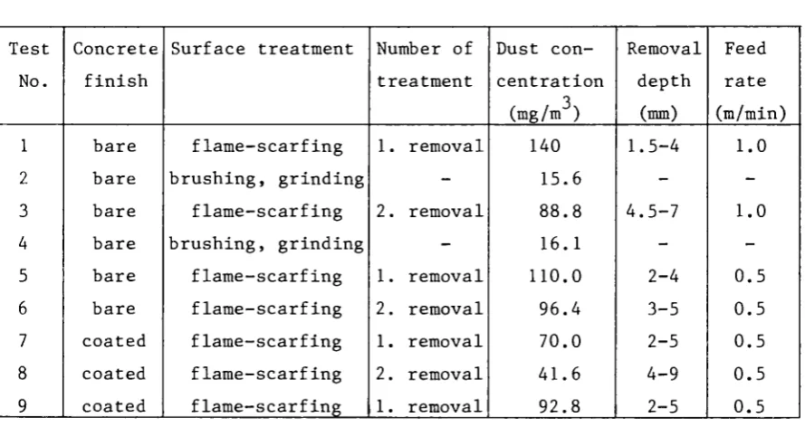
[image:15.595.60.505.445.681.2]The depths of removal and the dust concentration in the exhaust air of the working cabin were measured. The results (Table 1) show that it is possible to reach depths of removal which are sufficient for the decon-tamination of concrete surfaces. During repeated flame-scarfing treat-ments, decreased dust concentrations were measured. In comparison with the previous tests, the dust concentration during burning off was considerably higher, probably due to the finer-grained concrete. For mechanical clean-ing of the burnt-off surfaces, the dust concentration in the cabin exhaust air could be reduced by about a factor of ten by installation of a local suction removal.
Table 1. Dust development and removal depth during flame-scarfing
Test No. 1 2 3 4 5 6 7 8 9 Concrete finish bare bare bare bare bare bare coated coated coated Surface treatment flame-scarfing brushing, grinding flame-scarfing brushing, grinding flame-scarfing flame-scarfing flame-scarfing flame-scarfing flame-scarfing Number of treatment 1. 2. 1. 2. 1. 2. 1. removal -removal -removal removal removal removal removal Dust con-centration (mg/m ) 140 15.6 88.8 16.1 110.0 96.4 70.0 41.6 92.8 Removal depth (mm) 1.5-4 -4.5-7 -2-4 3-5 2-5 4-9 2-5 Feed rate (m/min) 1.0 -1.0 -0.5 0.5 0.5 0.5 0.5
2.1.3.2. Tests on contaminated concrete surfaces
KRB-A. Suitable areas for these tests were selected in the store for low-level radioactive solid operating wastes, considering their history and the expected level of contamination. The areas were coated with PVC varnish and the underlying concrete had finish quality.
In order to determine the contamination having penetrated, boring samples were taken from the surface and examined with a gamma spectrometer. The surface contamination was determined by means of a contamination monitor.
The tests were carried out manually, using a flat-section torch (width: 250 mm) at a feed rate of about 1 m/min. During the tests, a large part of the inner building surface of the solid waste store was decontam-inated. With the help of a mobile aerosol collector, air samples were taken during jet burning in order to determine the aerosol activity. Moreover, the air in the room was analysed for CO and HCl.
The following results were obtained:
—10 —8 2 - initial contamination: 6x10 - 1.5x10 Ci/cm ; - depth of penetration of contamination: 4 - 5 mm; - contamination composition: Cs (90%) and Co;
- removal capacity: 1 - 1.5 mm for each treatment (after four treatments, the decontamination was achieved);
-11 3 - activity in the room atmosphere: 6x10 Ci/m .
The dust-loaded filter was examined using a gamma spectrometer. Only traces of Cs and Co were found in the filter. The bulk of the activity was concentrated in the slag, which was removed after every jet burning, using a floor grinding machine with local suction removal.
Results of the air analyses are given in Table 2. They show that for coatings containing PVC, mechanical removal of the coating is necessary before the jet burning, in order to avoid the release of toxic gases into the atmosphere.
2.2. Erosion of Metal Surfaces by Cavitation at Very High Velocity Contractor: Alsthom-Atlantique Neyrtec, Grenoble, France
Contract N°: DE-B-010-F Work Period: October 1982 - June 1983 (Follow-up to contract N° DE-B-003-F)
2.2.1. Objective and Scope
Table 2. HCl and CO contents (mg/m3) in the room atmosphere during jet burning
HCl CO
Coated surface 56 - 91 77 - 110
Surface with coating rests
2.8 - 5.6 55
Bare surface
-* MAK
7 33 MAK = Maximale Arbeitsplatzkonzentration (maximum allowable work place
concentration) according to "Technische Regeln für gefährliche Arbeitsstoffe TRgA 900"
liquid where pressure is low due to high local velocity. Subsequently, the cavities collapse abruptly, and if this takes place near the surface of a solid, the latter may be eroded. In a first study (contract N° DE-B-003-F), the feasibility of a surface erosion technique employing a cavitation flow of very high velocity was shown, using cavitation elements with one-directional flow.
The present contract is aimed at the development of a new type of cavitation element, based on a circular geometry. This geometry eliminates the side-walls of the cavitation stream and, thereby, the problem of their erosion and the associated energy loss.
2.2.2. Work Programme
A new type of cavitation element, based on a circular geometry, will be designed and tested. The water will be supplied along the central axis, perpendicularly to the target surface and then be diverted to flow radi-ally outward, producing an annular zone of erosion.
2.2.3. Progress and Results
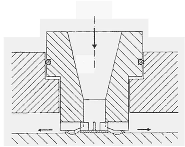
A new circular cavitating nozzle has been designed by optimization of the geometric characteristics of the nozzle used during the previous contract (Figure 1).
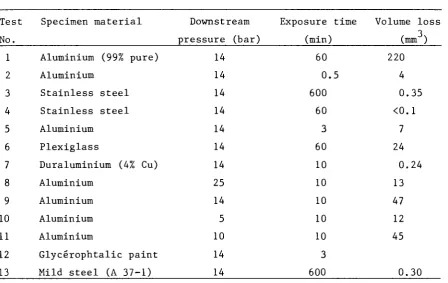
Table 3. Erosion tests using the circular cavitating nozzle
Test No.
Specimen material Downstream
pressure (bar)
Exposure time (min)
Volume loss (mm ) 1 Aluminium (99% pure)
2 Aluminium 3 Stainless steel 4 Stainless steel 5 Aluminium 6 Plexiglass
7 Duraluminium (4% Cu) 8 Aluminium
9 Aluminium 10 Aluminium 11 Aluminium
12 Glycérophtalic paint 13 Mild steel (A 37-1)
14 14 14 14 14 14 14 25 14 5 10 14 14 60 0.5 600 60 3 60 10 10 10 10 10 3 600 220 4 0.35 <0.1 7 24 0.24 13 47 12 45 0.30
The brass of the device was not eroded after twenty hours of service, which produced strong erosion on hard metals like stainless steel.
Another cavitation element, using a vortex flow, is now being designed and will be tested during the next months.
2.3. Composition of Contamination Layers and Efficiency of Decontamination Contractor: Kernkraftwerk Lingen GmbH, Lingen, Germany
Contract N°: DE-B-004-D Work Period: January 1981 - October 1983
2.3.1. Objective and Scope
The purpose of this research is the characterization of, on the one hand, the contamination layers formed in long-term reactor operation and, on the other hand, of the residual contamination after the application of aggressive chemical techniques. These investigations are performed on samples taken from the primary circuit of the Lingen reactor (520 MWth Boiling Water Reactor, shut down in 1977 after nine years of operation).
2.3.2. Work Programme: See Ref. 1, Paragraph 2.4.2.
-2.3.3. Progress and Results
2.3.3.1. Characteristics of contamination layers
Photographic and raster electron microscope examinations of the inner faces of untreated steam and condensate pipe samples were performed. On the steam pipe sample, intercrystalline corrosion attack with an intensity varying over the pipe circumference was found. On the condensate pipe sample, intercrystalline corrosion was less and uniform.
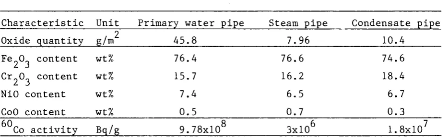
[image:20.595.89.535.308.447.2]Measured characteristics of the oxide layers on pipe samples from the primary water, steam and condensate ducts are summarized in Table 4. Table 4. Characteristics of oxide layers
Characteristic Unit Primary water pipe 2
Oxide quantity g/m 45. 8
Steam pipe Condensate pipe 7.96 10.4 Fe 0 content
Cr 0 content NiO content CoO content
wt% wt% wt% wt%
76.4 15.7
7.4 0.5
76.6 16.2 6.5 0.7
74.6 18.4 6.7 0.3
60 Co activity Bq/g 9.78x10 8 3x10 1.8x10
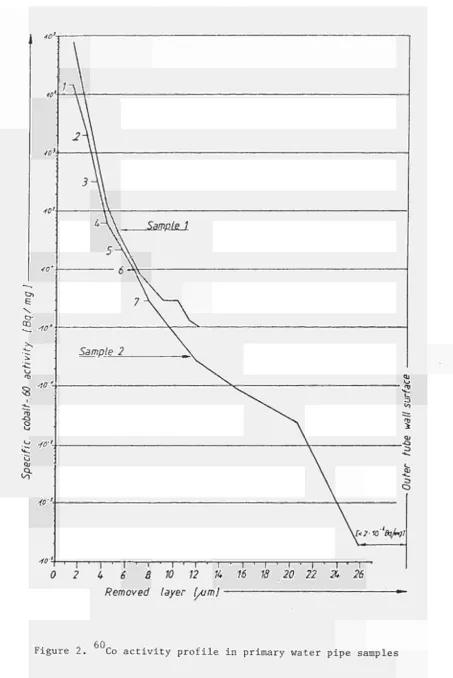
Activity depth profiles have been determined on the pipe samples from the primary water and the condensate ducts. After removal of the oxide layer, base material was electrolytically removed in layers of 1 pm thickness. Subsequently, the activity and metal contents were determined in the electrolytic solutions.
60
Figure 2 shows the Co activity profile in the primary water pipe samples. After removal of 26 um, the Co content equals that of the outer pipe wall. A quite different profile was found in the condensate pipe
fid
2 4 6 8 10
Removed layer Çum]
ι ' ι ·—ι ^π—'—Γ 1 ■—Γ
12 % 16 18 20 22 Ά 26
60
Figure 2. Co activity profile in primary water pipe samples
[image:21.595.63.517.55.734.2]-ι
Τ)
-Qo m·'. 10'
Q j
10'
10·'-Condensate pipe sample 1
Condensate pipe sample 2 ^s
Removed layer [/um] ι.3·η '
10 20 ι — ι — 30
ι r ι τ τ ι — ι - τ Γ — ι — τ ι ' Τ' τ - τ " τ1
[image:22.842.154.742.61.533.2]2.3.3.2. Vigorous decontamination tests
The preliminary tests on material removal by acid treatment of titanium-stabilized AISI 304 stainless steel were finished. The aim of these tests was to achieve uniform removal without pitting, using acid concentrations as low as possible. With an acid content of 1% (HNO /HCl = 1:1), about 25 um were removed in 16 h at 60°C.
2.4. Vigorous Decontamination Tests of Steel Samples in a Special Test Loop
Contractor: Ente Nazionale per l'Energia Elettrica, Rome, Italy
Contract N°: DE-B-005-I Work Period: October 1980 - September 1983
2.4.1. Objective and Scope
The aim of this research is to identify, develop and assess vigorous decontamination techniques. The work involves the design and construction of a special test loop (DECO loop) and experiments using contaminated samples from reactors, in particular from the Garigliano reactor, a 160 MWe BWR shut down in 1978 after 15 years of operation. The decontamination efficiency and other important aspects such as treatment of the spent decontaminant, reliability, operational radiation exposure and costs are investigated. Eventually, a system for in-situ decontamination of a reactor component will be designed.
2.4.2. Work Programme: See Ref.l, Paragraph 2.5.2.
2.4.3. Progress and Results
2.4.3.1. Sample characterization
Most contaminated samples originate from the Garigliano plant. Additionally, two carbon steel samples from the Cirene Assembly Reactor Test loop (CART loop) of the Essor reactor (JRC Ispra) were examined.
Gamma spectrometry with a Ge(Li) detector, on Garigliano samples, showed only the presence of Co; traces of Cs (about 1/1000 of Co) were detected by coincidence analyses. On prepared oxide specimens sub-jected to radiochemistry treatment (for alpha spectrometry), traces of
* Information on this research is also published in Ref. 4.
125c, , 144_ . , , Sb and Ce were also found.
2
The maximum contamination level (1-2 uCi/cm ) was measured on samples from the baffle plate of the Garigliano Secondary Steam Generator A (SSG/A). Preliminary oxide alpha spectrometry showed a total activity of O O T Q 0/1 0.006 uCi/cm with the following composition: Pu: 38%; Am: 38%; 239+240 244
Pu: 23%; Cm: traces. The separation effectiveness was about 30%. On samples from the Garigliano 24" safe-end pipe, an oxide layer of about 10 μτΆ thickness was found by optical microscopy. First observations on secondary electron image by scanning electron microscopy showed an oxide composed by many crystals uniformly spread on a very thin and compact sublayer; semi-quantitative analyses showed that the crystals are mainly nickel-ferrite spinels (NiOFe 0„) with traces of chromium. Traces
of copper and manganese were also found in some samples.
2.4.3.2. Static decontamination tests
Three batch decontamination test series were performed so far.
In the first series, the influence of ultrasound was investigated. In the device used, the activity normally reached a constant level after about 2 min of ultrasonic treatment (Figure 4). Ultrasound enhanced decontamination very effectively when combined with chemical action.
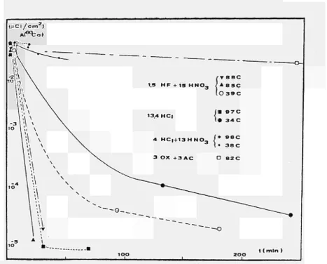
For the second series, activity versus test time is shown in Figure 5. In this series, the influence of reducing the acid concentrations was studied; generally, it causes slowing of the decontamination process. Among the tested solutions, the mixture of hydrofluoric and nitric acid
(1.5 vol.% HF + 5 vol.% HN0_) appears to be the best. Hydrochloric acid, particularly at concentrations of 1-2 vol.%, seems also very effective.
Three tests were performed with organic acids. Two of these tests, using 3 wt% oxalic + 3 wt% citric acid buffered with ammonia at pH=3.5 (one test also with hydrazine as reductant), showed very low decontamina tion factors (1.3-1.5). The third test, with a typical two-step procedure, showed total removal of the oxide and a very high decontamination factor; however, this result is still unexplained.
F i ö ^ i C i / c m Z )
1 AieKboì
Q\ \ \
\ \ -\a \
\ \ λ \
\ \ \ \ -1.25 v v^
\ \
o - \
1
1
1 I
• O t w o t e s t s
- - ^ ~ "~- -.__
2 t ( m l n )
[image:25.595.125.432.60.327.2]I I 1
Figure 4. Influence of ultrasound in a static decontamination test
[image:25.595.56.524.366.742.2]t < m i n )
Figure 5. Static decontamination tests with various chemical agents
When the oxide layer is totally removed, the decontamination factor is very high (>1000). Residual contamination levels are similar to back-ground and below the limits indicated for unrestricted release of material in some countries.
No cracks were found after decontamination. Spent decontaminants from strong mineral acids are treated by particulate removal, followed by metal precipitation with hydrates.
2.4.3.3. Dynamic decontamination tests in the PECO loop
Construction of the dynamic test loop was completed in March and the commissioning tests were performed in June and July 1982.
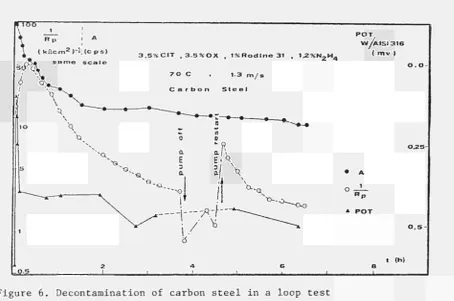
Five decontamination tests were carried out in 1982. They are summarized in Table 5. The evolution of decontamination with time, in the tests No. 1 and No. 2, is shown in Figures 6 and 7, respectively.
Table 5. Conditions and results of dynamic decontamination tests
Test No. Sample material Sample origin Decontaminant (vol.%) Temperature
(°C)
Flow rate (m/s)
Test time (h)
Decontamination factor 1 Carbon steel CART loop organic acids (1) 60-70 1-1.3 6.5 16 2 AISI 304 Garigliano 1.5 HF + 5 HN03
80 1 0.5 >1000 3 AISI 304 Garigliano organic acids (2) 80-90 1 23 (3) 1.7 4 AISI 304 Garigliano 1 HCl 85 1 0.82 3.5 5 AISI 304 Garigliano 0.8 HF + 2.5 HN03
85
1
0.47
>1000
(1) 35 g/1 of oxalic acid + 35 g/1 of citric acid + 12 g/1 of hydrazine + 10 g/1 of inhibitor at pH=3.5 with ammonia.
(2) 1st step: 30 g/1 KMnO + 100 g/1 NaOH; 2nd step: 30 g/1 of oxalic acid + 30 g/1 of citric acid at pH=3.5 with ammonia.
3 . 5 % C I T , 3 . 5 9 6 0 X . 1 % R o d l n e 3 1 , 1.2% Ν « Η Ζ" A
P O T W Á | S I 3 1 6
( m v )
7 O C , 1.3 m / ι
C a r b o n S t e e l
& = L
0 . 2 5
-• A
„ 1
* P O T
0 . 5
[image:27.595.65.520.62.363.2]t (h)
Figure 6. Decontamination of carbon steel in a loop test
» ( c p s )
1.5 H F + 5 H N 03 , 8 0 C , 1 m / s , AtSI 3 0 4
η β
«ι
„ c « ~ «
- β £ β -C
τ α
c ■» c »
t ( m l n )
3 0 - + - + ^ * ·
Figure 7. Decontamination of stainless steel in a loop test
[image:27.595.56.504.397.810.2]2.5. Development of Economical Decontamination Procedures
Contractor: Kernkraftwerk RWE-Bayernwerk GmbH, Gundremmingen, Germany Contract N°: DE-B-006-D Work Period: October 1980 - December 1983
2.5.1. Objective and Scope
The main objective of this research is to identify, develop and assess the most suitable decontamination procedures for decommissioning purposes with particular reference to BWRs. The work involves:
- supplementary contamination measurements, in addition to existing ones, in the KRB-A nuclear power plant (a 237 MWe BWR shut down in 1977 after 11 years of operation);
- decontamination experiments on samples taken from different areas of the primary circuit of the KRB-A reactor;
- evaluation of the experimental results in respect of both the KRB-A reactor and a 1200 MWe BWR.
2.5.2. Work Programme: See Ref. 1, Paragraph 2.6.2.
2.5.3. Progress and Results
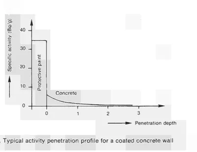
2.5.3.1. Penetration of contamination into concrete structures
The penetration of contamination into the concrete walls and floors was measured on boring samples of 55 mm diameter and 30 mm length, taken at 17 selected locations of the controlled area. Cesium showed a much higher penetration capability than cobalt.
2.5.3.2. Decontamination tests
Previous tests had shown, that the usual two-step chemical decontam-ination procedures and attack by aggressive acids would require at least three consecutive treatments with fresh solutions, to reduce contamination on primary loop pipes below the limit for unrestricted release. Thereupon, electrochemical decontamination, which seems more promising as an economi-cally suitable procedure, has been investigated.
70% phosphoric acid was chosen as electrolyte and the current
density was varied between 0.31 and 3.12 A/cm2. The decontamination
velocity is roughly proportional to the density and high densities are necessary for short treatment times (see Figure 9 ) .
This reference method did not in all cases achieve complete oxide removal. Pre-treatment with commercial detergents proved to be very effective on ferritic steel samples from the condensate duct, removing 80-90% of cobalt-60 and 30-40% of cesium. A subsequent electrolytic treatment with 23.4 A/dm2 removed almost all remaining contamination.
Stirring the solution vigorously did not significantly improve the decontamination. Reducing the phosphoric acid concentration from 70% to 40% resulted in preferred attack of surfaces where oxide layers were thin, and in higher residual contamination. A mixture of concentrated sulphuric acid and 70% phosphoric acid brought no improvement, even when vigorously stirred.
Tests with and without detergent pre-treatment were repeated on samples from the primary steam duct. Electropolishing is very efficient on this material, which has a higher chromium content. On these samples, the total decontamination factor was slightly increased by the pre-treatment.
Analyses of the electrolyte showed a steady increase of the metal content (Fe, Cu, Ni, Cr, Mn, Co). No reduction of efficiency was observed with iron contents up to 23 g/1.
2.6. Development of Gel-based Decontaminants
Contractor: Commissariat à l'Energie Atomique, CEN Saclay, France
Contract N°: DE-B-007-F Work Period: February 1981 - September 1982
2.6.1. Objective and Scope
Existing decontamination techniques employ usually abundant quanti-ties of liquid decontaminant and, consequently, produce large volumes of
O) CT m
">
o
CC
o
CD Q .
ω
40
30
-20 _
10
-co Q. CD
>
Õ Q) O
i _ 0_
Concrete
T 3
-*»~ Penetration depth
Figure 8. Typical activity penetration profile for a coated concrete wall
CT m
υ co o
'TD co
cr
104 .
1 03.
1 02.
2 J O1 I
.
l = o·
3 1c 4
—I 1
1 = 0.42 -£5-cm2
—1 1
1=0.65 ~
cm2
—1 1 Β »
0 30 90 0 30 90 0 30 90 time (min)
[image:30.595.143.544.63.372.2] [image:30.595.185.522.425.686.2]radioactive effluent. Less decontaminant is required, if the decontaminant is applied by means of a gelatineous carrier substance.
The objective of this research is to develop a decontamination tech-nique using highly effective gel-based decontaminants, which is capable of ensuring:
- a reduction of the time during which personnel is exposed to radiation;
- a reduction of the contamination of a component, thereby enabling it to be decontaminated more thoroughly after its transfer to the decontamination bays;
- the decontamination of vertical walls;
- a reduction of the quantity of radioactive effluents resulting from decontamination.
2.6.2. Work Programme: See Ref. 1, Paragraph 2.7.2.
2.6.3. Progress and Results
2.6.3.1. Decontamination of artificially contaminated samples
Samples of stainless steel, mild steel, an aluminium magnesium alloy, copper and plexiglass were contaminated by applying a solution
137 90 90 239 containing either fission products ( Cs, Sr, Y) or Pu. After drying for 24 h and activity measurement, the samples were rinsed in water and measured for fixed activity. The samples were then decontaminated by applying gels containing decontaminants and, for comparison, by immersion in an aqueous solution of decontaminants. Finally, the residual activity was measured.
The efficiency of decontamination is valued by the decontamination factor (DF) defined as the ratio of fixed activity to residual activity.
The following mixtures of gels and decontaminants were studied:
- glycerophtalic gel as carrier of sulphamic, oxalic, citric, tartaric and sulphuric aciti;
- glycerophosphoric gel alone and as carrier of phosphoric acid or of a commercial phosphoric detergent;
- silica gel as carrier of sulphuric or nitric acid;
- diopside gel as carrier of sodium hydroxide and potassium perman-ganate.
On stainless steel (AISI 304L), compounds of glycerophosphoric gel gave decontamination factors between 20 and 200, values obtained likewise with silica gel as carrier of nitric or sulphuric acid. Decontamination for plutonium on stainless steel is effective with glycerophtalic gel as carrier of sulphuric acid (DF=165) or with diopside gel as carrier of sodium hydroxide and potassium permanganate (DF=740).
On mild steel, decontamination factors higher than 100 were obtained with glycerophtalic gel as carrier of sulphamic acid and a tensio-active commercial product (nonylphenol-polyglycol-ether), or with silica gel as carrier of sulphuric acid.
Aluminium is well decontaminated by diopside gel as carrier of sodium hydroxide and potassium permanganate for plutonium and by silica gel as carrier of sulphuric acid for fission products (DF=810).
On copper, sulphuric acid carried by glycerophtalic gel or silica gel gives good decontamination (DF>80).
Plexiglass is well decontaminated by glycerophosphoric gel as carrier of phosphoric detergent or by diopside gel as carrier of sodium hydroxide and potassium permanganate.
2.6.3.2. Treatment of secondary waste
The efficiency of decontamination by evaporation of aqueous radioac-tive wastes is not changed if 10% of contaminated gels are added to these wastes.
2.7. Metal Decontamination by Chemical and Electrochemical Methods and by Water Lance
Contractor: Commissariat à l'Energie Atomique, CEN Cadarache, France Contract N": DE-B-008-F Work Period: January 1981 - December 1983
2.7.1. Objective and Scope
The aim of this research is to develop highly effective methods for the decontamination of steel for decommissioning purposes.
Decontamination by high-pressure (700 bars) water lance will also be studied, including the "hardening" of the liquid jet by the addition of solids (salts of low or slow solubility or inert abrasives) and the combination of chemical treatment and water lance.
The methods thus optimized will be evaluated with a view to their industrial application, taking into account, in particular, their effecti-veness, limitations, costs and radiological consequences.
2.7.2. Work Programme: See Ref. 1, Paragraph 2.8.2.
2.7.3. Progress and Results
Decontamination tests were performed on samples from an electromag-netic filter used for 20 months in the primary circuit of a PWR (Advanced Prototype Nuclear Steam Supply System at Cadarache). For these stainless steel parts, two-step chemical treatments give good results, if strong acids are used in the second step. The main part of the research was aimed at finding the best pre-treatment allowing easy decontamination and secondary waste treatment.
With pre-treatment by soda permanganate (1 h at 85°C), followed by treatment at room temperature, 0.5 mol/1 HF + 2 mol/1 HNO gave the best results. The efficiency was enhanced by treatment at 85°C. Sulphuric acid in place of nitric acid also produced good decontamination.
Of the other solutions tested, only ozone pre-treatment and electro-lytic oxidation of the surfaces with a contaminated oxide layer appear to be promising.
Ozone sparging tests were conducted under alkaline and acid condi-tions and in demineralized water. Only the results obtained with deminera-lized water were encouraging. The mechanical action of sparging was found important.
The effectiveness of the pre-treatment can be evaluated by the amount of chromium removed from the oxide layer. This amount was approxim-ately the same with the following pre-treatments:
a) soda permanganate solution (1 h);
b) anodizing in soda medium (100 mA/cm2, 0.5 h); c) sparging with 2.5% ozone in oxygen (7 h).
Treatment with fluoric-nitric baths (0.05 mol/1 HF + 2 mol/1 HNO ; 8 h at 25°C) gave decontamination factors of 2000, 170 and 400 with the
above-mentioned pre-treatments a, b and c, respectively. In all experi-ments, the results with ozone pre-treatment were found to be 2 to 5 times
lower and the results with electrolytic oxidation about 10 times lower than those with soda permanganate.
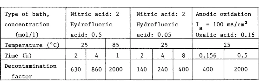
[image:34.595.89.536.266.406.2]The additional application of ultrasound during the decontamination treatment regularly produced 5 to 10 times higher decontamination factors. For samples pre-treated by ozone sparging in demineralized water, various methods of chemical and anodic oxidation were tested (Table 6).
Table 6. Decontamination tests on samples pre-treated by ozone sparging
Type of bath, concentration (mol/1) Temperature (°C) Time (h) Decontamination factor
Nitric acid: 2 Hydrofluoric acid: 0.5 25 2 630 4 860 85 1 2000
Nitric acid: 2 Hydrofluoric acid: 0.05 25 2 140 4 240 8 400 Anodic oxidation I = 100 mA/cm2
a
Oxalic acid: 0.16 25
0.156
400
0.5
2000
Regarding the treatment of spent decontaminants, it was shown that oxalic acid can be oxidized by electrolysis on a glassy carbon anode and thereby removed up to 99% from spent baths before coprecipitation of residual oxalates and of radiochemical activity by lime.
2.8. Economic Assessment of Decontamination for Unrestricted Release Contractor: Nuklear-Ingenieur-Service GmbH, Hanau, Germany
Contract N°: DE-B-009-D Work Period: February 1981 - March 1982
2.8.1. Objective and Scope
2.8.2. Work Programme: See Ref. 1, Paragraph 2.9.2.
2.8.3. Progress and Results
Authorizations for unrestricted release of material from the con-trolled area of nuclear facilities are mostly granted on a case-by-case basis. Agreed procedures have been set up for a number of facilities in co-operation with the licensing authorities. Considering the Euratom Basic Safety Standards and the Recommendations of the International Commission on Radiological Protection (ICRP-26), the licences have been discussed in order to evolve ideas and tendencies about possible future criteria for unrestricted release.
Available relevant information on contamination and on decontamina-tion techniques was reviewed.
As the decontamination techniques for unrestricted release purposes are in an early stage of development, at least for stainless steel, no reliable cost data for this kind of decontamination are readily available. The costs for the management of steel waste without extensive decontamination were estimated, considering three disposal modes, i.e., sea dumping, disposal in a salt mine and shallow land burial.
This estimate was based on average labour costs of 90 DM/man-hour and on the following waste package characteristics:
- drum volume: 200 1 - drum mass: 40 kg - steel mass: 312 kg
- concrete mass: 268 kg (filling mass)
- filling factor: 0.2 (steel volume to available volume)
The following costs (DM per Mg net mass) were estimated for the individual operations:
Cutting
- 10 man-hours: - material:
900 50 950
Transportation - 100 km by truck: - 400 km by railway: - surveillance:
92 278 30 400
-Conditioning - 4 man-hours: - material: - 3 drums:
360 310 945
Disposal (three options)
- embarking, sea dumping: 945
- land burial: 1400 - mine disposal (Asse): 3200
1615
The total costs (DM per Mg net mass) of the above-mentioned opera-tions are as follows:
- total cost with sea dumping: 3910 - total cost with land burial: 4365 - total cost with mine disposal (Asse): 6165
3. PROJECT N° 3: DISMANTLING TECHNIQUES
For the removal of a nuclear power plant, thick-walled steel compo nents (e.g. reactor pressure vessel) and reinforced concrete structures
(e.g. reactor shielding) must be dismantled. Here, the radioactivity demands particular requirements such as remote operation, minimum dust formation and air cleaning.
The following techniques are being examined and developed:
- thermal techniques such as plasma-arc and oxygen cutting and cutting by laser beam;
- mechanical cutting techniques such as sawing;
- explosive techniques for the dismantling of concrete structures; - cutting of metals by intergranular fissuration.
3.1. Thermal and Mechanical Dismantling Techniques Contractor: Transnuklear GmbH, Hanau, Germany
Contract N°: DE-C-001-D Work Period: March 1980 - June 1982 3.1.1. Objective and Scope
The purpose of this research was to try out various dismantling techniques on non-radioactive test specimens representative of components and structures of light water reactors and to evaluate these techniques as to performance, radiation exposure of personnel and environmental impact. 3.1.2. Work Programme: See Ref. 1, Paragraph 3.1.2.
3.1.3. Progress and Results
The research w a s completed in the first half of 1982 b y the w o r k s described in the following.
3.1.3.1. Complementary tests with the powder cutting technique
Tests with the powder cutting technique were carried out in order to determine the dust content and particle size distribution in the off-gas. A heavy concrete plate (thickness: 60 cm; density: 4 g / c m3) and a carbon
steel I-girder were used as test specimens.
The measured dust contents were 3.0 g/m3 and 1.2 g/m3 for cutting
concrete and s t e e l , respectively. The results obtained with the oxygen
lance had been 0.9-1.5 g/m3 and 2.3 g/m3 for concrete and steel, respec tively. However, in comparing these data, the larger cutting speed of powder cutting has to be taken into account.
The largest fraction of particles occurred at a size of 0.3 μπι. Compared with the oxygen lance, powder cutting produced a smaller propor tion of fine particles, especially when steel was cut.
3.1.3.2. Investigation of sawing techniques
[image:38.595.85.534.320.427.2]Using a bow saw, cutting tests on a carbon steel I-girder were carried out. The results are compared in Table 7 with those obtained with thermal techniques.
Table 7. Cutting of an I-girder using various techniques
Cutting technique Bow saw
Oxyacetylene torch Oxygen lance 3/8" Powder cutting
Cutting time (min) 15
23 2.1 1.2
* Waste (kg)
0.56 0.50 4.1 1.3 Chips (sawing) or slag (thermal techniques)
Moreover, the following sawing techniques were tested:
- a high-speed, dry-operation circular saw (diameter: 520 mm) for cutting pipes;
- low-speed circular saws (diameters: 560 mm, 500 mm) for cutting round steel;
- a high-speed, corundum-coated disk (diameter: 905 mm) for cutting concrete.
3.1.4. Conclusions
The following conclusions were drawn from the work performed under this contract.
Of the three oxygen lances (1/4", 3/8" and 1/2") tested, the 1/4" lance is best for cutting heavy concrete; in particular, the slag deposit is very small. For steel, however, the 3/8" lance is superior.
respect to cutting rate, suitability for remote control and, to some extent, slag deposition. The cutting depth on concrete achievable with the available powder cutting equipment was limited to about one metre.
The oxyacetylene torch, whose application is restricted to ferritic steels, is characterized by little dust and slag formation, low gas consumption and negligible tendency to malfunction.
The plasma torch produced good results in cutting austenitic and ferritic steel plates; it is, however, prone to malfunction, especially on workpieces with irregular geometry.
Thermal cutting techniques produce a large amount of fine aerosols. With an exhaust flow of 2200 m3/h, the dust content in the off-gas ranged from 1 to 3 g/m3 as a function of the cutting technique and the material. The largest fraction of particles occurs at a size of 0.3 μτη. Thermal cutting of radioactive material, therefore, requires a major off-gas filtering effort. In particular, filters must be fit for cleaning in order to attain adequate service time. Two such filter systems were tested, i.e. a cartridge-type filter, which showed only moderate efficiency (81-85%), and a HEPA filter, which achieved an efficiency of 99.96%.
Sawing techniques have advantages in producing almost no airborne contamination and little secondary waste. Also, they are suitable for remote operation. However, due to the limitation of cutting depth, normal sawing equipment cannot be used for the initial dismantling of large components.
The final report on this research is being published (Ref. 6).
3.2. Plasma Techniques for Cutting Mineral and Metal Materials Contractor: Ansaldo Meccanica Nucleare, Genoa, Italy
Contract N°: DE-C-002-I Work Period: October 1980 - December 1983
3.2.1. Objective and Scope
This research relates to plasma-arc cutting and its basic aim is to provide more information on the process, to bring the various cutting techniques more closely into line, from a technical and economic stand point, with the various possible applications in the dismantling of nuclear power plants, and to improve the safety and reliability of these techniques.
The plasma-arc cutting technique will be studied independently of
the type of power station in which its use is envisaged; however, where specific examples have to be considered, the contractor will, as a licen-see for Boiling Water Reactor stations, refer to this type of plant.
3.2.2. Work Programme: See Ref.l, Paragraph 3.2.2.
3.2.3. Progress and Results
During 1982, two techniques have continued to be developed, i.e. the plasma torch for cutting steel components and the oxygen lance for cutting concrete structures.
3.2.3.1. Plasma cutting
AMN, in co-operation with Messer Griesheim, continued the optimiza-tion of the cutting parameters.
Two types of torch were used, i.e. the plane-shaped electrode torch and the pointed electrode torch. The cutting tests were performed in air and under water with steel AISI 304 samples of 40 mm thickness. These tests showed that:
- the utilization of both torch types presents no difficulties; - cutting rates are reproducible;
- the nozzle life is satisfactory, provided the distance between the nozzle and the work-piece is correct.
A second series of tests was performed to investigate the possibi-lity of cutting tubes close to a wall. This problem relates to the sever-ing of a recirculation inlet tube in a BWR. The analyses of these tests are in progress.
At the beginning of 1983, another series of tests will be started, in order to determine the maximum thickness that can be cut and to charac-terize the dust and aerosols produced in cutting different steel plates.
3.2.3.2. Oxygen lance
in slowing down the perforation process and caused sometimes large devia-tions from the straight path. The best slope angle in the cut is about 25°, a horizontal cut is not recommended. Since the large amounts of lapilli which are ejected from the cut could damage components that are behind the structure being dismantled, it is recommended to remove or to shield the components that are to be preserved.
3.2.3.3. Analysis of radiological protection and safety aspects
The experiments relating to radiological protection and safety aspects, which are to be carried out at the ENEA Casaccia Centre, have been delayed due to problems of commissioning the equipment and instrumen-tation. The tests are now planned to be carried out in 1983.
3.3. Diamond-tipped Saws for Cutting Concrete Structures
Contractor: Central Electricity Generating Board, Barnwood, United Kingdom
Contract Nc: DE-C-003-UK Work Period: April 1980 - December 1983
3.3.1. Objective and Scope
The objective of this research is to develop a suitable diamond saw capable of cutting away remotely the inner 1 m activated layer of a reinforced concrete biological shield or pre-stressed concrete pressure vessel. Since the dose rates within these structures will be too high to permit manual work for practical periods, the saw must be capable of being remotely controlled and operating reliably for long periods. In addition, the cooling system must be designed to be efficient but produce the minimum practical amount of slurry.
This research concerns all types of nuclear power plants.
3.3.2. Work Programme: See Ref. 1, Paragraph 3.3.2.
3.3.3. Progress and Results
In 1982, the development of large diamond-tipped circular saws was continued satisfactorily. Two blades were manufactured, i.e.:
- a blade of 0.6 m diameter, to cut the relatively thin surface layer of concrete covering the reinforcement bars and the bars themselves;
- a blade of 2.5 m diameter, to cut up to 1 m deep into high quality
concrete.
Construction of the power pack and the saw unit and delivery to the test site at Portishead Power Station, implementation of work and preli-minary testing were successfully completed.
3.3.3.1. Implementation of work
For the implementation of the saw unit, the following work had to be carried out.
The power pack and saw frame hydraulic systems were connected and operated at full pressure of about 200 bar to demonstrate their service-ability.
The tracking of the saw frame was checked and adjusted so that it was as exact as possible. A misalignment of only 7 minutes of arc produces a deviation of +2.5 mm at the leading edge and -2.5 mm at the trailing edge of the 2.5 m diameter blade when cutting 1 m deep. This results in hysteresis in the blade, more power being needed to cut a given length of kerf, and a kerf wider at the top than the bottom.
The response characteristics of the controller were adjusted so that the power required to feed or plunge the blade into the concrete, or to traverse the blade through the concrete did not exceed the power available and thus cause a stall. In particular, the saw has to decelerate when moving out of the relatively free cutting concrete and into the more resistant reinforcing steel. This has now been achieved.
A method of moving the saw frame from one test site to another without affecting the positional accuracy of the sawing was developed. This is now a matter of routine.
Factors affecting the tracking, such as external forces applied by the hydraulic hoses, were reduced to a minimum.
3.3.3.2. Preliminary tests
3.4. Plasma-oxygen Cutting of Steel Pressure Vessels Contractor: Salzgitter AG, Salzgitter, Germany
Contract N°: DE-C-004-D Work Period: April 1980 - December 1983
3.4.1. Objective and Scope
The purpose of this research is the development of a technique based on a combination of plasma and oxygen torches, capable of cutting up from the clad side thick sections of low-alloy steel clad with stainless steel, occuring in the pressure vessel of light water reactors.
The work comprises cutting tests on thick (up to 600 mm) inactive specimens, optimization of cutting parameters and off-gas filtering system, and a concept study of dismantling reactor pressure vessels.
3.4.2. Work Programme: See Ref. 1, Paragraph 3.4.2.
3.4.3. Progress and Results
The development of a combined cutting torch which consists of a plasma torch and an oxyacetylene torch has been continued.
3.4.3.1. Cutting tests on thick plates of ferritic steel clad with stainless steel
The systematic test series with the combined plasma-oxyacetylene torch have been extended to include the thickness range of clad plates of 400 to 600 mm in various cutting positions, i.e.:
- flat position (vertical torch moving horizontally);
- horizontal position (horizontal torch moving horizontally); - vertical position (horizontal torch moving downwards).
The base material used was ferritic steel grade St 37-2 (thickness: 150, 200, 250, 300, 400 and 600 mm) and the cladding consisted of auste-nitic steel grade XlOCrNiTi 18 8 (thickness: 10 mm). These tests confirmed that the cutting of clad ferritic steel with this technique is possible up to a thickness of 600 mm. However, the 600 mm specimens required maximum cutting speed of the oxyacetylene torch in order to avoid break-down of the plasma arc; as a consequence, a lower quality of cut must be accepted. The vertical cutting position proved to be the most favourable one, for the following reasons: the slag falls onto the hot end of the kerf; the heating of the oxyacetylene torch can be reduced by setting at
priate distance to the workpiece; the hot process gas rises within the kerf and contributes to a better quality of cut. In the horizontal cutting position, the slag falls onto the flank of the kerf, which leads to an unclean cut. In the flat cutting position, the oxyacetylene torch is strongly heated up by rising hot gas.
[image:44.595.84.531.254.641.2]Table 8 shows the optimized cutting parameters for the flat and vertical cutting positions.
Table 8. Optimized cutting parameters
Base material thickness Nozzle 0 of plasma torch Angle of plasma torch Current
Voltage
Nozzle of oxyacetylene torch
Distance oxyacetylene torch - workpiece Angle of oxyacetylene torch
Pressure of fuel gas Pressure of fuel oxygen Pressure of cutting oxygen
Cutting speed Cutting depth Width of kerf
Distance between torches
Unit mm mm degree A . V -mm degree bar bar bar mm/min mm mm mm Flat position
150 200 250 300 400 600
Vertical position 400 600 4.5
45 30
200 150
typ e 200-300 mm
8 12
5 0.22 3.5 14 140 160 18 120 210 20 90 260 130
type 300-600 mm
37 35
0 1.1 7 17 60 310 12-20 30
410 610 410 610 20
40 39
3.4.3.2. Characterization of aerosols and testing of filter systems
For these investigations, aerosols were produced by plasma cutting of ferritic and of austenitic steel specimens and by oxyacetylene cutting of ferritic steel specimens. The specimen thickness was 20 and 40 mm.
and 0.12 pm for the austenitic and the ferritic steel specimens, respec-tively. On cutting of ferritic steel both with the oxyacetylene torch and with the plasma torch, the largest fraction of particles occurred at the same size. When cutting with the oxyacetylene torch, the range of particle sizes was narrower and the proportion of fine particles was lower.
Three filter systems connected in series were tested. The following average efficiencies were obtained for each of the systems:
- bulk material type filter: 87.5%
- box type filter: 91% - barrel type HEPA filter: 84%
Therewith, the overall efficiency of the three systems is 99.8%. However, the bulk material type filter, used as pre-filter, did not attain adequate service life and should therefore be replaced by a different filter.
3.5. Dismantling of Concrete Structures and Metal Components Using Laser Contractor: FIAT TTG SpA, Torino
Contract N°: DE-C-005-I Work Period: April 1981 - December 1983
3.5.1. Objective and Scope
The aim of this research is to study laser techniques for the following applications in particular:
- drilling holes in prestressed and ordinary reinforced concrete for placing explosive charges with a view to demolition;
- cutting reinforced concrete structures;
- cutting thin and medium-thick metal components.
The laser cutting technique will be studied independently of the type of nuclear power station in which its use is envisaged; however, where specific examples have to be considered, Pressurized Water Reactor
stations and Gas-cooled Reactor stations will be referred to.
3.5.2. Work Programme: See Ref. 1, Paragraph 3.5.2.
3.5.3. Progress and Results
The development of the cutting technique using the 15 kW carbon dioxide laser has been continued in 1982. Due to laser malfunction, the tests scheduled for the second half of 1982 had to be postponed to 1983.
-3.5.3.1. Development of equipment
Nozzles of various diameters for one or several assistant gas jets were manufactured. In parallel, a nozzle design was developed which permits to supply the gas co-axially to the laser beam.
3.5.3.2. Cutting and drilling of concrete
Preliminary experiments on concrete produced encouraging results. Oxygen at a pressure of 7 bar as assistant gas and a needle-valve nozzle of 1.5 mm diameter proved to be appropriate. Cuts of 90 mm depth were performed with 10 kW power and 0.02 m/min velocity. The kerfs were regular and only 2 mm wide. Furthermore, holes of 8 mm diameter and 65 mm depth were drilled, using an impulse of 5 s at a power of 10 kW.
3.5.3.3. Cutting of steel
Cutting tests on steel were done with 10 kW power and oxygen as assistant gas. Two types of specimens were used, i.e.:
- 40 mm thick plates of low-carbon mild steel grade Fe 42 C; - 45 mm thick plates of stainless steel grade AISI 304.
The position of the beam focus was optimized with respect to cutting velocity. For the stainless steel specimens, moving the focus from the specimen surface to the optimum position, which was found to be 15 mm beneath the surface, allowed to rise the cutting rate from 0.21 m/min to 0.27 m/min. For the mild steel specimens, a cutting rate of 0.41 m/min was achieved. In order to achieve these maximum cutting rates, the oxygen flow must exceed a critical value, which was found to be 6 m3/h and 7 m3/h for the stainless steel specimens and the mild steel specimens, respectively.
3.5.3.4. Analysis of by-products
Off-gas samples taken during the cutting tests described in the two preceding paragraphs were analysed. The following dust concentrations, corresponding to an exhaust flow rate of 1350 m3/h, were determined for the various specimen materials (rounded average values):
- stainless steel: 40 mg/m3; - mild steel: 20 mg/m3; - concrete: 370 mg/m3.
smaller than 0.3 um could not be determined with the apparatus used for these first measurements.
Preliminary analyses for trace element concentrations in the dust were carried out.
3.6. Explosive Demolition Techniques for Concrete Structures
Contractor: Taylor Woodrow Construction Ltd, Southall, United Kingdom Contract N°: DE-C-006-UK Work Period: January 1981 - December 1983
3.6.1. Objective and Scope
The objective of this research is to optimize and assess explosive techniques for the demolition of the radioactive concrete structures of nuclear power plants in respect to safety, radiation protection and costs.
The research is directed mainly at the biological shields of early Magnox reactors and the prestressed concrete pressure vessels (PCPV) of later Magnox and Advanced Gas-cooled Reactors. Relevant structures of other commercial nuclear power plants in the European Community, in particular the PCPVs of French Gas Graphite Reactors and the biological shields of light water reactors, will also be considered.
3.6.2. Work Programme: See Ref. 2, Paragraph 3.6.2.
3.6.3. Progress and Results
3.6.3.1 Cratering Tests
Preliminary tests: These tests were carried out on an existing concrete block to help decide target sizes to be used in subsequent work. 4 gram charges at 200 mm depth of burial were fired near the four corners of the concrete block. The distances from the edges were varied between tests. From these preliminary studies a target size of 0.5 m dia χ 0.5 m thick was considered to be suitable for the small-scale tests.
Depth of burial and charge weight effects - untamped (7 tests): Depth of burial effects on cratering were checked using untamped 4 gram charges in models with depths of burial of 50, 75, 100 and 125 mm. The charge weight effects on cratering were investigated using untamped 6, 8 and 10 gram charges at 125 mm depth of burial. Only one true crater was formed, i.e. with 50 mm depth of burial. In all other tests, a camouflet
or partial camouflet was formed. These tests indicated that considerable energy was lost in "blow back" because the charge holes were untamped.
Depth of burial effects - tamped (4 tests): Repeat tests with improved tamping were carried out, for the four cases in which depth of burial effects were investigated earlier. Damage in all cases was more severe than with the untamped tests and with crater diameter increasing with depth of burial up to a critical depth of 100 mm. However, other damage to the models indicated that the diameter of the models may have been too small so that boundary proximity produced effects giving unrepre-sentative crater diameters.
Concrete strength effects - tamped (2 tests): A weak and a strong model were tested to complement a mean strength test carried out earlier. The results indicated that variations in concrete strength had very little effect on cratering. Size of the models and boundary proximity effects may, however, have masked any differences.
Reinforcement effects - tamped (3 tests) : Three models were tested in which the front faces were reinforced. The indications were that the presence of reinforcement distributed the explosive forces over a wider area resulting in models with larger scabbed areas. It would appear that a slight reduction in crater diameters was also obtained.
Scaling effects - tamped (3 tests) : The validity of model techniques and scaling effects have been assessed by testing three structures in which linear dimensions were increased by a factor of four over previously tested small-scale models. The results indicated there was very close agreement in damage characteristics between the models of both sizes with crater parameters scaling up in proportion.
Shape effects - tamped (3 tests): Earlier tests had indicated that the size of the models being used might be too small with edge effects influencing the test results. To investigate this, three large diameter models, but with characteristics similar to previous models, were tested. These initial tests indicated that the results from the smaller models may have been exaggerated by boundary effects. Further tests are to be carried out to investigate this in detail.
3.6.3.2. Boring tests with shaped charges