Ames Laboratory ISC Technical Reports Ames Laboratory
9-3-1954
A countercurrent liquid-liquid extractor
Harley A. Wilhelm
Iowa State College
Raymond A. Foos
Iowa State CollegeFollow this and additional works at:http://lib.dr.iastate.edu/ameslab_iscreports Part of theChemistry Commons, and theEngineering Commons
This Report is brought to you for free and open access by the Ames Laboratory at Iowa State University Digital Repository. It has been accepted for inclusion in Ames Laboratory ISC Technical Reports by an authorized administrator of Iowa State University Digital Repository. For more information, please [email protected].
Recommended Citation
Wilhelm, Harley A. and Foos, Raymond A., "A countercurrent liquid-liquid extractor" (1954).Ames Laboratory ISC Technical Reports. 76.
A countercurrent liquid-liquid extractor
Abstract
A novel countercurrent liquid-liquid extractor is presented and illustrated with applications. The apparatus consists essentially of an assembly of mixer-settlers, feeders, reservoirs, and flow lines that are made of glass or other chemical resistant materials. In operation this multistage assembly rotates intermittently in one direction on a horizontal axis causing the immiscible phases to progress to opposite ends of the unit. Details for the construction of the extractor and its principles of operation are given. Extractors of this design are applicable to experimental work and to the preparation of pure compounds in quantity.
Keywords Ames Laboratory Disciplines
Chemistry | Engineering
low~
~~
~CLASSIFIED
rsc..-J~-5'1
UNClASSIFIED
r
.
\
ISC-458
UNITED STATES ATOMIC ENERGY COMMISSION
A COUNTERCURRENT LIQUID-LIQUID EXTRACTOR
By
Harley A. Wilhelm Raymond A. Foos
September 3, 1954
Ames Laboratory Ames, Iowa
Date Declassified: September
8, 1955.
This report was prepared as a scientific account of Govern-ment-sponsored work and is made available without review or examination by the Government. Neither the United States, nor the Commission, nor any person acting on behalf of the Commis-sion makes any warranty or representation, express or imp I ied, with respect to the accuracy, completeness, or usefulness of the information contained in this report, or that the use of any infor-mation, apparatus, method, or process disclosed in this report may not infringe privately owned rights. The Commission assumes no I iabi lity with respect to the use of, or for damages resulting with respect to the use of any information, apparatus, method, or proc-ess disclosed in this report.
This report has been reproduced directly from the best
available copy.
Issuance of this document does not constitute authority for declassification of classified material of the same or similar content and title by the same authors.
Printed in USA, Price 30 cents. Available from the
ISC-458
A COUNTERCURRENT LIQUID-LIQUID EXTRACTOR
by
Harley A. Wilhelm and Raymond A. Foos
September
3,
1954Ames Laboratory at
Iowa State College F. H. Spedding, Director
Contract W-7405 eng-82
4
ABSTRACT. • ••
INTRODUCTION. .
ISC-458
TABLE OF CONTENTS
PRINCIPLES OF OPERATION OF THE EXTRACTOR. •
0 0 • 5
• o5
SOME DETAILS OF THE EXTRACTOR DESIGN AND OPErtATION. o • • 14
A PROCEDURE FOR STARTING THE EXTRACTOR.
SEPARATION OF SOME INORGANIC SALTS. o o
.
.
0 0 0 0 0 0 .20 .21 0 01. Separation of Zirconium from Hafnium • o • • • • 21
a. Separation of Zirconium from Hafnium in
An Intermediate Composition Mixture • • • • 22 b. Separation of Small Amounts of Zirconium
from Hafnium • • • • • • o o o • • o • • • o24
2. Separation of Tantalum from Niobium. 0 0 0 0
MODIFICATIONS OF THE EXTRACTOR. • 0 0
0 o27
.30
o36 DISCUSSION • • •
ACKNOWLEDGMENTS o
REFERENCES • • •
0 0 0 0
0 0 0 0 0 0 0 0 0 0 0 38
ISC-458
A COUNTERCURRENT LIQUID-LIQUID EXTRACTOR
by
Harley A. Wilhelm and Raymond A. Foos
ABSTRACT
A novel countercurrent liquid-liquid extractor is presented and illustrated with applications. The apparatus consists essentially of an assembly of mixer-settlers, feeders, reservoirs, and flow lines that are made of glass or other chemical resistant materials. In operation this multistage assembly rotates intermit-tently in one direction on a horizontal axis causing the immiscible phases to progress to opposite ends of the Ynit. Details for the construction of the extrac-tor and its principles of operation are given. Extrac-tors of this design are applicable to experimental work and to the preparation of pure compounds in quantity.
The applicability of the extractor is illustrated by extractions involving zirconium and hafnium, and niobium and tantalum. A fraction containing high purity hafnium and one containing high purity zirconium were obtained from a liquid solution containing roughly equal amounts of both. Another extraction produced zirconium of high purity from a mixture containing largely hafnium. Niobium and tantalum were also successfully separated.
INTRODUCTION
5
Ddr~ng the p~bt few decades liquid-liquid extraction has become one of the principal methods of performing separations and purifications on both laboratory and commercial scales. Partial or complete separation -Pr purification of rare earth mixtures
(1-4), atabrine
(5),
penicillin(6),
vitamins(7),
normal fatty acids (8) higher fatty acids(9),
bile acids (10h monoamineacids
(11~,
antimony (12) and hafnium-zirconium mixtures (13) are only a few applications of this unit operation being investigated or employed today. Von Berg and Wiegandt (14) state that this principle is most widely employed in the petroleum industry for fractionation of oil mixtures although its use is gradually6 ISC-458
while Irving (17) limited his considerations to solvent extraction and its application to separations of inorganic compounds. The main objective of the present article is to present a novel apparatus for performing multistage countercurrent liquid-liquid extractions. Data obtained using this apparatus in the separation of zirconium from hafnium and tantalum from niobium are presented to demonstrate the practicability of this extractor.
Separation by liquid-liquid extraction in the cases discussed here depends largely on the differential distribution of the two inorganic solutes when placed in an immiscible or partially
immiscible system of two liquid phases. It is apparent that when two or more solute components are present in such a liquid system a partial separation is possible if all of the components do not favor the same liquid phase to the same degree. The difference between the distributions of any two solute components in the phases indicates the effectiveness of liquid-liquid extraction as a means for their separation. When the solute components have similar
distribution ratios a series of extractions operated countercurrent-wise is usually required for good separations. This operation
becomes laborious and time consuming if carried out in equipment such as individual separatory funnels. To simplify this process many continuous and intermittent countercurrent flow liquid-liquid extractors have been designed to operate on a laboratory or on a commercial scale (14,18).
The continuous flow extractors include those in which the materials flow to and from the extractor in essentially continuous streams. The two phases may or may not be mutually in contact at all times. Various modifications of extraction columns, box type mixer-settlers and power driven extractors operate as continuous flow extractors. Intermittent flow extractors include those in which there is a flow of liquid only during a portion of each cycle which includes contacting, mixing, settling and separation of the
two phases repeatedly through a series of stages. This type of operation is exemplified by extractors such as those of Compere and Ryland (19), Craig (20-22), Lathe and Ruthen (23), Fenske and Tegge (24), Nadel and Highhouse (25) and a series of separatory funnels.
ISC-458 7
Other extractors may employ "unlimited-feed" either as a steady stream or as intermittent batches on a continuing basis. Many large scale production extractors employ "unlimited-feed" for continued output of product; many small capacity extractors employ similar feeding to obtain data on which to base larger scale
operations. In extractors employing "unlimited feed" an essentially steady state develops which can be continuously maintained during prolonged operation.
Some data useful in countercurrent extractions can be obtained with equipment in which there is progressive movement of only one phase. The term "countercurrent distribution" employed by Craig
(21) does not refer to an actual countercurrent flow of liquids through the equipment but merely to a method of operation which
permits direct application of the binomial expansion to interpret
the results. In describing the extractor presented in this article the term "countercurrent" has the meaning indicated by K. A.
Vorteressian and M. R. Fenske (26) whereby the flow of the
immiscible liquid ~hases in opposing directions through the equip-ment actually occurs.
The liquid-liquid extractor described here operates with intermittent countercurrent flow and with "unlimited-feed'';
there-fore~ it can be operated under essentially steady state conditions giving continued output. Consequently this extractor has researchi development and some production potentialities.
PRINCIPLES OF OPERATION OF THE EXTRACTOR
The extractor described here is one of a number of similar countercurrent liquid-liquid extractors that have been designed by the senior author (27). These extractors are being employed
in liquid-liquid extraction studies and for actually making
separa-tions of chemically similar inorganic substances in quantity. The
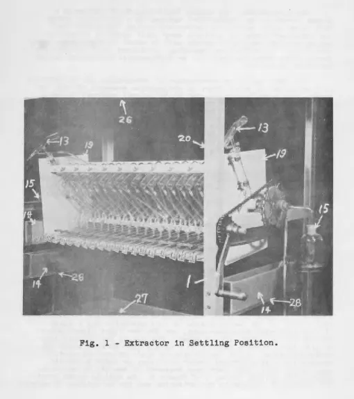
particular extractor described in detail in this report has been constructed with twenty stages; however, the design is such that any number of stages can be assembled and operated as a unit. Figures l, 2 and 3 are photographs in which the 20 stage assembly
is shown in three different positions of rotation on a horizontal
8
ISC-458
[image:10.556.22.533.61.635.2]ISC-458
9
[image:11.554.14.537.76.665.2]10
ISC-458
ISC-458 11
are essentially automatic with all sizes of this equipment. This extractor has been found to be quite useful as a research tool on a laboratory scale and the data obtained are directly applicable to larger scale separations. All parts of the apparatus that con-tact liquids have been constructed of glass or plastic.
A schematic drawing which represents the arrangement and connections for a single stage of the liquid-liquid extractor is shown in Figure 4. Rotation of this single stage clockwise through
360•
around the axis, A, completes one cycle. During this cycle the light and heavy liquid phases, not shown in this figure, move from the mixer-sett~er, 2, to the reservoirs,3
and 4, through tubes 5 and6
respectively. From the reservoirs the phases flow through tubes7
and 8 and back to mixer-settlers. The dashed sections of tubes7
and 8 indicate that in a multistage unit these tubes are actually connected to the mixer-settlers of the stages on either side of a stage such as that shown in Figure 4. The position of the light liquid take-off tube, 5, in themixer-settler tube is adjustable by movement through the plastic sleeve connection. Tube 10 is open to the outside at the curved end and serves as a breather tube. The curved section at the open end of this tube is necessary for returning to the mixer-settler tube any liquid that might get into the breather. The spout, 11, serves for adding and removing liquid from the mixer-settler tube when desired. A clamp or plug, 12, is used to close the short section of plastic tubing on this spout.
The principles of operation of the stages are further illustrated by the four positions of one stage shown in Figure 5. Suppose that the two immiscible liquid phases containing the solutes are mixed by a rocking action about the axis, A, and that they are then allowed to separate in the mixer-settler tube, as shown in
Figure 5A. The dotted area represents the liquid having the lowest specific gravity and constitutes the top phase while the cross-hatched area indicates the bottom or more dense liquid phase. When the stage is rotated clockwise through
go
degrees the position and phase separation shown in Figure 5B result. During the slow movement to this position the less dense liquid flows into the light liquid reservoir through the light liquid take-off tube. The open end of the take-off tube is at or near the limit of the liquid-liquid interface which results on approaching position B of Figure 5. Anothergo•
of rotation to the position indicated in Figure 5C then causes the heavy liquid to flow into the heavy liquid reservoir. Rotating the stage through the nextgo•
causes the liquids to flow to the opposite ends of their respective reservoirs, see Figure 5D. Finally on completing the360•
cycle the light liquid phase and the heavy liquid phase flow from these reservoirs to their proper mixer-settlers.1-' 1\)
(32mm
.
x 6inch)
( 3 2 mm. x 6 inch
21 (
25 mm
.
x 20 inch)
Fig.
4 -
Design of a Single Stage, Adjustable Open-Tube Type.( 8
mm
.
)
H en0
I
-F
\J1
[image:14.554.77.692.84.456.2]A
Fig. 5 - Positions of a Single Stage and Its Liquid Phases at Four Points during a Cycle.
c
0
H Cll 0
I
[image:15.551.16.720.17.530.2].p-\]1 (X)
...
14 ISC-458
stages in a multistage assembly for each rotation or cycle of the extractor. The pattern of flow of phases is the same for all stages of the assembly. The result of continued operation is therefore a countercurrent movement of the two liquid phases through the extractor. For each cycle of operation of a multi-stage assembly the mixing, settling, separation and countercurrent flow take place in that order and practically in phase for all of the stages.
Generally, in making fractional extractions with this apparatus~
the two immiscible solvent phases are introduced at the stages at opposite ends. The solutes to be separated are dissolved in a
portion of either phase and may be fed at any desired stage through a Y-connection inserted in the line between tube 7 or 8 and the mixer-settler tube or the stage. A feeder of one type employed for introducing a liquid phase to one of these extractors is shown at 13 of Figure 1. The three plastic troughs~ 14 of Fig~re 1~
contain the liquids to be introduced into the extractor. These troughs are located so that the reeders which rotate with the stage assembly will each pass through a trough and become filled with the proper liquid.
The product solutions are delivered from the end stages or the assembly to their receivers (15 or Figure 1). The delivery or a phase is made from the end stage reservoir to the receiver by means of a tube, 16 of Figure 6, that passes through the hollow end
shaft of the cradle, described below. This tube is connected to a delivery spout, 17, by means of a rotary joint~ 18.
SOME DETAILS OF THE EXTRACTOR DESIGN AND OPERATION
The twenty stage assembly is mounted and rotated in a cradle made of metal end plates, 19 of Figure 1, connected by four angle irons which also serve as s~age supports. Each end shaft of the cradle has a flange that is bolted to an end plate. These shafts pass through bearings that are mounted on the cross bars of the support frame, 20. The large sprocket-wheel of a 1:2 ratio chain drive mechanism is securely mounted on an end shaft. The rotation of the cradle then is effected by ~eans of the hand crank on the small sprocket-wheel which revolves on an axle mounted on the frame work. The larger wheel is a bicycle sprocket wheel with an
SECTION OF HOLLOW
END SHAFT
I
- - FROM - f - j
_IZZZZ'1III1I.~-,...r._;....
RESEfM>IRr
9
>;;;r=====.::::::-WIRE BRACKET
Fig.
6 -
Delivery Line for a Product Solution.H
C/)
0
I
-l="
\J1
[image:17.554.87.711.44.342.2]co
...
16
ISC-458is mounted on the frame engages a small arm protruding from the large sprocket-wheel on each cycle of operation. This counter does not show in Figure 1. The feeders~ 13~ are secured to the end plates by band clamps that are soldered on the ends of bolts. In Figure 1 only two of the three feeders are in view; the third feeder operates on a shorter radius and is obscured by the far end plate.
The feeders are constructed essentially of glass according to the design illustrated in detail in Figure
7.
The support arm~21~ furnishes a means for mounting the feeder. The combination of this arm and the adjustable band clamps allows proper positioning of a feeder scoop on an end plate of the extractor cradle. A cup~
221 on the feeder support arm is designed to catch liquid which
adheres to the outside of the feeder scoop and tends td-run down the support arm while in the top position. The radius of opera-tion of a feeder scoop is adjusted so that the scoop passes near the bottom of its trough. As the feeder chamber1 23~ passes below
the liquid level in its trough ·during a cycle1 liquid enters the
chamber through a hole near the leading end. On further rotation of the assembly the excess liquid overflows through the volume control tube1 241 and returns to the trough. The portion of
liquid retained in the scoop is delivered later in the cycle to the proper mixer-settler tube through the side arm, 25.
The inlet end of the feeder chamber is so designed to prevent dripping of any residual liquid from this chamber when it is
inverted during the cycle. The feeder volume control tube1 241
is open at one end and closed at the other. However1 near the
closed end and on one side there is an overflow opening. The excess liquid that flows back to the trough during rotation of the unit does so as this volume control tube approaches a vertical position in the cycle shortly after filling. This volume control tube should be turned so that the overflow opening faces the axis of rotation of the extractor for delivery of more reproducible volumes. The actual volume fed to the extractor is controlled by the adjustment of the volume control tube through the plastic sleeve joint at 9 of Figure
7.
Figure 1 shows a diagonal view of the countercurrent liquid-liquid extractor with the mixer-settlers in the settling position as shown for a single stage!Jy Figure 5A. If the stage assembly is rotated 90° clockwise from this position as observed from the sprocket end1 the light phase take-off position shown by the front
1
@
(12mm)A
Fig. 7 - Design
of
a Feeder.DIRECTION
. . - - -...MOTION
OF
H
en
0
I
+="
Vl CP
...
[image:19.549.46.692.20.527.2]18
ISC-458two product receivers occur. It is apparent that for each 360o of rotation of the assembly there is one addition of each of the liquids to the extractor and a delivery of each of the product phases from the extractor. The time necessary to complete a cycle will be discussed later, since it depends largely on factors
associated with the particular system employed.
Toe extractor support frame, 20 of Figure 1, is made of two-inch angle iron with welded construction. This stationary frame is 60 in. high, 53.5 in. across the front (front view in Figure 2) and 34 in. on the side. A wooden platform, 26, on top of this frame protects the extractor and serves as a shelf. The drip tray, 27, is 12 in. from the floor; it is made of 20 gage sheet stainless steel and is 2.5 in. deep, 30 in. wide and 50 in. long. Its purpose is to catch the liquids in case of accidental
spillage~ The three trough supports, 28, are adjustable shelves that are bolted to the frame, 20. These shelves are made of 1/4 in. stainless steel and have arms with slotted bolt holes for making proper height adjustments.
Plastic, in 1/4 in. thick sheet, was employed for construc-tion of the feeder troughs, 14. These plastic troughs are three in. wide and
4
in. high over-all. The two lower troughs are 22 in. long while the over-all length of the upper one is 17 in. Each trough has a curved floor, the radius of curvature being approxi-mately that for the arc through which the feeder scoop, 13, moves in passing through the trough. These three troughs containsupplies of the various liquids employed in the extraction. With proper flow lines from the feeders, deliveries can be made to the desired stages or the extractor. In selecting the material of construction for these troughs, full consideration must be given to possible attack on th~ material by the liquids. Some plastic materials are quite chemical resistant, readily available and easily fabricated to shape. Polyethylene appears to be a material that is quite generally useful either alone or as a coating
material. Lucoflex has been found to resist the action of most acid aqueous solutions but it is attacked by some organic solvents.
All of the glass used in this extractor is Pyrex while both polyethylene and Tygon tubing have been employed in short lengths for making connections. Tygon, which has greater flexibility, has been employed but only at certain points because it has been found to be less resistant to attack by some of the organic chemicals employed in liquid-liquid extraction studies. Since polyethylene is somewhat rigid at room temperature and quite flexible at 100°C it was softened by heating in boiling water in order to make connections. If subsequent adjustment is to be made at a plastic-to-glass connection, a bit of lubricant such as
silicone stopcock grease may be required.
ISC-458 19
Table 1
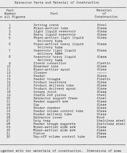
Extractor Parts and Material of Construction
Part Number
on All Figures
1 2 3 4 5 6 7 8 9 10 11 12
13
14
15
16
17
18 19 20 21 2223
2'4
25
26
2728
29
3031
32
PartDriving crank Mixer-settler tube Light liquid reservoir Heavy liquid reservoir Mixer-settler light liquid
delivery tube
Mixer-settler heavy liquid delivery tube
Reservoir light liquid delivery t~);)e_.
Reservoir heavy liquid delivery tube
Sleeve connection Breather tube
Mixer-settler spout Closure
Feeder
Feeder troughs Product receivers Product delivery tube Product delivery spout Rotary joint
Cradle end plates
Extractor support frame Feeder support arm Cup
Feeder chamber
Feeder volume control tube Feeder delivery tube
Extractor cover Drip tray
Feeder trough supports Mixer-settler side arm Mixer-settler side arm Piston
Tap-off volume control tube
Material of Construction Steel Glass Glass Glass Glass Glass Glass Glass Plastic Glass Glass Glass Plastic Glass Glass Glass Glass Steel Steel Glass Glass Glass Glass Glass Wood
Stainless steel Stainless steel Glass
Glass Glass Glass
[image:21.549.53.490.80.605.2]20 ISC-458
A PROCEDURE FOR STARTING THE EXTRACTOR
A systematic procedure for starting a countercurrent liquid-liquid separation with this extractor is required for efficient operation. The connections should first be made between the
feeders and the desired mixer-settler tubes and between the proper reservoirs and the receivers to give the required number of stages
and proper flow. Each feeder and trough combination is positioned
to give proper movement of the feeders through the troughs. In
the particular examples that are presented here for the separation of two inorganic compounds, an aqueous feed is introduced at some intermediate stage while an aqueous scrub and an immiscible, less dense, organic liquid enter at stages at opposite ends of the extractor. The two product phases are discharged according to countercurrent flow at the reverse ends.
The selection of flow rates (volumes of liquids introduced into the extractor per cycle) is made on the basis of single stage or other data and the extractor cradle is placed in approximately
the position indicated in Figure
3.
Measured flow-rate volumesof the liquids are placed in the chambers of their respective
feeders. The feeder volume control tubes are then adjusted down
to deliver only these volumes to the extractor as the cradle is
turned slowly clockwise. The rotation is continued to·a position
for complete charging with the aqueous phase. This position is
attained when the mixer-settler tubes point up with their spout ends at about 30° from horizontal.
At this new position the closures, 12, (see Figure 4) are released and the required volumes of the aqueous phase for the stages are added to the mixer-settler tubes through the spouts, 11.
Sometime~ the aqueous scrub liquid serves for all of these aqueous
phase additions in starting up the extractor. The extractor
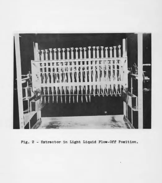
assembly is then further rotated clockwise to the position indicated
in Figure 2. Here the volume control tubes are adjusted down in
the mixer-settlers until their open ends are slightly above the
level of the aqueous phase, as shown in Figure 5B. The cradle is
then slowly rotated cOunterclockwise back to the position employed above where additions of aqueous phase were made to the stages. At this position the required volume of organic liquid is added
to the stages through the spouts, 11. These spouts are then closed.
The feed troughs are then filled with their respective liquids. The cradle is now slowly rotated about 30° counterclockwise to
the position represented in Figure 1. The mixer-settler tubes
should contain at this time the proper amounts of the liquids for starting continuous operation.
Mixing of the phases in the mixer-settler tubes is next achieved by an oscillatory movement of the cradle through a total arc or roughly 40° about the position shown in Figure 1. The
phases are then allowed to ~eparate with the mixer-settlers in a
ISC-458 21
in a clockwise direction according to the sequence of operation described for passing through the positions illustrated by Figure 5 completes the first cycle. The feeding and delivery of liquids are essentially automatic during subsequent cycles. All further rotations of the assembly are made in a clockwise direction except during the mixing operation for each cycle.
If the stage assembly is initially charged with feed solution at only the feed stage, a number of cycles will be required before delivery of solutes will be observed. The liquid-liquid extraction system ordinarily does not closely approach a steady state of
operation until a number of cycles have been completed. Consequently, it will usually be desirable during the early cycles of operation to make minor readjustments of the positions of the light liquid take-off tubes in the mixer-settlers. It is essential that each of these take-off tubes be kept in such a position so that a small amount of the light liquid phase flows to the heavy liquid reservoir and not vice versa.
SEPARATION OF SOME INORGANIC SALTS
Countercurrent liquid-liquid extractors are employed in this Laboratory largely for the separation and purification of inorganic salts. By use of extractors of the type described in this article a number of compounds with purities adequate to serve as base
materials for the preparation of standards for spectrographic analysis have been obtained in quantity. Although other mixtures have been studied, some experiments on separations or zirconium from hafnium and of tantalum from niobium will be presented to demonstrate practical use of these extractors. In each case the operating conditions employed in the multistage extractions were selected from single stage data.
1. Separation of Zirconium from Hafnium
It was reported earlier by workers in this Laboratory (28) that tributyl phosphate preferentially extracts zirconium from an aqueous nitric-hydrochloric acid solution containing both hafnium and zirconium. Two countercurrent liquid-liquid extractions employing this system are reported here; the first was carried out on an intermediate composition mixture which contained about equal proportions by weight of the two elements while the second extraction employed a mixture that was primarily hafnium con-taining only a few per cent of zirconium.
22
ISC-458
for at least two hours the resulting oxides were assayed for
relative percentages of zirconium and hafnium with minor impurities disregarded. Analytical data are reported on the basis of hafnium and zirconium elements:only; i.e., the sum of the hafnium and the zirconium contents equals 100 per cent. The spectrographic
methods of Fassel and co-workers (29) were employed for analyzing these mixtures containing hafnium and zirconium.
a. Separation of Zirconium from Hafnium in An Intermediate Composition Mixture
The separation of zirconium from hafnium employing a mixture in which both are present in approxmatcly equal amounts is of very limited practical interest; however, such a separation is presented here as an example of the performance of this extractor.
A mixture of hafnium and zirconium oxychlorides containing
43
w/o hafnium (and57%
zirconium) relative to the total hafnium and zirconium content was dissolved .1n nitric acid. The result-ing solution, or aqueous feed, was6.75
molar in nitric acid and contained the equivalent of 172 g. of the combined oxides per liter. Twenty-five milliliters per cycle of this feed solution was introduced at stage14
of the 20 stage extractor shown in Figure 1.The aqueous scrub liquid which consisted of
6.75
molar nitric acid was introduced at stage one. Its flow rate was 15 ml per cycle. A mixture of 40% by volume of dibutyl ether in tributyl phosphate constituted the organic phase. This solution was introduced at stage 20 at the rate of 40 ml per cycle.Operation of the extractor with these solutions was started according to the procedure described above. The products from every tenth cycle of operation were analyzed for hafnium and zir-conium to determine the approach to essentially steady state. These analyses indicated that about 100 cycles were required to obtain this steady state operation. After 130 complete cycles of operation the extraction was discontinued and the liquids collected from each of the stages to obtain stagewise analytical data for the phases at steady state. A material balance, calculated on the average volumes, concentrations and analyses of the two product phases from the last 30 cycles indicated that about 50 w/o of the total oxides of hafnium and zirconium was delivered by the organic product phase.
ISC-458 23
Table 2
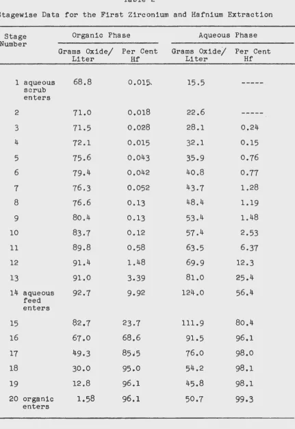
Stagewise Data for the First Zirconium and Hafnium Extraction
Stage Organic Phase Aqueous Phase
Number
Grams Oxide/ Per Cent Grams Oxide/ Per Cent
Liter Hf Liter Hf
1 aqueous 68.8 0 .015. 15.5
---scrub enters
2 71.0 0.018 22.6
---3 .71.5 0.028 28.1 0.24
4 72.1 0.015 32.1 0.15
5 75.6 0.043 35.9 0.76
6 79.4 0.042 40.8 0.77
7 76.3 0.052 43.7 1.28
8 76.6 0.13 48.4 1.19
9 80.4 0.13 53.4 1.48
10 83.7 0.12 57.4 2.53
11 89.8 0.58 63.5 6.37
12 91.4 1.48 69.9 12.3
13 91.0 3.39 81.0 25.4
14 aqueous 92.7 9.92 124.0 56.4
feed enters
15 82.7 23.7 111.9 80.4
16 67.0 68.6 91.5 96.1
17 49.3 85~5 76.0 98.0
18 30.0 95.0 54.2 98.1
19 12.8 96.1 45.8 98.1
20 organic 1.58 96.1 50.7 99.3
[image:25.556.55.486.73.699.2]24 ISC-458
apparent from these stagewise data that the oxide concentrations were at maxima in both the organic and aqueous phases at stage l4p
the feed stage. It is to be noted that in general the stagewise
percentages of hafnium and zirconium progressively changed through the extractor. The minor deviations from this trend were probably caused by sample contamination or operative errors in analysis. This recovery of two high purity products from a binary mixture of roughly equal amounts of closely related compounds demonstrates the adaptability of this extractor to separations by countercurrent liquid-liquid extractions.
b. Separation of Small Amounts of Zirconium from Hafnium
Although removal of small amounts of zirconium from a mix-ture that is largely hafnium is not considered important indust-rially, it is employed here as a further demonstration of
the applicability of these extractors to ~iquid-liquid
purifica-tion processes. In this second multistage extraction only 15
stages of a 20 stage extractor were employed for making the
separation. The liquid-liquid system used to effect the removal
of the zirconium was the same as that employed in the multistage extraction above except for concentrations and flow rates.
The analysis of the inorganic salt mixture employed in pre-paring the aqueous feed solution gave about 3.2 w/o zirconium and
96.8% hafnium relative to their total weight. The feed contained
the equivalent of 380 g.of the combined oxides per liter and was 3.16 molar in nitric acid. "Twenty milliliters of feed was added at stage 7 for each cycle of operation.
A 3.14 molar nitric acid solution constituted the aqueous scrub liquid for this multistage extraction. For each cycle of operation 5.0 ml of this aqueous scrub was added at stage one. The organic phase, introduced at stage 15 at a rate of 25 ml
per cycle, was a solution consisting of 40 volume per cent dibutyl
ether and 60 vol.ume -per cent tributyl phosphate. This organic
solution was also 2.68 molar in nitric acid.
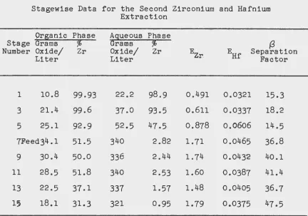
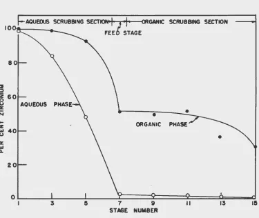
Analysis of the products from every tenth cycle showed that essentially steady state conditions were reached at about the 40th cycle. The extraction was discontinued after 100 complete cycles and the phases from the odd numbered stages were analyzed. These stagewise data appear in Table 3 while Figure 8 indicates the variation or these analyses with stage number.
It is apparent from Table 3 that the aqueous phase product from stage 15 was about 99% hafnium while the organic phase product
from stage one was 99.93% zirconium. Approximately 70% by
weight of the total zirconium containing only 700 ppm hafnium was
recovered in the organic phase product. The loss or hafnium in
this organic product amounts to less than 0.002% or the total
hafnium. Most or the zirconium remaining in the aqueous product
ISC-458 25
obtained by a subsequent multistage extraction employing similar conditions. However, by properly varying the operating conditions, a more nearly quantitative separation could likely be affected in only one multistage extraction.
Table 3
Stagewise Data for the Second Zirconium and Hafnium Extraction Stage Number 1 3 5 Organic Grams Oxide/ Liter 10.8 21.4 25.1 7Feed34.1
9 30.4
11 28.5
13 22.5
15 18.1
Phase
%
Zr 99.93 99.6 92.9 51.5 50.0 51.8 37.1 31.3 Aqueous Grams Oxide/ Liter 22.2 37.0 52.5 340 336 340 337 321 Phase%
Zr98.9
93.5 47.5 2.82 2.44 2.53 1.57 0.95 E Zr 0.491 0.611 0.878
1. 71
1.74 1.60 1.48 1.79 {3 Separation Factor
0.0321 15.3
0.0337 18.2
0.0(506 14.5
0.0465 36.8
0.0432 40.1
0.0387 41.4
0.0405 36.7
0.0375 47.5
In the organic scrubbing section of the extrac.tor, or stages 15 to seven inclusive, the relative flow rates were approximately five volumes of the aqueous phase to four volumes of the organic phase. The relative flow rates in the aqueous scrubbing section, stages one to six inciusive, were about four volumes of the
organic phase to one volume of the aqueous phase. Figure 8
[image:27.553.52.484.129.432.2]::1
=»
26
z
600
u
D:
N
....
z
"'
uD:
"'
CLISC-458
AQUEOUS SCRUBBING SECTION+
I?
"i•
CRGANIC SCRUBBING SECTIONFEE STAGE
•
ORGANIC
oL---~---L----~==~====~====4===~
I 7 13 15
STAGE
[image:28.553.58.433.141.457.2]ISC-458 27
zirconium delivered but the amount of zirconium recovered would have been less. Similarly a relatively larger volume of the
organic phase would have increased the recovery of zirconium while decreasing its purity. Changes in the number of stages employed and in the position of the feed stage as well as variations in relative flow rates would have effectively altered the separations obtained by this extractor with this particular liquid-liquid system.
The distribution ratios for zirconium and hafnium, Ezr and EHf respectively, and their separation factors also appear ·~n
Table
3.
The distribution ratio here is the ratio of the total concentration of a constituent in the organic phase to its total concentration in the aqueous phase. The separation factor is defined as the ratio of the two distribution ratios for a stagein equilibrium. Large separation factors are desirable for making separations but proper mass distribution between the phases must also be considered.
It can be seen from Table 3 that the separation factors for the liquid-liquid system employed have considerably different
values in the organic and aqueous scrubbing sections of the extractor. Since the acid concentrations in the respective solutions delivered to the extractor and in the corresponding solutions delivered from the extractor were essentially the same, it is assumed that there was no appreciable variation of acid concentration in either phase throughout these sections. The distribution ratio for zirconium in the organic scrub section appears then to be influenced by the presence of large amounts of hafnium. This particular extrac-tion of zirconium from hafnium illustrates some of the operaextrac-tional data which can be readily obtained by employing an extractor of the design described here.
2. Separation of Tantalum from Niobium
t
Earlier work in this Laboratory (30) showed that tantalum could be readily separated from niobium by extractions involving their aqueous hydrofluoric acid solutions and certain immiscible organic liquids. Since this system contained free hydrofluoric acid it was not practical to use glass equip~ent for continued separation work. Therefore, other effective liquid-liquid systems for the separation of tantalum from niobium were developed in an effort to obtain conditions of extraction that would permit prolonged use of glass equipment.
It was found that tantalum could be easily extracted from an amine-hydrofluoric acid salt solution containing both niobium and tantalum. The addition of the amine to the hydrofluoric acid solution forms this salt and markedly reduces the attack of the solution on glass. A multistage extraction employing this
28
ISC-458The aqueous feed solution was prepared by dissolving a
mix-ture of niobic and tantalic acids in a minimum amount of concentrated hydrofluoric acid. After dilution with water this solution
con-tained the equivalent of 130 grams of niobium and tantalum pentoxides per liter. A sodium hydroxide titration of an aliquot of this
solution indicated acid equivalent to 4.06 moles per liter. Suffi-cient phenyl ethyl ethanolamine was added to the hydrofluoric acid solution of niobium and tantalum to saturate the solution. The resulting solution which h~d a pH of about
5
and a concentration equivalent to about 110 grams of niobium and tantalum pentoxide per liter constituted the feed solution for the multistage extrac-tion. The oxide was composed of about 51% tantalum oxide and 49% niobium oxide relative to their total pentoxide weight. For each cycle of operation 10.0 ml or this aqueous feed solution was added at stage four. Only 10 stages of a 20 stage extractor were used in this experiment.The aqueous scrub s0lution was diluted hydrofluoric acid which had been saturated with phenyl ethyl ethanolamine giving a fluoride salt concentration or about 0.5 molar and a pH value of about
4.
Five milliliters or this solution was added per cycle at stage one. Pure diethyl ketone constituted the organic phase in this extrac-tion and was introduced at stage ten at the rate of 30 milliliters per cycle.
The product phases for every fifth cycle of operation were analyzed for their total oxide contents and for relative percentages of the niobium and tantalum oxides. After
55
complete cycles the process was discontinued, the liquids collected from the stages and oxide analyses performed on both phases from each stage. In these analyses excess ammonium hydroxide was added to the aqueous and organic phases to precipitate niobium and tantalum. Acetone was also added to the organic phase to facilitate the precipitation and filtration. The precipitates were calcined at6oo•c
for at least two hours to form the pentoxides. The percentages of niobium and of tantalum oxides are expressed relative to their total oxide contents in the samples with all impurities disregarded. For samples containing between two and98%
tantalum oxide an x-ray fluorescence technique (31) was employed, while for less than two and above98%
tantalum oxide the spectrographic methods of Fassel and Krotz (32) were used.
ISC-458
29
The cycle analyses showed that for the first 50 cycles or operation only about 100 ppm niobium oxide was present in the tantalum oxide from the orgaiic product. However, the stagewise data of Table 4 indicate that the oxide delivered in the organic phase from stage one should have contained 0.054% (540 ppm)
niobium oxide. A new supply or aqueous scrub was employed for the last few cycles of operation and it is possible that this scrub contained a small amount or niobium. A slight contamina-tion of the scrub with niobium would also explain the lower percentages of niobium in both phas8s in stage two with higher niobium percentages in stage one. Since the laboratory is also used for other problems involving these elements this contamina-tion is not unlikely. This contamination effect has been met previously in other work here in attempts to prepare very pure compounds; however, when special precautions were taken on recheck experiments it was found possible to eliminate these minor con-taminations.
The data in Table 4 also show that the maximum oxide concentra-tions of both the aqueous and the organic phases were in stage four, the feed stage. It is also apparent that very little material was extracted into the organic phase in stages nine and ten. The
over-all material balance, based on average analyses, concentrations and volumes of products indicated that the organic product phase from stage one and the aqueous product phase from stage ten con-tained about 51% and 49% respectively of the total weight as tantalum and niobium oxides.
Figure
9
shows the variation of the oxide composition, expressed as niobium pentoxide percentage, with stage number for both theorganic and aqueous phases. It is apparent from the data that very little niobium transferred to the organic phase in any stage. Since the large variation in niobium percentage in the aqueous phase is due mainly to the distribution of tantalum to the organic phase, the separation then depends essentially on the
sel~ctive transfer or tantalum. Consequently, the prime operation
factor in this separation is the organic scrubbing or tantalum from the aqueous feed solution.
In this extraction an equivalent or approximately a 50-50 mixture of niobium and tantalum oxides was quantitatively separated
into a tantalum oxide fraction containing 100 ppm niobium pentoxide and a niobium fraction spectrographically free or tantalum.
This experiment further demonstrates the possibilities or this extractor for obtAining useful data on liquid-liquid extractions. For large scale separations of tantalum and niobium more
30 ISC-458
Table 4
Stagewise Data for the Niobium and Tantalum Extraction
Organic Phase Aqueous Phase
Stage Number 1 2 3 4 5 6 7 8 9 10 Feed Grams Oxide/ Liter 19.0 15.8 18.8 19.8 5.27 2.24 1.20 0.97
·0 .038
0.12
*Insufficient sample for NbfO~ outside range for Va u s for stages
8, 9,
0.054 0.030 0.17 0.24 0.50 1.42 * * * * Grams Oxide/ Liter 10.8 40.9 47.2 51.2 47.0 40.2 38.4 37.5 36.1 37.7 0.84
o.p8o
1.78 64.0 72.3 90.0 97.5 99.1 <99.97 <99.97analysis by x-ray fluorescence; per cent the spectrographic calibrations employed. and 10 estimated at above 2.5% Nb205 •
MODIFICATIONS OF Th~ EXTRACTOR
[image:32.545.49.486.83.446.2]ISC-458
31
I• FEED
STAGE
ORGANIC PhASE
0&---~--~==~==~==~==~~L---L-~
2 3 4 ~ 6 7 8 9 10
STAGE NUMBER
[image:33.554.47.419.129.415.2]VJ 1\)
( 2 5 mm. x 6 inches)
2J(20mm. x 20inches)
Fig. 10 - Design of a Single Stage, Adjustable Piston Type.
H Cll
c
I
-F \J1
[image:34.551.159.674.115.458.2]ISC-458 33
If we substitute for the single stage of Figure 5B~ the design
of stage shown in Figure 10, then the light liquid phase would be delivered from the mixer-settler tubes through the side arm, 29. The side arm, 30, is employed for delivery of the light liquid phase
when the volume of the heavy liquid phase is small. For the
extrac-tor size presented here a volume of about five milliliters or less
of the heavy phase requires the use of the side arm~ 30. The side
arm which is not in use is usually closed by a glass or plastic
plug. It is evident from Figure 10 that for the use of side arm
30 an interchange of positions of plug and end connection of tube
5 is required.
The piston, 31, is adjusted through its sleeve joint, 9. This
adjustment regulates the position of the liquid-liquid interface
for proper flow of the light liquid phase to its reservoir. For
small diameter (less than 24 mm) mixer-settler tubes this
piston-type adjustment usually affords a better control of delivery
of the phases to the prope~ reservoirs; however, for larger
(greater than 24 mm) diameter mixer-settlers 1 the. ad.ju$'table<A::>lpen-tube
type shown in Figure 4 has advantages.
Figure 11 shows a 20 stage piston--type liquid-liquid extractor
in a position corresponding to that of the cten-.tube type extractor
shown in Figure
3.
The procedure for starting and operating thesetwo extractors ie essentially the same. The first hafnium-zirconium
extraction described above was carried out in the ~n-t.ube type
extractor while for the second hafnium-zirconium extraction and for the niobium-tantalum extraction the piston type extractor was used.
Occasionally in liquid-liquid extraction work it is desirable
to remove a portion of a phase at some intermediate stage. A
special reservoir designed for th~ extractor permits this removal.
The details for this tap-off reservoir appear in Figure 12. It
can be seen in this figure that a tap-off volume control tube» 32,
is inserted at the delivery end of the reservoir. This tap-off
deviee consists essentially of a tube which by a sliding adjustment through its sleeve connection regulates the amount of liquid
removed from the reservoir and the extraction system. A portion
of either phase can be removed from any desired stage by merely substituting this special reservoir in place of a regular reservoir. The liquid which is removed from the extractor by means of a tap-off reservoir can either be delivered into a receiver collecting a
product phase or into a special receiver. This device can be employed in extractions involving what is often referred to as
reflux. The reflux takes place as that portion of the product
34
ISC-458
[image:36.549.33.530.52.673.2]TO
PRODUCT
RES~RVOIRFig. 12 - Tap-Off Reservoir.
( 3
or
4)
7
or
8)
H
(I)
0
I
+=" V1
co
UJ
[image:37.554.83.687.133.334.2]ISC-458
DISCUSSION
The extractor presented here has been demonstrated to give efficient operation inerrecting separations by liquid-liquid
systems. An analysis or the sequence or events in connection with the movements or the phases through the extractor shows that the operation and results are effectively those of a true multiple-contact countercurrent extractor. Since a phase portion moving into any one stage does not contact the portion of the other phase which earlier in the same cycle moved out of that stage, there arises a question as to the actual interpretation of the extraction pattern.
To clarify this matter, let us suppose that one employs all 20 stages of this extractor, and that the aqueous phase enters only at stage number 1 and leaves from stage 20, while the immiscible organic phase enters at stage 20 and leaves from stage 1. During the operation, each portion of aqueous phase that enters will, on succeeding cycles, be mixed with a portion of the organic phase in each of the 20 stages. Similarly each portion of the organic phase that enters the extractor will contact a portion of the aqueous in each stage. It is to be noted, however, that at any one time the portions of the aqueous and the organic phases in the odd numbered stages will not, on passing through the extractor, contact those portions of the opposite phases that are at that time in the even numbered stages and vice versa.
Consider a portion of aqueous phase that is at one time in stage number 1. This portion will contact the portions of organic phase that are at this time in stages
3,
5, 7, 9, 11,13,
15, 17 and 19 when on further operation this particular portion of aqueous phase moves to stages 2,3, 4,
5,6, 1, 8,
9 and 10 respectively. The portions of organic phase to be contacted by this particular portion of aqueous phase when it passes through stages 11 to 20 inclusive are not yet in the extractor when this portion of aqueous phase is in stage number 1.ISC-458 37
to be discussed in a later paper operates with all portions or the organic phase contacting all portions of the aqueous phase that pass through in a multicontact countercurrent liquid-liquid extraction. For similar systems the stagewise data have been found to be essentially identical when employing either type extractor.
The liquid-liquid extractors presented here can give effective separations and are applicable to the study of many liquid extrac-tion problems. Larger capacity extractors of this type are in use in this Laboratory for preparing pure materials in quantity. Extrac-tors of this design could also be constructed on a smaller scale for laboratory table use with smaller amounts of liquids. The lower limit of size would be determined by interfering capillary effects of the liquids in the tubing employed.
The design of this extractor permits its operation to be interrupted repeatedly at the convenience of the operator without losing continuity in an extraction. This allows samples to be taken of the phases in the stages and permits alterations in the extraction as desired.
In operation or this extractor it makes no difference which phase has the greater specific gravity. Extraction systems have been employed in this Laboratory in which sufficient carbon tetra-chloride was added to tributyl phosphate to make the specific gravity of the organic phase greater than its contacted aqueous phase. The extractor functioned effectively in making separations with this type of system.
The phase separation time is a factor to be considered in the operation of any liquid-liquid extractor. For the extractor
presented here it is especially important in determining the time required for a cycle or operation. Organic diluents have been found to be useful for decreasing the phase separation times.
Any liquid-liquid system that upon mixing forms an emulsion which is not easily broken would be impractical to use in this extractor. Since phase separation time is usually the most time consuming step$ its control is very important when considering the rate of product delivery or time required to carry out an experiment. The use of a 40 volume per cent dibutyl ether and 60 volume per cent tributyl phosphate organic solution for extracting zirconium from hafnium in a 6.0 molar nitric acid aqueous phase changed the phase separation time from 90 sec. for pure tributyl phosphate to 30 sec. for the mixed organic solvent phase. The initial aqueous and organic phases were mixed to about the same extent in both experiments. With a 30 sec. phase separation time a cycle can be completed easily in two minutes.
38 ISC-458
ACKNOWLEDGMENTS
The authors are indebted to Dr. Morton Smutz for a critical
reading of the manuscript. In addition, the authors wish to thank
J. V. Kerrigan, R. Jensen and E. Murray for their assistance in design modifications and in extraction operations. The coopera-tion of the glassblowing shop, metal shop, drafting and spectro-graphic sections in this work is also greatly appreciated.
1 .
2.
3.
4.
5.
6.
8.
9.
REFERENCES
D. F. Peppard~ J. F. Faris, P. R. Gray and G. W. Mason, J. Phys.
Chern. 57, 294 (1953).
B. Weaver, F. A. Kappelmann and A. C. Topp, ORNL-1408 (1952).
A. C. Topp, ORNL-1409 (1952).
J. Bochinski, M. Smutz and F. H. Spedding, ISC-348 (1953).
L. C. Craig, J. Biol. Chern., 150, 33 (1943).
L. C. Craig, G. H. Hogeboom, F. H. Carpenter and V. DuVigneaud,
J . Biol. Chern., 168, 665 (1947).
R. E. Cornish, R. C. Archibald( E. A. Murphy and H. M. Evans, Ind. Eng. Chern., 26, 397 (1934J.
Y. Sato, G. T. Barry and L. C. Craig, J. Biol. Chern., 170, 501 (1947).
E. H. Ahrens and L. C. Craig, ibid., 195, 299 (1952).
10. Ibid., 195, 763 (1952).
11. A. J. P. Martin and R. L. M. Synge, Biochem. J., 35, 91 (1941).
12. C. E. White and H. Rose, Anal. Chern., 25, 351 (1953).
13. E. M. Larsen and G. Terry, J. Am. Chern. Soc., 75, 1560 (1953).
14. R. L. VonBerg and H. F. Wiegandt, Chern. Eng., 59, No.
6,
189(1952).
15. G. H. Morrison, Anal. Chern., 22, 1388 (1950).
16. L. C. Craig, ibid., 21, 85 (1949); 22, 61 (1950); 23, 41 (1951);
ISC-458 39
17. H. M. Irving, Quart. Revs.,
2,
No. 2, 200 (1951).18. U. S. Marella and N. Poffenberger, Ind. Eng. Chern., 42, 1021 (1950).
19. E. L. Compere and A. Ryland, Ind. and Eng. Chern., 45, 1682 (1953).
20. L.
c.
Craig, J. Biol. Chern., 155, 519 (1944).21. L.
c.
Craig ando.
Post, Anal. Chern., 21, 500 (1949).22. L.
c.
Craig, W. Hasmann, E. H. Ahrens and E. J. Harfenist, ibid.,23, 1236 (1951).
23. G. H. Lathe and
c.
R. Ruthen, Biochem. J., 49, 540 (1951).24. M. R. Fenske and B. R. Tegge,
U.
s.
Pat. 2,580,010.25. E. M. Nadel and F. Highhouse, Chemist Analyst, 43, No. 1, 25 (1954).
26. K. A. Varteressian and M. R. Fenske, Ind. and Eng. Chern., 28, 1353 (1936).
27. H. A. Wilhelm, (a) ISC-155 (Jan. 24, 1951), (b) ISC-144 (May 1, 1951), (c) ISC-203 (March 31, 1952).
28. H. A. Wilhelm, K. Walsh and J. V. Kerrigan, Patent Application
Serial Number 382,496, (August 18, 1953).
29.
i
a) V. A. Fassel and C. H. Anderson, J. Opt. Soc. Am., 40, 7421950).
-b) V. A. Fassel and L. Gray, forthovming publication from this Laboratory.
30.
H.
A. Wilhelm, L. Cass and J. V. Kerrigan, ISC-220 (March 10,1952).
31. W. J. Cambell and H. F. Carl, Anal. Chern., 26, 800 (1954).
32. V. A. Fassel and L. Krotz, forthcoming publication from this Laboratory.