Haptics for Multi-Fingered Palpation
Min Li, Shan Luo, Lakmal D. Seneviratne, Thrish
Nanayakkara, Kaspar Althoefer
Dept. of Informatics, Centre for Robotics Research King’s College London
London, UK [email protected]
Prokar Dasgupta
MRC Centre for Transplantation, DTIMB and NIHR BRC King’s College London
London, UK
Abstract— During open surgery, surgeons can perceive the locations of tumors inside soft-tissue organs using their fingers. Palpating an organ, surgeons acquire distributed pressure (tactile) information that can be interpreted as stiffness distribution across the organ – an important aid in detecting buried tumors in otherwise healthy tissue. Previous research has focused on haptic systems to feedback the tactile sensation experienced during palpation to the surgeon during minimally invasive. However, the control complexity and high cost of tactile actuators limits its current application. This paper describes a pneumatic multi-fingered haptic feedback system for robot-assisted minimally invasive surgery. It simulates soft tissue stiffness by changing the pressure of an air balloon and recreates the deformation of fingers as experienced during palpation. The pneumatic haptic feedback actuator is validated by using finite element analysis. The results prove that the interaction stress between the fingertip and the soft tissue as well as the deformation of fingertips during palpation can be recreated by using our pneumatic multi-fingered haptic feedback method.
Keywords-finite element analysis; haptic feedback; multi-fingered palpation; tumor identification
I. INTRODUCTION
The hands of surgeons play an important role, since they are indispensible tools to acquire tactile information for the identification of tumors during open surgery. The accurate localization of an embedded tumor is critical to ensure that the entire tumor is removed and healthy tissue is spared as much as possible. Areas that are stiffer than the surrounding tissue are indicative for the presence of tumors. During Minimally Invasive Surgery (MIS), “instrument palpation” can be conducted: the organ surface is prodded by a long metal rod inserted through the trocar to detect hard inclusions. Although Robot-assisted Minimally Invasive Surgery (RMIS) has many benefits over traditional MIS, such as enhanced 3D vision and an improvement of dexterity, the sense of touch is still missing, which makes intra-operative tumor identification difficult. Instrument palpation cannot be conducted in RMIS where direct haptic feedback is not available. Researchers tried to implement instrument palpation methods using a RMIS system
equipped with force feedback [1]. However, this type of palpation procedure is quite time consuming [1]. In particular, instrument palpation is time consuming and not effective for small and deeply buried tumors since tactile information is missing [2]. Low-cost visual tactile cues can be introduced to compensate for the lack of tactile sensation - methods whereby material property distribution graphically overlaid over visual feeds from the operating site are presented [2], [3] are presented. Nevertheless, graphically overlaying real-time stiffness data over the camera image can negatively impact on the clarity of the perceived image. Tactile actuators, which provide the user with tactile feedback as experienced during palpation, has been introduced for tumor identification in MIS; as for instance described in [4]. However, its current application is limited by the complexity and high cost of the required tactile actuators. In order to reduce the control complexity introduced by using the tactile feedback devices, a multi-fingered palpation feedback method is proposed here. Compared with tactile haptic methods as, for example, described in [5], [6], the actuator elements in our multi-fingered palpation haptic system are much reduced. This paper describes a multi-fingered palpation haptic device with three pneumatic haptic feedback actuators and shows its feasibility experimentally.
II. RELATED WORK
A. Area-based single-fingered palpation
The texture and material properties of an object can be perceived by obtaining distributed pressure values during mechanical probing [7]. Currently, tactile feedback display has several types of techniques including tactile pin display [5], vibrotactile [11], pneumatic activated tactile display [6], microfluidic activated tactile display [12], surface acoustic waves [13], focused ultrasound [8], electrorheology [14] and electrotactile [15]. Two main simulation types are available for tumor identification using tactile feedback devices: movable components and materials with variable stiffness. Providing distributed pressure (tactile information) to one finger during palpation has been conducted in [5], [6], [16]. Pneumatic tactile displays use air pressure to displace the skin, either by discharging air directly through nozzles against the skin or inflating conformable tactors. Kim et al. [16] tested a pneumatic approach using an array of open nozzles to discharge compressed air directly against the skin. Culjat et al. This research is partially supported by the European Commission’s
fingered palpation, Proceeding of IEEE International conference on System, Man and Cybernetics, 2013, 4184-4189 [6] developed a pneumatic balloon tactile display, which can be
easily attached to existing commercial robot-assisted surgery systems such as da Vinci. Klein et al. [63] described a tactile actuator array using electrorheological fluid. Liu et al. [64] described a design of a single MR fluid-based tactile element. Instead of only provide tactile feedback, Kim et al. [5] combines tactile pin display with kinesthetic feedback in a palpation simulator. The experimental results show that compared to the point palpation, the area-based single-finger palpation provides the user with more precise perception of the shape and softness of the embedded nodules. The development of tactile devices is hampered by the limited understanding of the human tactile receptors. The lack of commercially available tactile devices limits current application of area-based palpation simulation.
B. Multi-fingered palpation
Multi-fingered palpation is more common than single-fingered palpation in real practice. There are some reports about multi-finger palpation simulation. In 1990s, Rutgers Master II force feedback glove, which can provide force feedback up to 16 N to each finger, was used in palpation simulators. It was applied on training of knee palpation [17] and for abdominal palpation for liver tumor detection [18]. Pneumatic actuators are used to apply forces to all of the fingertips except for the pinky finger. It is light weighted (only 80 grams). However, the glove limits the range of motion of the fingers because of the placement of the cylinders. Another example is the haptic Interface Robot (HIRO) device. It was used for breast palpation simulation [19]. The device was developed by Kawasaki et al. [20]. It consists of a force actuated 6-DOF arm and 3 fingers with 3-DOF force output. And it was upgraded to the five fingered HIRO III device [21]. However, the price is relatively high.
III. MULTI-FINGERED PALPATION SYSTEM
Our actuator contains a deformable surface, a non-deformable substrate with a cylindrical hole, air tubing and a pressure-controllable air supply. When it is in use, a finger of the user is in contact with the surface of the actuator and the air pressure inside the actuator replicates the soft tissue stiffness. Higher air pressure represents stiffer tissue regions while lower pressure represents softer regions. At the same time, the actuator creates a deformation of the user’s fingertip and gives an impression of the indentation when palpating a soft organ. During palpation, for the same force applied, the indentation depths are different between a harder area and a healthy soft tissue area. Thus, the deformations of the practitioner’s fingertip are different. Fig. 1 shows a pneumatic haptic feedback actuator, which consists of four main parts–a soft silicone layer, a silicone rubber film (SILEX Ltd., HT6240, 0.25 mm thick, tensile strength 11 N/mm2, elongation at break 440%, tear strength 24 N/mm), a PDMS substrate (GE RTV615) with a cylindrical cavity (4 mm in diameter), and air tubing. Air is injected into the cavity of the PDMS substrate and causes the silicone rubber film to inflate. The upper soft silicone layer (RTV6166 A : B=4 : 6, thickness: 3 mm) is used to simulate the touch impression of soft tissue and limit the deformation of the silicone rubber film. The silicone rubber
film and the substrate are bonded with translucent silicone rubber adhesive E41.
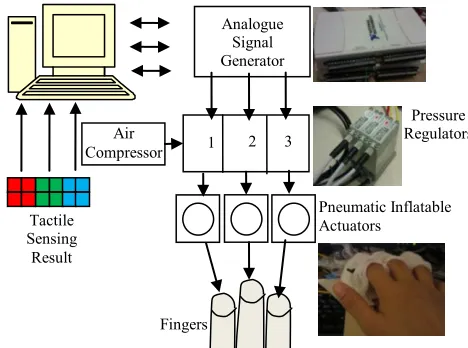
[image:2.612.333.547.203.304.2]Fig. 2 shows the block diagram of the control of the pneumatic haptic feedback actuator. Data from the tactile sensor elements are divided into three groups, whose average values are used as the input of the system. According to the tactile sensing input (e.g. from the tele-manipulator), the corresponding three channels of air pressure values are calculated. Two NI DAQ cards (USB-6211) are used as analogue signal generators for the pressure regulators (SMC ITV0010). The pressure regulators inflate each of the actuators with proportional pressures ranging from 0.01 to 0.1 MPa.
Figure 1. A pneumatic haptic feedback actuator, shown in (a); schematic diagram of components, (b).
Figure 2. Multi-fingered palpation system.
IV. VALIDATION AND RESULTS
A. Deformation response of the actuators
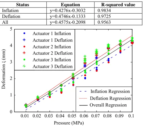
The deflection response of the actuators was examined under different inflation pressures ranging from 0.01 MPa to 0.1 MPa. The deflection of the actuators (without the silicone layer mounted) was measured by using a digital calliper (Resolution: 0.01 mm, accuracy +/- 0.02 mm). Tests were repeated five times. Fig. 3 shows a non-activated and an activated pneumatic haptic feedback actuator. Fig. 4 and Table 1 show the test results of actuator deformation (ξ) testing. The accuracy of the linear trend lines are indicated by the correlation coefficients, confirming the linear relationship between the vertical actuator deflection and the inflation pressure.
(b) Silicone
Rubber Film
PDMS Substrate Air Tubing
Cavity Inside Silicone Layer
(a)
Analogue Signal Generator
Pneumatic Inflatable Actuators
Air Compressor
Pressure Regulators 3
2 1
Tactile Sensing
Result
[image:2.612.330.564.340.514.2]B. FE Modelling
According to the design, the perception of stiffness comes from the air pressure inside the pneumatic actuator, and the deformation of fingertip caused by the inflation of the actuator gives an impression of the indentation when palpating a soft organ. The stress and deformation of the fingertip caused by palpation are compared with them caused by the actuator using finite element (FE) modeling.
[image:3.612.71.264.155.223.2]Figure 3. (a): Non-activated pneumatic haptic feedback actuator; (b): Activated pneumatic haptic feedback actuator.
TABLE I. PNEUMATIC HAPTIC FEEDBACK ACTUATORS DEFORMATION REGRESSION
Status Equation R-squared value
Inflation y=0.4276x-0.3032 0.9834 Deflation y=0.4746x-0.1333 0.9725 All y=0.4575x-0.2098 0.9563
Figure 4. Pneumatic haptic feedback actuators deformation (ξ) testing results, across five triles.
1) FE Model
The deformation responses of the fingertip are analyzed using a multi-layered two-dimensional (2D) finite element model, as shown in Fig. 5. The fingertip is assumed to have a width of 16 mm and a height of 12 mm, representative of the index finger of a male subject [22]. The skin was assumed to have a thickness of 0.8 mm [23]. The cross section of the fingertip was obtained with reference to fingertip anatomy images [24]. The cross section of the bone is assumed to be elliptical. The nail and bone are considered as linearly elastic. The Young’s moduli of the bone and nail are assumed to be 17.0 GPa and 170.0 MPa [25]. The Poisson’s ratio is assumed to be 0.30. The densities of bone, nail, skin, and soft tissue are considered to be 2.7, 2.0, 1.0, and 1.0 [23]. The elastic deformation behavior of the finger skin and subcutaneous soft tissue is assumed to be hyperelastic. The Ogden model is used to describe the elastic behavior of the tissue.
] ) 1 ( 1 ) 3 ( 2 [ 2 3 2 1 1 2 i i N i i i J D
U i i i
where J = λ1λ2λ3 is the volume ratio, i J i
3 /
1 with λ
i (i=1,
2, 3) is the principal stretch ratios, αi, Di, and µi are the material
parameters, and N is the number of terms used in the strain
energy function. For the skin, αi = -10.898, Di = 0.0, µi =
1.8428×10⁻³MPa. For the subcutaneous tissue, α
i = -4.4894, Di
[image:3.612.356.515.172.269.2]= 0.0, µi = 1.934 ×10⁻²MPa [23].
Figure 5. Finite element model of a fingertip in contact with a soft tissue surface: the fingertip is composed of skin, subcutaneous tissue, bone, and nail;
the soft tissue, the skin, and subcutaneous tissue are assumed to be nonlinearly elastic; the nail and bone are assumed to be linearly elastic.
The cross section of the simulated soft tissue sample is 100 mm × 30 mm. The cross section of the simulated tumor is circular (10 mm in diameter). The density is 1000 kg/m3. The elastic deformation behavior of the soft tissue and tumor inside is also assumed to be hyperelastic. The Arruda-Boyce strain energy function is used to describe the elastic behavior of the tissue. ) ln 2 1 ( 1 ) 3 ( 2 1 5
1 2 2 el
el i
i
i mi
i J J
D I C U where 2 1 1 C , 20 1 2 C , 1050 11 3 C , 7000 19 4 C , 673750 519 5
C ; U is the strain energy; µ is shear modulus, λm is
locking stretch; 2
1 2 3 2 2 2 1
1 ( )
I ; D is a temperature
dependent material parameter related to the bulk modulus; Jel is
the elastic volume ratio. For fully incompressible materials Jel
= 1, thus the second term of equation is zero. In the model, the chain stretch is represented in terms of the principal stretches
1, 2, and 3 as [26]:
2 1 2 3 2 2 2 1 ) ( 3 1 chain
Under a uniaxial compression along the direction of 1,
the principal stretches follows: 1 , 2 3.Since the tissue is assumed as incompressible, it holds:
. 1 3 2
1 Thus, 22 32 1 , and the chain stretch can be expressed as:
(a) (b)
ξ
Nail
Subcutaneous
Tissue Skin
Bone
0.01 0.02 0.03 0.04 0.05 0.06 0.07 0.08 0.09 0.1 0 1 2 3 4 5 Pressure (MPa) D ef or ma tio n ξ (mm )
Actuator 1 Inflation Actuator 1 Deflation Actuator 2 Inflation Actuator 2 Deflation Actuator 3 Inflation Actuator 3 Deflation
[image:3.612.54.291.291.501.2]fingered palpation, Proceeding of IEEE International conference on System, Man and Cybernetics, 2013, 4184-4189 2
3
1 2
chain
The locking stretch, τ m, is equal to the chain stretch τ chain at
which the stress starts to dramatically increase as increases. For the soft tissue, using the experimental data from porcine kidney in [27] that µ is 1.850 kPa; τ m is 1.05; and the density is
850 kg/m3. For the nodule, τ
m is 1.01, µ is 73.4 kPa, and the
density is 1000 kg/m3.
The membrane is considered linearly elastic. The ASTM D 2240 hardness of the membrane is 40 Durometer. The relationship between the Young’s modulus and the ASTM D 2240 hardness is described as [28]:
6403 . 0 0235 . 0 )
log(E S
80 20 ,
85 30 , 50
A A
D D
S S
S S S
where SA is the ASTM D2240 type A hardness, SD is the
ASTM D2240 type D hardness, and E is the Young’s modulus in MPa. Thus, the Young’s modulus of the membrane is calculated to be 1.994 MPa. The silicone layer is considered as hyperelastic. Arruda-Boyce strain energy function is used to describe the elastic behavior of the silicone layer. µ is 4.98 kPa;
τ m is 1.05; and the density is 980 kg/m3[27].
2) Simulation
[image:4.612.325.551.60.152.2]Using the proposed FE models of the fingertip and the soft tissue sample, the behavior of indentation on the soft tissue with and without tumor embedded is modeled. The indentation depth increases from 0 to 7 mm. Thus, a downward displacement of 7 mm is applied to the finger bone. Fig. 6 and Fig. 7 show the simulation results of palpation on a soft tissue without and with a hard nodule embedded, respectively. Using the proposed FE models of the fingertip, the silicone rubber membrane, and the silicone layer, the interaction between the fingertip and the pneumatic actuator is simulated, Fig. 8. The air pressure is simulated by a distributed load, increasing from 0 to 0.1 MPa. At the same time, a downward displacement of 1 mm is applied to the finger bone to simulate the pressing behavior of the finger.
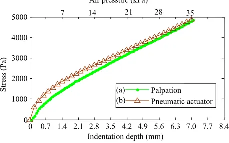
[image:4.612.326.553.182.284.2]Fig. 9 shows (a) the interaction stress at the interaction center caused by the palpation indentation on the soft tissue without any hard inclusions embeded and (b) the stress change caused by the actuator. Air pressure 35 kPa applied to the pneumatic actuator could simulate 7.0 mm palpation indentation. The RMS error is 221.5 Pa (4.4%). Fig.10 shows (a) the interaction stress change at the interaction center caused by the palpation indentation with a hard inclusion embeded and (b) the stress change caused by the actuator. Air pressure 58 kPa applied to the pneumatic actuator could simulate 7.0 mm palpation indentation. The RMS error is 286.3 Pa (3.6%).
[image:4.612.325.561.313.403.2]Figure 6. The stress distribution for palpaiton on a soft tissue without any hard nodule embedded.
Figure 7. The stress distribution for palpaiton on a soft tissue with a hard nodule embedded.
Figure 8. The stress distribution for the interaction between the fingertip and the pneumatic actuator.
Figure 9. The stress at the fingertip center caused by the palpation indentation (0-7 mm indentation depth) on the soft tissue without any hard inclusions embeded, shown in (a), and the stress caused by the actuator (0-35
kPa air pressure), (b).
0 0.7 1.4 2.1 2.8 3.5 4.2 4.9 5.6 6.3 7.0 7.7 8.4 0
1000 2000 3000 4000 5000
St
re
ss (P
a)
Indentation depth (mm) Palpation Pneumatic actuator
35
7 14 21 28
Air pressure (kPa)
[image:4.612.319.548.440.583.2]Figure 10. The stress at the fingertip center caused by the palpation indentation (0-7 mm indentation depth) on the soft tissue with a hard inclusion
embeded, shown in (a) , and the stress caused by the actuator (0-58 kPa air pressure), (b).
C. User study
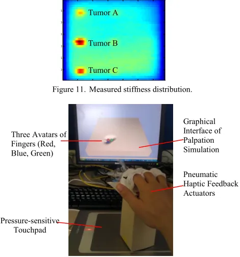
[image:5.612.46.285.70.204.2]To prove the feasibility of the developed actuator, a user study on multi-fingered palpation haptics was conducted. The stiffness distribution map is shown in Fig. 13. A pressure-sensitive touchpad is used as a position and normal force input device. Both the graphical feedback of tissue deformation through computer graphics and mechanical feedback via the pneumatic haptic feedback actuators were provided. Nine subjects were involved in this study. None of them had any palpation experience. All participants could feel the simulated stiffness differences. The measured stiffness distribution came from a silicone phantom soft tissue embedded with artificial tumours A, B, C (see Fig. 12), which were plastic cubes with thickness of 4 mm, 12 mm and 8 mm. The detection rates of simulated tumour A, B, C were 66.7%, 100%, and 88.9%, respectively. There was a positive correlation between the detection rates and nodule sizes.
Figure 11. Measured stiffness distribution.
Figure 12. Experimental setup for evaluation test.
V. DISCUSSION
Some hysteresis can be observed between inflation and deflation, Fig. 3. Further analysis is needed. There are some differences on mid- to high-range the deflections between the different finger actuators, which might be overcome by a standardized fabrication process. During the evaluation tests, it is found that a single palpation indentation behavior could not continue for a long time because there is a reaction time accumulation for the air pressure control. If the desired air pressure values are continuously received, the pressure regulators need to respond all the commands sequentially. Thus, the respond time of the regulators is accumulated. Further study is needed to reduce the reaction time accumulation of the actuators. Preliminary results demonstrate relatively good tumor detection rates, showing direct correlation between tumor size and detection rate. In the future, studies should be carried out involving medical subjects with palpation experience. A further comparison study between a single-point force feedback palpation and the proposed multi-fingered palpation would be helpful to demonstrate the advantages of the proposed method.
VI. CONCLUSIONS
This paper presents a multi-fingered pneumatic actuator system that allows a user to carry out palpation of soft tissue experiencing haptic sensations at multiple fingers. The system changes the stiffness of air balloons (attached to fingertips) to simulate soft tissue stiffness and recreates the deformation of fingers, as experienced during palpation. This principle is proved by examining the deflection response of the actuators, analyzing the contact stress and finger tip deformation using finite element analysis, and evaluating the performance of tumor identification in a user study. The results proved that the stress changing of fingertips during palpation can be recreated by using our pneumatic multi-fingered haptic feedback method. The proposed pneumatic haptic feedback actuator provides a solution for multi-fingered palpation haptics. With real-time tactile sensing data, the application of this actuator can be extended from simulated haptics to intra-operative palpation haptics.
ACKNOWLEDGMENT
We thank both the engineering and medical community for their helpful discussions and comments. The work described in this paper is partially funded by the Seventh Framework Programme of the European Commission under grant agreement 287728 in the framework of EU project STIFF-FLOP, as well as by the National Institute for Health Research (NIHR) Biomedical Research Centre based at Guy's and St Thomas' NHS Foundation Trust and King's College London. The views expressed are those of the authors and not necessarily those of the NHS, the NIHR or the Department of Health.
REFERENCES
20 40 60 80 100 120 5
10 15 20 25
30 Tumor C
Tumor B Tumor A
Indentation depth (mm)
St
re
ss (P
a)
0 0.7 1.4 2.1 2.8 3.5 4.2 4.9 5.6 6.3 7.0 7.7 8.4 0
2000 4000 6000 8000
Pneumatic actuator Palpation
58 11.6 23.2 34.8 46.4
Air pressure (kPa)
(a) (b)
Pressure-sensitive Touchpad
Pneumatic Haptic Feedback Actuators Three Avatars of
Fingers (Red, Blue, Green)
[image:5.612.51.286.461.713.2]fingered palpation, Proceeding of IEEE International conference on System, Man and Cybernetics, 2013, 4184-4189 [1] M. Mahvash, J. Gwilliam, R. Agarwal, B. Vagvolgyi, L.-M. Su, D. D.
Yuh, and A. M. Okamura, “Force-Feedback Surgical Teleoperator:
Controller Design and Palpation Experiments,” 2008 Symposium on Haptic Interfaces for Virtual Environment and Teleoperator Systems, no. Figure 1, pp. 465–471, Mar. 2008.
[2] A. P. Miller, W. J. Peine, J. S. Son, and M. D. Z. T. Hammoud, “Tactile
imaging system for localizing Lung nodules during video assisted
thoracoscopic surgery,” Proceedings 2007 IEEE International
Conference on Robotics and Automation, pp. 2996–3001, Apr. 2007.
[3] T. Yamamoto and N. Abolhassani, “Augmented reality and haptic
interfaces for robot‐ assisted surgery,” The International Journal of Medical Robotics and Computer Assisted Surgery, vol. 8, no. November 2011, pp. 45–56, 2012.
[4] C. King, M. O. Culjat, M. L. Franco, J. W. Bisley, G. P. Carman, E. P.
Dutson, and W. S. Grundfest, “A multielement tactile feedback system
for robot-assisted minimally invasive surgery,” Haptics, IEEE Transactions on, vol. 2, no. 1, pp. 52–56, 2009.
[5] S.-Y. Kim, K.-U. Kyung, J. Park, and D.-S. Kwon, “Real-time area-based haptic rendering and the augmented tactile display device for a
palpation simulator,” Advanced Robotics, vol. 21, no. 9, pp. 961–981,
Sep. 2007.
[6] M. Culjat, C.-H. King, M. Franco, J. Bisley, W. Grundfest, and E.
Dutson, “Pneumatic balloon actuators for tactile feedback in robotic
surgery,” Industrial Robot: An International Journal, vol. 35, no. 5, pp.
449–455, 2008.
[7] W. Schiff and E. Foulke, Tactual perception: a source book. 1982.
[8] L. R. Gavrilov, E. M. Tsirulnikov, and I. A. Davies, “Application of
focused ultrasound for the stimulation of neural structures,” Ultrasound in Medicine and Biology, vol. 22, no. 2, pp. 179–192, 1996.
[9] K.-U. K. K.-U. Kyung, M. A. M. Ahn, D.-S. K. D.-S. Kwon, and M. A.
Srinivasan, “Perceptual and biomechanical frequency response of human
skin: implication for design of tactile displays,” in First Joint
Eurohaptics Conference and Symposium on Haptic Interfaces for Virtual Environment and Teleoperator Systems World Haptics Conference, 2005, pp. 96–101.
[10] V. Chouvardas, a Miliou, and M. Hatalis, “Tactile displays: Overview
and recent advances,” Displays, vol. 29, no. 3, pp. 185–194, Jul. 2008.
[11] W. McMahan and J. Gewirtz, “Tool contact acceleration feedback for
telerobotic surgery,” IEEE Transactions on Haptics, vol. 4, no. 3, pp.
1939–1412, 2011.
[12] I. Tactus Technology, “Tactus Technology,” 2012. [Online]. Available:
http://www.tactustechnology.com/index.html.
[13] T. Nara, M. Takasaki, T. Maeda, T. Higuchi, S. Ando, and S. Tachi,
“Surface acoustic wave tactile display,” IEEE Computer Graphics and
Applications, vol. 21, no. 6, pp. 56–63, 2001.
[14] W. Khaled, S. Reichling, O. T. Bruhns, H. Boese, M. Baumann, G. Monkman, S. Egersdoerfer, D. Klein, A. Tunayar, H. Freimuth, A.
Lorenz, A. Pessavento, and H. Ermert, “Palpation imaging using a haptic
system for virtual reality applications in medicine,” Studies in Health Technology and Informatics, vol. 98, pp. 147–153, Jan. 2004. [15] J. Gregory, Y. Shen, and N. Xi, “Stimulation Current Control for Load
-Aware Electrotactile Haptic Rendering: Modeling and Simulation,”
International Conference on Robotics and Automation (ICRA), 2011. [16] Y. Kim, I. Oakley, and J. Ryul, “Design and Psychophysical Evaluation
of Pneumatic Tactile Display,” pp. 1933–1938, 2006.
[17] N. A. Langrana, G. Burdea, K. Lange, D. Gomez, and S. Deshpande,
“Dynamic force feedback in a virtual knee palpation.,” Artificial
Intelligence in Medicine, vol. 6, no. 4, pp. 321–333, 1994.
[18] M. Dinsmore, N. Langrana, G. Burdea, and J. Ladeji, “Virtual Reality
Training Simulation for Palpation of Subsurface Tumors,” in IEEE Virtual Reality Annual International Symposium, 1997, pp. 54–60. [19] V. Daniulaitis and M. O. Alhalabi, “Medical Palpation of Deformable
Tissue using Physics-Based Model for Haptic Interface RObot
( HIRO ),” in Information Systems, 2004, pp. 3907–3911.
[20] H. Kawasaki, J. Takai, Y. Tanaka, C. Mrad, and T. Mouri, “Control of
multi-fingered haptic interface opposite to human hand,” in Proceedings 2003 IEEERSJ International Conference on Intelligent Robots and Systems IROS 2003, 2003, vol. 3, no. October, pp. 2707–2712. [21] T. Endo, H. Kawasaki, T. Mouri, Y. Doi, T. Yoshida, Y. Ishigure, H.
Shimomura, M. Matsumura, and K. Koketsu, “Five-fingered haptic
interface robot: HIRO III,” World Haptics 2009 Third Joint EuroHaptics
conference and Symposium on Haptic Interfaces for Virtual
Environment and Teleoperator Systems, vol. 4, no. 1, pp. 458–463, 2009. [22] C. D. Clemente, Anatomy: a Regional Atlas of the Human Body (Second
Edition). Urban and Achwarzengerg, Baltimore, Munich, 1981. [23] J. Z. Wu, K. Krajnak, D. E. Welcome, and R. G. Dong, “Analysis of the
dynamic strains in a fingertip exposed to vibrations: Correlation to the
mechanical stimuli on mechanoreceptors.,” Journal of Biomechanics,
vol. 39, no. 13, pp. 2445–2456, 2006.
[24] D. Klemm, “Fingertip anatomy.” [Online]. Available:
http://www8.georgetown.edu/dml/facs/graphics/POP-UPS/pop-up-fingernail.html.
[25] H. Yamada, Strength of Biological Materials. Baltimore, MD: Willians and Wilkins Co., 1970.
[26] E. M. Arruda and M. C. Boyce, “A three-dimensional constitutive model
for the large stretch behavior of rubber elastic materials,” Journal of the
Mechanics and Physics of Solids, vol. 41, no. 2, pp. 389–412, 1993. [27] K. Sangpradit, H. Liu, P. Dasgupta, K. Althoefer, and L. D. Seneviratne,
“Finite-element modeling of soft tissue rolling indentation.,” IEEE
Transactions on Biomedical Engineering, vol. 58, no. 12, pp. 3319–3327, Dec. 2011.