1
Deliverable:
D4.1 Definition of specifications for robotic prototype
Work Package:
WP4 Smart machinery for strip-cropping systems
Responsible:
Centre for Automation and Robotics (CAR)
2
Version control
Version Description Date Approval
D4.1 Robotic
Prototype v1.0 Specifications of Robotic Prototype for strip-cropping systems
January 24th, 2019 Juan Jesús Roldán
D4.1 Robotic
Prototype v1.1 Fixing comments after first internal review
February 15th, 2019 Jaime del Cerro Antonio Barrientos
D4.1 Robotic
Prototype v2.0 Collect revision suggestions of UPM project partners
3
Table of contents
1. Introduction ……….. 5
2. Methodology ……… 6
3. Requirements ………... 8
3.1. Global requirements ……… 8
3.2. Cart requirements ………. 8
3.3. Robot requirements ………. 9
3.4. Sensor requirements ……….. 9
3.5. Actuation requirements ……….. 9
3.6. Processing and decision-making requirements ……… 9
3.7. Communication and interface requirements ……… 10
3.8. Validation requirements ……… 10
4. Design ………. 11
4
List of figures
Figure 1: Functional design of the robotic prototype ………... 11
Figure 2: Schematic design of the cart ……….. 11
Figure 3: Morphology of manipulator robot ……….…. 13
Figure 4: Simulation of the robot in multiple configurations ………. 13
e
List of tables
Table 1: Robot features ……….……… 125
1.
Introduction
The SUREVEG project proposes the development and application of new organic cropping systems using strip-cropping and fertility strategies to improve resilience, system sustainability, local nutrient recycling and soil carbon storage. The project has three main goals: 1) Designing and testing strip-cropping systems in vegetable producing countries at different geographical locations in Europe, 2) Developing and testing soil-improvers and fertilizers based on pre-treated organic plant residues, and 3) Developing and testing smart technologies for management of strip-cropping systems.
The WP4 of the SUREVEG project is focused on the third goal: Smart machinery for strip-cropping systems. This WP aims at developing a robotic tool for the automation of field operations in strip-cropping systems, including the adequate sensors to collect valuable data and actuators to apply precise fertilization. Specifically, this WP comprises four goals: 1) Designing a multi-purpose robotic tool, 2) Developing sensing systems and algorithms, 3) Developing an actuation system, and 4) Implementing motion planning strategies.
This document, entitled D4.1 Definition of specifications for robotic prototype, corresponds to the first deliverable of WP4 in the SUREVEG project. It describes the technical specifications for the prototype, in order to automate the management of strip-cropping systems. Therefore, this document defines the work to be performed in WP4 and impacts the next deliverable, i.e., D4.2 Integrated Prototype.
6
2.
Methodology
As previously mentioned, WP4 is focused on developing a robotic prototype for the management of strip-cropping systems. The rest of the WPs in the project are involved in the development of these agronomic systems: WP1 collaborates with stakeholders to identify their needs and defines the strategy for the implementation of strip-cropping systems, WP2 deals with the selection of main and cover crops used by these systems according to the different geographic areas, and WP3 conducts the farm trials, planning the fertility strategies and evaluating the performance results. Therefore, it can be said that the activities of WP4 highly depend on the needs of the other WPs in the SUREVEG project. This fact is reflected in the methodology followed in the definition of the prototype, which is as follows:
1) Analysis of application 2) Definition of requirements
1) Global requirements 2) Cart requirements 3) Robot requirements 4) Sensor requirements 5) Actuation requirements
6) Processing and decision-making requirements 7) Interface and communication requirements 8) Validation requirements
3) Design of prototype
The methodology arises from the application (the management of strip-cropping systems) by studying the requirements (sensing and actuation needs) and restrictions (features of the scenario). However, since the final goal of the WP4 is to develop a proof of concept and this WP is executed simultaneously with the others, the prototype has to be designed to work in a specific scenario under certain conditions. Therefore, the first step is to analyze the application to determine the objectives, requirements and limitations.
The requirements of the system are derived from the application. They are listed with an identification number and each defined with a sentence. This sentence has to describe unequivocally a condition that the system should meet. Whenever possible, every requirement should define a unique condition. For instance, if the system has to meet two closely related conditions, they are proposed in two separate requirements.
7
8
3. Requirements
3.1. Global requirements
R101: The system shall work in strip-cropping systems.
R102: The system shall operate on selected winter (for example, leeks, beans and cabbage) and summer crops (i.e., tomato, beans and pumpkin).
R103: The system shall move along crop rows with widths in the range of 1-1.4 meters, heights between 0.2 and 0.6 meters and lengths between 10 and 100 meters.
R104: The system shall operate without damaging the plants.
R105: The system shall collect information of the spatial and time heterogeneities in the crops.
R106: The system shall recognize crops and weeds.
R107: The system shall determine the type, location and health of the plants.
R108: The system shall early detect plant problems.
R109: The system shall provide information about the health of the crops, such as some symptoms of diseases: e.g., water stress and abnormal colors.
R110: The system shall apply liquid treatments to the crops.
R111: The treatments will be applied to the ground around the target plant.
R112: The system shall consist of a wheeled cart, a manipulator robot and the required components for sensing and actuation tasks.
R113: The system shall have a protection of IP54 against solid particles and liquids.
3.2. Cart requirements
R201: The cart shall consist of a structure of bars with four wheels, similar to the gantry systems used in controlled traffic farming or pivot irrigation systems.
R202: The cart shall have an axle track in the range of 1.2 to 1.5 meters to move along the rows without damaging the crops.
R203: The cart shall have clear height of 1 to 1.4 meters over the ground to hold the robot, sensors and actuators that must work over the plants.
R204: The cart shall have a wheelbase of at least 1 meter to be able to collect data of the plants in a circle with a diameter of 1 meter.
R205: The cart shall carry a payload of at least 120 kilograms, which includes the estimated weights of the manipulator (25 kg), the components required to power and control it (25 kg), the tank for the liquid treatments (60 kg), the actuators required to apply them (5 kg) and the sensors and cameras (5 kg).
9
3.3. Robot requirements
R301: The robot shall hang down from the structure of the cart.
R302: The robot shall reach the plants to acquire data and apply treatments.
R303: The robot shall be able to place its tool within a circle with a diameter of 1 meter at a height of 0.2 meters over the ground.
R304: The robot shall have a reach (i.e., a distance between the base and the tool) of at least 600 millimeters.
R305: The robot shall have a precision of at least 10 millimeters in the positioning of its tool.
R306: The robot shall have a maximum weight of 50 kilograms, including not only the electromechanical components, but also the power and control equipment.
R307: The robot shall have a load capacity of 1.5 kilograms in operation positions to carry out sensing and actuation elements.
R308: The robot shall be able to reach most of the points inside the workspace defined by previous requirements with different orientations of the tool.
R309: The robot shall be protected from dust and water jets.
3.4. Sensor requirements
R401: As a proof of concept, the prototype shall focus on only one sensing technology.
R402: The prototype shall integrate a camera to take multispectral images.
R403: The prototype shall be able to take pictures of the crops in a circle with a diameter of 1 meter and below the cart with enough resolution to distinguish separate plants.
R404: The prototype may integrate other complementary sensing technologies, such as RGB cameras, LIDARs, spectroscopes and stereo cameras.
3.5. Actuation requirements
R501: As a proof of concept, the prototype shall focus on only one plant treatment.
R502: The prototype shall be able to spray a liquid treatment.
R503: The prototype shall actuate on the ground around the plants.
3.6. Processing and decision-making requirements
R601: The operator shall be able to supervise the operations of the system remotely.
R602: The operator shall be able to start/stop the complete system at any moment.
R603: The operator shall dictate the targets where specific measurements and treatments are required to the robot.
10
R605: The sensing system shall work continuously and autonomously during the operation.
R606: The operator shall be able to start/stop the actuation system.
R607: The system shall identify each plant and provide an index regarding its state, as well as recommend a treatment.
3.7. Communication and interface requirements
R701: The interface shall show the relative location of the cart in the strip cropping field: e.g., provide the number of the crop row and the distance from the beginning.
R702: The interface shall show real-time relative position of the robot to the cart, including both the states of its joints and the position and orientation of its tool.
R703: The interface shall show all the camera images and sensors measurements.
R704: The interface shall allow the operator to send pose goals to the tool of the robot.
R705: The interface shall allow the operator to activate/deactivate the treatment spray.
R706: The interface shall allow the operator to stop the system in case of emergency.
R707: All the systems shall be communicating using a Wi-Fi network.
R708: The software shall be developed by using common assets in the world of robot planning and control.
R709: The software shall be developed in modules, so it can be expanded to add new functions.
3.8. Validation requirements
R801: The system shall be validated through both component and global tests.
R802: The tests shall take place in a strip-cropping field in Madrid (Spain).
R803: The requirements of the robot shall be validated independently in laboratory experiments and integrated in the system in field experiments.
R804: The robot shall be validated by dictating 20 randomly generated pose goals within its workspace and measuring its precision (defined as the distance between commanded and reached poses) (R303, R304 and R305).
R805: The sensing system shall be validated in field experiments.
R806: The requirements of the sensing system (R402, R403 and R404) shall be validated by mapping a complete crop row as defined by R102 and R103
R807: The actuation system shall be validated in field experiments.
11
4. Design
[image:11.595.182.419.218.447.2]In order to meet the requirements (R101-R113), the system will be made up of a cart, a manipulator robot, a tank with spraying system, sensors and cameras. A functional design of the system is shown in Figure 1, where the cart is shown in gray, the manipulator robot and control box in blue, the treatment tank and sprayer in purple, the sensors and cameras in red, and the control elements in cyan. It must be highlighted that this is a functional design, so the locations, shapes and sizes of the different elements can vary in the prototype.
Figure 1: Functional design of the robotic prototype
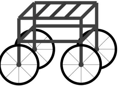
The cart will be made up of a metal frame (bars) and four wheels (R201-R204). The frame will support the different elements (R205) and will not rely on an autonomous traction system (R206). A simple representation of this cart can be seen in Figure 2.
[image:11.595.202.401.552.696.2]12
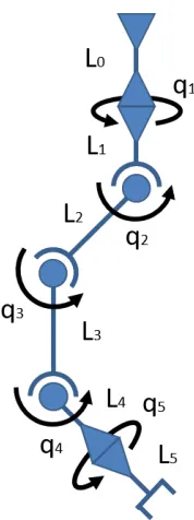
As shown in Figure 1, the robot will hang down from the structure (R301) and will be able to reach the ground to acquire data and apply treatments (R302). Table 1 collects the main robot features obtained from the requirements. A minimum of 5 degrees of freedom (DoF) has been considered to meet the requirements related to the range and mobility of the robot. In addition, a minimum protection against solid particles and liquids of IP54 is chosen, which means the robot is effective against both dust (ingress of dust is not entirely prevented, but the quantity remains low enough to not interfere with the satisfactory operation of the equipment) and water splashing (water splashing against the enclosure from any direction shall have no harmful effect). Finally, the robot must be able to perform trajectories from point to point, as well as to follow straight lines and splines.
Feature Value Requirement
Reach 600 mm R304
Load capacity 1.5 kg R307
Degrees of freedom 5 R303, R308
Power Electrical -
IP IP54 R113, R309
[image:12.595.86.514.239.339.2]Trajectories Point to point, lines, splines. R303, R308 Table 1: Robot features
Three options were considered for the development of the robot with these features: A. Search and buy a commercial robot.
B. Develop the robot with commercial modules. C. Design and build the robot from scratch.
An analysis revealed that each option has some advantages and drawbacks. On the one hand, A implies less effort in development and integration, but may not meet all the requirements defined by the application. On the other hand, C maximizes the adaptation of the robot to the application, but may imply an unaffordable effort considering the available time and budget. Finally, B can be considered a compromise between A and C, allowing to meet the requirements with a moderate effort. Therefore, the option B was chosen.
13
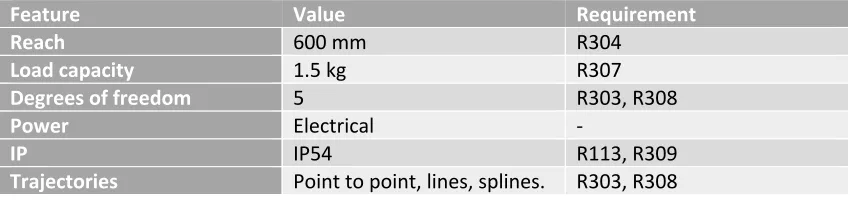
Figure 3: Morphology of the manipulator robot
The following lengths have been chosen for the different modules: L0=0, L1=0, L2=350mm, L3=270mm, L4=170mm and L5=0. According to the preliminary design (Figure 4) and the specifications of the manufacturer (Igus), the robot will have a reach of 790 millimeters (R304) and a precision of 1 millimeter (R305). Additionally, it will weight around 20 kg (R306), including the electromechanical components and excluding the control and power elements, and have a load capacity of around 2.5 kg (R307).
Figure 4: Simulation of the robot in multiple configurations
Regarding the sensors, a multispectral camera will be used to obtain multispectral images and compute NDVI indices of plants (R401-R402). This camera can be installed in the tool of the manipulator or in the frame of the cart, in order to take pictures of the target plants from the desired perspectives (R403). Additionally, a laser scanner will be integrated in the cart to obtain 3D models of the soil and plants, which will ease the motion planning of the manipulator robot and the application of treatments in the adequate locations (R404).
[image:13.595.87.515.452.593.2]14
the manipulator robot will reach the position and orientation where the sprayer should apply the treatment (R503).
An operator interface will be developed to monitor and control the system work (R601). This interface will allow the operator to start/stop the system (R602), send pose goals to the robot (R603) and activate/deactivate the actuator (R606). The interface will provide the operator with information about the state of the cart (R701) and robot (R702). Additionally, it will show the 3D model of the crop row and the multispectral images of the plants (R703).