University of Southern Queensland
Faculty of Engineering & Surveying
Field Deployable Shower Unit
By Dual Membrane Filtration
A dissertation submitted by
Eugene Tinning
In fulfilment of the requirements of
Courses ENG4111 and ENG4112 Research Project
towards the degree of
Abstract
Through the research and investigation of filtration systems both micro-filtration and ultra-filtration as well as reverse osmosis technology and techniques a conceptual a conceptual Field Deployable Shower Unit (FDSU) will be designed for the Department of Defence and for the potential use by humanitarian agencies and other Emergency Services during deployment to the field and whilst on disaster and humanitarian relief throughout the world. The FDSU will be designed to operate using supplied water or brackish water, dam water, bore or river water up to a TDS of 20,000 mg/L. The FDSU will also have the engineered redundancy to desalinate and process salt water on
occasion as required.
The system will be designed based on current filtration and reverse osmosis technology as well as being based on current water purification equipment employed by the
Department of Defence, whether the equipment is in general use or whether it is used as a subassembly in another system. The system will also be designed with the capability of being piggy backed directly on to the current water purification unit (WPU)
employed by the Department of Defence. The DFSU design comprises of four main sections. These sections include the input or pre-filtration section, the micro-filtration section, the reverse osmosis membrane treatment section and the recycled/reclaimed water section. The water that is supplied from the WPU will bypass the input/pre-filtration, micro-filtration and reverse osmosis membrane sections.
The input / pre-filtration section pumps the water from the supplied water source whether it is in tanks or from a dam etc through a strainer to remove residual
back flushable filter that is 400 microns in size to remove smaller contaminants. It is pumped to a micro-filtration feed tank where it is dosed with a chlorine solution en-route to disinfect the water prior to entering the micro-filtration section.
The micro-filtration section receives the chlorine dosed water via a pump which raises the pressure of the water to between one and a half and two bar in order to force the water through the micro-filtration section. The micro-filtration section has the capability to be reverse flushed for cleaning, de-scaling and de-fouling of the filter during
operation. The water is then treated with a sodium bisulphate solution to neutralise the chlorine as the reverse osmosis membranes are sensitive to chlorine.
The reverse osmosis membrane section has the water fed to it via a high pressure pump which raises the water pressure to 45 bar based on a brackish water with a TDS of 20,00 mg/L in order to overcome the osmotic pressure and force the water through the reverse osmosis membrane. Based on the brackish water supply with a 60% permeate return for use in the shower, the system would require a constant supply of water at approximately 3,300 litres/hour once it has been run up and the recycled/reclaimed water is being processed and returned for use in the FDSU.
The recycled/reclaimed water section comprises of a back flushable filter with a pump that pumps the water from the shower sump through the back flushable filter through to the micro-filtration feed tank where it is dosed with a chlorine solution en-route to disinfect the water prior to entering the micro-filtration section.
the use in the Field Deployable Shower Unit. The construction and testing of a prototype and ultimately the project for the construction of the required amount of Field
Deployable Shower Units will be solely reliant on the decision that the Department of Defence make in regards to whether the FDSU concept meets their requirements.
Certification
I certify that the ideas, designs and experimental work, results, analyses and conclusions set out in this dissertation are entirely my own effort, except where otherwise indicated and acknowledged.
I further certify that the work is original and has not been previously submitted for assessment in any other course or institution, except where specifically stated.
Eugene Tinning
Student Number: 0019521802
____________________________________________ Signature
Acknowledgments
Professor David Ross, Head of Discipline for Mechanical and Mechatronic, Faculty of Engineering and Surveying, University of Southern Queensland, Toowoomba,
Queensland Australia. I would like to thank Professor David Ross for his overall guidance and constructive criticism in all facets of the development and design of the project and the formatting of my project specification, project presentation and project dissertation.
Dr Gibb C. Y. Chan, Technical Director Membrane Systems, Pall Australia, Lane Cove, New South Wales Australia. I would like to thank Dr Gibb Chan for his continual technical guidance and support as well as his practical advice.
Contents
ABSTRACT………..ii DISCLAIMER………..v CERTIFICATION………..vi ACKNOWLEDGMENTS………. vii CONTENTS………... viiLIST OF FIGURES……… xi
GLOSSARY OF TERMS……….xiii
CHAPTER 1………. 1
INTRODUCTION………1
1.1Project Aim……….1
1.2Project Objectives……….. 1
1.3Project Overview………2
CHAPTER 2………. 4
BACKGROUND……….. 4
2.1CURRENT BATH UNIT AND SITUATION………. 4
2.1.1 Current Bath Unit………4
2.1.2 Situation……… 5
CHAPTER 3………. 8
CURRENT TECHNOLOGIES……….. 8
3.1CURRENT DISINFECTION THEORY………. 8
3.1.1 Disinfection Technologies……… 8
3.2CURRENT FILTRATION THEORY………... 10
3.2.1 Pre-filtration………... 10
3.2.2 Micro-filtration………...10
3.2.3 Ultra-filtration………13
3.2.4 Nano-filtration………14
3.3REVERSE OSMOSIS THEORY………... 15
3.3.1 Osmosis………... 15
3.3.2 Reverse Osmosis……….16
3.3.3 Reverse Osmosis Membranes………... 19
3.3.4 Spiral Wound Membranes……… 19
CHAPTER 4………... 24
DUAL MEMBRANE DESIGN REQUIREMENTS……….. 24
4.1 FEEDWATER SOURCES AND COLLECTION………... 24
4.2 WATER STANDARDS……….. 25
4.3 PRODUCTION REQUIREMENTS………. 26
4.4 OPERABILITY………...27
4.5 MAINTENANCE……… 27
4.6 CLEANING REGIME………... 28
4.7 SUB-ASSEMBLES AND COMPONENTS……….. 29
4.8 TRANSPORTATION AND CONTAINMENT………... 29
4.9 SELECTED MICRO-FILTRATION MEMBRANE……….. 30
4.10 SELECTED REVERSE OSMOSIS MEMBRANE……… 31
4.11 PUMPS………33
CHAPTER 5………... 34
PROJECT DESIGN METHODOLOGY……….34
5.1PROJECT RESEARCH………..34
5.2CONCEPTUAL DESIGN OF THE FDSU………34
CHAPTER 6………... 36
FIELD DEPLOYABLE SHOWER UNIT………...36
6.1CONCEPT OF OPERATIONS……….. 36
6.2INPUT SYSTEM AND TREATMENT………. 37
6.2.1 Input Design………37
6.2.2 Input Pump and Strainer……….. 39
6.2.3 Chlorine and Acid Dosing………. 39
6.3MICRO-FILTRATION SYSTEM………. 39
6.3.1 Micro-filter System……….... 40
6.3.2 Micro-filter System Backwash Process……… 41
6.4REVERSE OSMOSIS SYSTEM……… 42
6.4.1 Reverse Osmosis System Design………... 42
6.4.2 Membrane System………. 43
6.5POST REVERSE OSMOSIS TREATMENT………... 44
6.5.1 Post Reverse Osmosis Design………44
6.6 CHEMICAL DOSING AND CLEANING………... 45
6.6.1 Chemical Dosing……….45
6.6.2 Chemical Cleaning………. 46
CHAPTER 7………...47
DESIGN MODIFICATIONS………47
CHAPTER 8………... 49
RESOURCE ANALYSIS……….. 49
8.1MICRO-FILTRATION MEMBRANES (Pall Microza)………. 49
8.2REVERSE OSMOSIS MEMBRANE FILTERS (Pall)………50
8.3VALVES AND PNEUMATIC ACTUATORS……….. 52
8.4PUMPS………..53
8.5PRESSURE RELIEF AND REDUCING VALVES………. 54
8.6POWER REQUIREMENTS………...55
8.7PIPING………. 58
8.8PROGRAMMABLE LOGIC CONTROLLER……… 60
8.9INSTRUMENTATION & SENSORS...……….61
8.9.1 Ph Sensor and Instrument……….62
8.9.2 Pressure Sensors……….65
8.9.3 Differential Pressure Sensors………66
8.9.4 Flow Meters……… 68
8.10 CHEMICAL DOSING SYSTEM……….69
8.11 HOSES……… 71
8.12 CONTAINERS………... 72
CHAPTER 9………... 74
CONSEQUENTIAL EFFECTS………74
9.1OUTLINE OF EFFECTS..………..74
9.2ENVIRONMENTAL EFFECTS……… 75
9.3SAFETY EFFECTS……….75
CHAPTER 10 77 CONCLUSION………...77
10.1 ACHIEVEMNETS OF DESIGN CONCEPT..………... 77
10.2 FURTHER WORK……… 78
10.2.1 Waste Water Treatment………78
10.2.2 Water Heating……… 79
REFERENCES……….. 80
APPENDIX A………. 84
Project Specification………..84
APPENDIX B………. 86
QSTAG Potable Water Standard………..86
APPENDIX C………. 87
APPENDIX D………. 89
Micro-filter System Component Description………..89
APPENDIX E………. 92
Reverse Osmosis System Component Description………..92
APPENDIX F………. 96
Data Summary for 16 KVA Generator………..96
APPENDIX G……….97
Specification Sheet for PH8EFP pH/ORP Sensor...………..97
APPENDIX H……….98
Specification Sheet for PH402G pH/ORP Meter…..………98
APPENDIX I……….. 99
List of Figures
Figure 3.1 Separation Chart for Micro-filtration Figure 3.2 Micro-filtration Assembly
Figure 3.3a Micro-filtration Crossflow Figure 3.3b Feedflow Process
Figure 3.4 Molecular Structure of Ultrafiltration Figure 3.5 Osmosis
Figure 3.6 Reverse Osmosis Separation Chart Figure 3.7 Reverse Osmosis
Figure 3.8 A Spiral Wound Membrane Figure 3.9a Disc Tube Assembly Figure 3.9b Disc Tube Component
Figure 4.1a Micro-filter Assembly Side View Figure 4.1b Front View of Micro-filter Assembly Figure 4.2 - Crosscut View of Disc Tube Assembly Figure 6.1 – DFSU General Concept of Operations Figure 6.2 Input Design
Figure 6.3 Micro-filter System Figure 6.4 Reverse Osmosis System Figure 6.5 Post Reverse Osmosis System Figure 8.1 Pall Microza Micro-filter Assembly Figure 8.2 Pall Disc Tube Module
Figure 8.3 Crane Check and Shut Off Valves Figure 8.4 Pneumatic Actuators
Figure 8.6(b) Mack Pressure Relief Valve Figure 8.7 The APD016 16kVA Generator Figure 8.8 316 Stainless Steel Piping
Figure 8.9 Allen-Bradley Programmable Logic Controller
Figure 8.10 PH8EFP pH Sensor
Figure 8.11 PH402G pH Meter
Figure 8.12 EJA Series Gauge Pressure Transmitter Figure 8.13 EJA110 Differential Pressure Transmitter Figure 8.14 Various AXF Series Flowmeters
Glossary of Terms
Absorption
(gen.) The taking in, incorporation or reception of gases, liquids, light or heat. (phys/chem) Penetration of one substance into the inner structure of another (cf. adsorption, in which one substance is attracted and held on the surface of another). Occurs between a gas or vapour and a liquid.
(pharm.) The process of movement of a drug from the site of application into the extracellular compartment of the body.
Adsorption
Retention of gas, liquid, solid or a dissolved substance on a surface due to positive interaction (attraction) between the surface and the molecules of the adsorbed material. The interactive forces can be electrostatic (coulombic) or nonelectrostatic (dipole-dipole and hydrophobic). Adsorption to a membrane or filter device can occur in a specific manner (affinity) or non-specifically.
Air Scrubbing (AS)
AS is another way to clean the membrane hydraulically. During
AS, air is injected into the bottom of the filter module. The combined water-air flow creates strong turbulent and shear forces to dislodge dirt deposited on the membrane surface. Forward flush or reverse flow are used to remove the solids dislodged during air scrubbing. Sometimes air scrubbing is combined with reverse filtration, termed as simultaneous air scrubbing and reverse filtration (SASRF), as the means of hydraulic cleaning.
Antigen
A foreign substance (usually proteinaceous or high molecular weight polysaccharide) which induces the formation of antibodies. Examples are bacteria, viruses,
endo/exotoxins, pollen and vaccines.
Backwash
Reversing the flow of liquid through a filter in order to remove trapped solids.
Bacteria (Bacterium)
Free living simple celled, microscopic organisms having a cell wall and characteristic shape (e.g., round, rod-like, spiral or filamentous); lack a defined nucleus.
Bar
A unit of pressure. One bar = 14.5 psi.
Biomass
The total weight of living matter present in a specific area.
Blinding
The reduction or cut off of flow due to particles filling the pores of a filter.
Cartridge or Filter Cartridge
Clarification
To clear a liquid by filtration, by the addition of agents to precipitate solids, centrifugation, or by other means.
Coagulation
The destabilization and initial aggregation of finely divided suspended solids by the addition of a polyelectrolyte or a biological process.
Concentrate
Sample not filtered by a membrane. See Retentate.
Crossflow
Flow of solution parallel to the upstream surface of the membrane (see also Tangential Flow Filtration). This contrasts with direct flow seen in traditional filters, in which the liquid flows perpendicular to the surface of the filter.
Crossflow (Tangential Flow) Filtration
A filtration system in which the feed stream flows across the filter media and exits as a retentate stream. The retentate stream is recycled to merge into the feed stream, while a portion of it passes through the filter media, resulting in concentration of the feed stream (referred to as retentate or concentrate). Tangential flow is by far the most effective way to perform ultrafiltration for samples greater than 150 mL. The Ultrasette™ tangential flow device can be used to purify and desalt protein solutions for most lab applications. TFF systems can easily be scaled up to larger scale process applications.
Cryptosporidium
A protozoan parasite that can live in the intestines of humans and animals.
Dead End (Conventional) Filtration
Feed stream flows in one direction only, perpendicular to and through the filter medium to emerge as product of filtrate. Sometimes referred to as "single pass" filtration. Syringe filters, disc membranes, capsules, and cartridges are used in this process.
Depth Filtration
Depth filtration is the process that traps contaminants both within the matrix and on the surface of the filter media. Depth filters are composed of random mats of metallic, polymeric, or inorganic materials. These filters rely on the density and thickness of the mats to trap particles, and generally retain large quantities of contaminants within the matrices. Media migration, which is the shifting of the filter medium under stress, and particulate unloading are potential problems.
Differential Pressure
Direct Flow Filtration
Filtration in which liquid flow is directly through the filter medium.
Distillation
The vaporization and subsequent condensation of a liquid. It is used to purify liquids and to separate liquid mixtures.
Feed
The unfiltered liquid. Often used in the phrase "feed stream", the flow of liquid into the filtration system.
Filter (Noun)
An apparatus which performs filtration.
Filter (Verb)
To pass a fluid through a porous medium in order to remove solid particles.
Filter Element
A filter element is a single component, which includes filter media and any supporting materials and other hardware, which must be installed or replaced as a single unit. A common example is a filter cartridge.
Filtrate (Permeate)
Portion of the solution that has passed through the membrane.
Filtration
Process by which particles are removed from a fluid by passing the fluid through a permeable material. See Crossflow (Tangential Flow) Filtration, Dead End
Flow Decay
Decrease in flow rate as a result of filter plugging or clogging.
Flux
The amount of solution that passes through a unit of membrane area in a given amount of time. For instance, a filter might have a flux of 1 litre per minute per square
centimetre. Flux decreases as the membrane fouls.
Fouling
Contamination (plugging) of the membrane, decreasing flux. Often requires chemical cleaning of the membrane.
Giardia Lamblia
A protozoan parasite responsible for giardiasis.
Head
An end closure for the filter Bowl, which contains one or more connections through which the fluid to be filtered passes. The component to which a filter cartridge is sealed.
Housing
The device that encloses a filter element and directs the flow of fluid through it. See Bowl.
Hypochlorite
A weak, unstable salt of hypochlorous acid used in aqueous solutions as a bleach, oxidizer, deodorant and disinfectant.
Integrity Test
A test to ensure that a sterilizing-grade filter is intact and will function as intended. Recommended integrity tests are the Forward Flow Test, Bubble Point test, and the Pressure Hold test. Integrity tests on sterilizing grade filters are correlated with bacterial challenge data.
Medium (Media)
The filter medium is the component of the filter system that actually permits the fluid to pass while retaining contaminants. In a typical drip coffee maker, the medium is the paper filter.
Membrane Recovery
Restoration of the original flux of a membrane after Fouling.
Microfiltration
Microfiltration is the process of removing particles from a liquid or gas by passing it through a porous medium. It generally involves removing particles between the sizes of 10 and 0.02 microns in liquids, and down to 0.003 microns in gases. [See Ultrafiltration, Nanofiltration, Reverse Osmosis (RO)].
Micron (Micrometer)
One one-millionth (0.000001) of one meter, or 0.00003937 inch. Bacteria are typically less than one micron in length. The smallest object visible to the naked eye is
approximately 40 microns across. Human hairs are between 60 and 80 microns in diameter.
Microorganisms
Microscopic organisms such as bacteria, protozoans, yeast, viruses or algae. Typically refers to single-celled organisms that can only be observed under the microscope.
Microporous Membrane
A membrane is a thin, porous film that has flow paths or channels passing through it. The size of these channels is related to the pore size rating of the membrane (0.01 µm to 10 µm). Membranes can be used in the separation or filtration of suspended matter from liquids and gases.
Mil
A unit of measure equal to one thousandth of an inch. 1 mil = 0.001 in. = 0.025 mm. Commonly used to describe the thickness of a membrane or film.
Nanofiltration
Filtration that removes both particles and small dissolved molecules and ions. Finer than Ultrafiltration, not as fine as Reverse Osmosis (RO).
Operating Limits
Minimum and maximum parameters set for validation and processing pressures.
Osmosis
The net flow of solvent through a semi-permeable membrane from a region of high solute concentration to a region of low solute concentration. The flow continues across the membrane until the concentrations in both regions are the same.
Particle
Any discrete unit of material structure; a discernible mass having an observable length, width, thickness, size and shape. By size, the particles range: subatomic or fundamental (protons, neutrons, electrons, etc.); molecular (atoms and molecules, from angstroms to 0.5 µm); colloidal; microscopic (can be resolved by optical microscope, e.g., bacteria); macroscopic (can be resolved by the naked eye).
Particle Size Distribution (PSD)Refers to the number fraction or weight fraction of particles (in a fluid) falling into specified size ranges. For instance:
Size Range # per Litre % by Number (PSD) 5-15 µm 1000 20
15-25 µm 3000 60 25-50 µm 1000 20
Particulate
Relating to or occurring in the form of fine particles.
Permeability
Permeate
Fluid, which passes through a membrane. In ultrafiltration, this term is often used interchangeably with filtrate. To pass through the pores or interstices of something.
pH
The pH value of an aqueous solution is a number describing its acidity or alkalinity. A pH is the negative logarithm (base 10) of the concentration of hydrogen ions
(equivalents per litre). The pH value of a neutral solution is 7. An acidic solution has a pH less than 7, while a basic solution has a pH greater than 7, up to 14.
Polyvinylidene Fluoride (PVDF)
PVDF membranes are naturally hydrophobic but can be modified to a hydrophilic nature. Useful for a wide range of applications: both aqueous and non-aggressive solvent based. It is typically low protein binding and used frequently for sterilizing filtration.
Purified Water, USP
Pharmaceutical water produced by distillation, reverse osmosis or deionization.
Common uses are: a rinse for equipment, vials and ampoules, and as base for cosmetics and oral drugs. It is not used as raw material for parental drugs.
Recovery
Ability of a filter to retain bacteria, DNA or other biomolecules from a solution. Percentage of a chemical that can be recovered after processing.
Rejection
Amount (%) of a molecule that does not pass through a membrane.
Retentate
That which is retained on the upstream side of a membrane filter in a tangential or cross-flow system such as ultrafiltration or reverse osmosis. Often designated as concentrate.
Retention
Ability of a filter to retain particles (total number or those of a specific size) suspended in a gas or liquid. In the case of ultrafiltration, refers to the ability to concentrate
molecules in solution. Expressed as percent of particles or molecules originally present.
Reverse Osmosis (RO)
Forcing a liquid through a nonporous membrane, removing particles, along with dissolved molecules and ions. Reverse Osmosis is the finest form of membrane separation and is used to desalinate water for drinking, and prepare ultrapure water for various industries.
Sanitization, Sanitize
To make clean by removing dirt and other extraneous materials with soap and general disinfectant so as to reduce possibility of growth and spread of pathogenic organisms. A common sanitization agent is 70% ethanol. Bleach is also commonly used.
Sedimentation
Separation
Separation is the process of dividing a fluid stream (either liquid or gas) into separate components. This can include purification (removing something undesirable). This can include separation of two phases (liquid from gas), separation of soluble impurities (known as purification) or solids from a fluid (filtration). The products of a separation can themselves be separated further in many cases.
Serial Filtration
Filtration through two or more filters of decreasing pore size one after the other to increase throughput, filtration efficiency, or to protect the final filter.
Silt Density Index (SDI)
A measure of the fouling tendency of water based on the timed flow of a liquid through a membrane filter at a constant pressure.
Specifications
A detailed, precise description or parameter for identification of limits.
Standard (Normal) Pressure
A pressure of 1 atmosphere (1 bar, 14.70 psi or 760 mm of mercury) to which measurements of quantities dependent on pressure are often referred.
Tangential Flow Filtration (TFF)
Filtration in which liquid flows tangential to (along) the surface of the membrane while pressure is applied that forces liquid through the membrane. The sweeping action of TFF acts to minimize gel layer formation and fouling.
Throughput
The amount of solution which will pass through a filter prior to clogging.
Total Dissolved Solids (TDS)
Total Dissolved Solids are solids in water that can pass through a filter (usually with a pore size of 0.45 micrometers). TDS is a measure of the amount of material dissolved in water. This material can include carbonate, bicarbonate, chloride, sulfate, phosphate, nitrate, calcium, magnesium, sodium, organic ions, and other ions. A certain level of these ions in water is necessary for aquatic life.
Total Suspended Solids (TSS)
The measure of particulate matter suspended in a sample of water or wastewater. After filtering a sample of a known volume, the filter is dried and weighed to determine the residue retained.
Transmembrane Pressure (TMP)
The force which drives liquid flow through a crossflow membrane. The upstream side (the side of the membrane the solution enters by) of a TFF system is under a higher pressure than the downstream side. This pressure difference forces liquid through the membrane.
Turbidity
Ultrafiltration
A low-pressure membrane filtration process that separates solutes in the 20 - 1000 angstrom (up to 0.1 micron) size range.
Upstream Side (of filter)
The feed side of the filter.
Virus
Simple life forms that require a host cell in order to reproduce. Consists of a small number of genes (DNA or RNA) encased in a coat of protein. Viral genes enter a host cell and are replicated by the host cell. The newly formed viral particles are then released to infect other cells. In some cases, the viral DNA becomes an integral part of the host cell chromosome. Viruses are commonly used as cloning vectors.
Nephelometric turbidity unit (NTU) is the unit of measure for the size or concentration of suspended particles based
on the scattering of light transmitted or reflected by the medium.
Chapter 1
Introduction
1.1 Project Aim
To research and design a safer, more reliable, robuster and more versatile Field
Deployable Shower Unit (FDSU) than is currently available in the market place for the use of the Department of Defence, humanitarian agencies and other Emergency Services during deployment to the field and whilst on disaster and humanitarian relief throughout the world.
1.2 Project Objectives
To research information relating to field deployable shower units with an emphasis on utilizing reverse osmosis techniques and filtration methods.
To design a safe and versatile Field Deployable Shower Unit utilizing reverse osmosis and filtration techniques with a capability to enable eight persons to shower at any one time.
manufacturers as well as suppliers that would be suitable for inclusion in the use of the Field Deployable Shower Unit.
1.3 Overview
Chapter 2
Contains information about the background and the current situation of the current bath system that is operated and utilised by the Department of Defence.
Chapter 3
Provides a detailed description of current technologies that are available for water disinfection and filtration.
Chapter 4
Contains and lists the requirements for the design of the Field Deployable Shower Unit that must be met to fulfil the project aim.
Chapter 5
Explains the way in which the project design methodology and objectives were undertaken.
Chapter 6
Chapter 7
Lists the design modifications that were undertaken in the process of developing the final concept design of the FDSU.
Chapter 8
Contains details of the manufacturers and suppliers of products, parts, assemblies and sub-assemblies that are suitable for use in the FDSU.
Chapter 9
This chapter outlines the effects that may result from the design and development of the FDSU including environmental and safety effects.
Chapter 10
Chapter 2
Background
2.1 Current Bath Unit and Situation
2.1.1 Current Bath Unit
To exacerbate the problems above is the fact that water is such a needed commodity in the daily activities of personnel and a lot of the time it is in short supply. Personnel require drinking water ahead of the need of water to bathe. If the environment where personnel are operating is based around a constant water source, whether the water is fresh or not, then potable water can be obtained through Defence’s current water purification units and it can be provided for the Field Deployable Shower Unit. In the event that the water purification units are not deployed and therefore not available and if water supplies do not extend to affording personnel a shower then the requirement will be a shower system that is self reliant in order to produce clean bathing water. To achieve this will require the replacement of the current Defence SSFM with a more reliable, safer and user friendly system. This system will be based on and designed around the current water purification unit employed by Defence. The system will wherever possible utilise the same parts, consumables, components and equipments as the in service water purification system allowing Defence to have commonality between systems.
2.1.2 Situation
In many areas of the world, aquifers that supply drinking-water are being used faster than they recharge. Not only does this represent a water supply problem, it may also have serious health implications. Moreover, in coastal areas, aquifers containing potable water can become contaminated with saline water if water is withdrawn faster than it can naturally be replaced. The increasing salinity makes the water unfit for drinking and often also renders it unfit for irrigation.
Chapter 3
Current Technologies
3.1 Current Disinfection Theory
3.1.1 Disinfection Technologies
Disinfection technologies kill or screen-out biological contaminants present in a water supply. Chlorination, micro-filtration, ozone and ultraviolet light are the four major technologies used to disinfect water (http://www.pure-pro.com/treating_the_water.htm).
Chlorination adds a concentration of the chemical chlorine or chloramine to the water supply, where the oxidizing ability of this chemical “burns up” the organic
lose effectiveness. Carbon block media usually has to be disposed of after each use. This media, however, provides additional treatment for a variety of other health and aesthetic contaminants. Micro-filtration is effective for treating the full range of biological contaminants, including hard-shelled cysts like Cryptosporidium (http://www.pure-pro.com/treating_the_water.htm).
Ozone treatment has typically been used in large-scale commercial and industrial applications; however, there has been a recent growth in the number of ozone units designed for use in a single home or business application (eg swimming pools). Ozone treatment oxidizes organic contaminants in much the same way that chlorine does. An ozone generator converts the oxygen found in air to O3, or ozone. As with chlorination, proper concentrations and contact time is essential for disinfection. Ozone usually requires the use of a retention tank to accomplish this, and can be used to provide partial treatment in pools. Ozone is effective for treating pathogens like coliform bacteria and Legionella, but it is not effective against hard-shelled cysts like Cryptosporidium or Giardia Lamblia without using high contact times and concentrations (http://www.pure-pro.com/treating_the_water.htm).
Ultraviolet light has treated water since the beginning of time through natural sunlight. Modern ultraviolet treatment units use a UV bulb in clear quartz or plexiglass housing, around which flows the untreated water. The UV light destroys the genetic material of pathogens like coliform bacteria and Legionella, which effectively neutralizes them by preventing them from reproducing. UV is not effective for the treatment of hard-shelled cysts like Cryptosporidium and Giardia Lamblia
3.2
Current Filtration Theory
3.2.1 Pre-filtration
Prior to micro-filtration, ultra-filtration and nano-filtration all of which can precede Reverse Osmosis depending on the type of system that is being designed there is a requirement to use a simple form of filtration in the form of either strainers, bag type, depth or fibre wound cartridges, and sand or diatomaceous earthmedia in order to remove larger particulate from the water source.
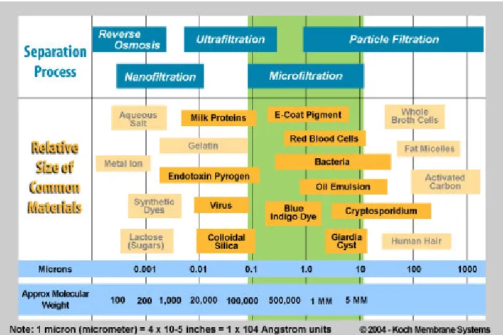
3.2.2 Micro-filtration
Figure 3.1 Separation Chart for Micro-filtration
Picture taken from(Koch Membrane Systems)
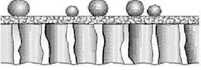
Figure 3.2 Micro-filtration Assembly
Picture taken from (Pall Corporation)
Figures 3.3a and 3.3b show how the feed water is fed into the end of the micro-filtration membranes which are secured to the head of the housing. The water is forced down the hollow fibre members under approximately 1.5 Bar where the permeate/filtrate is forced out through the membrane and the concentrate reject is removed from the other end of the hollow fibre members.
Fig
ure
3.3
a
Micro-filtration Crossflow Figure 3.3b Feedflow Process
Micro-filtration is such an effective and robust medium in the filtration of feed waters and it is a cost effective option that it is being considered and put in place on a large scale in water treatment plants (Schaefer & Griffin 2001).
3.2.3 Ultra-filtration
Ultrafiltration (UF) is a pressure driven barrier to suspended solids. It removes oils, Colloidal solids, bacteria, viruses, endotoxins, other pathogens and other soluble pollutants and allows for recycling of industrial waters to produce water with a very high purity and low silt density. It works well on waste streams with compositional variability reducing, by up to 98%, the amount of waste to be treated or discharged. It serves as a pre-treatment for surface water and seawater before reverse osmosis. A micro-porous membrane filter removes particles according to pore size. By contrast, an ultrafiltration (UF) membrane functions as a molecular sieve. It separates dissolved molecules on the basis of size by passing a solution through an infinitesimally fine filter. The ultrafilter is a tough, thin, selectively permeable membrane that retains most macromolecules above a certain size including colloids, micro-organisms and pyrogens. Smaller molecules, such as solvents and ionized contaminants, are allowed to pass into the filtrate. Thus, UF provides a retained fraction (retentate) that is rich in large
Figure 3.4 Molecular Structure of Ultrafiltration
Picture taken from (Free Drinking Water.com)
(http://www.freedrinkingwater.com/water-education/quality-water-filtration-method-ultrafiltration.htm). The removal of bacteria, viruses and pathogens makes the use of ultra-filtration ideal for the recycling of grey water.
3.2.4 Nano-filtration
preclude the formation of unwanted disinfection by-products (e.g., Trihalomethane). Nano-filtration technology can achieve a 98% recovery of water from waste. It is considered to be the state of the art in water purification. Membrane technology is rapidly gaining acceptance throughout the world as the most effective and economical water treatment method available. The degree of purification required generally determines what level of filtration is appropriate for a particular application.
3.3 Reverse Osmosis Theory
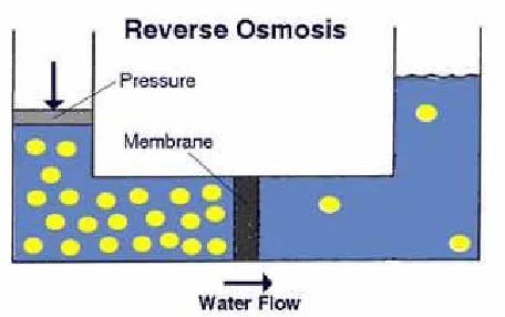
3.3.1 Osmosis
Figure 3.5 Osmosis
Picture taken from (Pure-Pro Water Corp)
3.3.2 Reverse Osmosis
Reverse Osmosis is a common treatment technology that produces high quality water. To understand reverse osmosis you have to understand the natural process of osmosis which occurs in all living cells, as previously explained. Figure 3.6 shows the separation chart for reverser osmosis. Water molecules have a stronger tendency to escape from pure water than from a salt solution. Water flows through a semipermeable membrane from the pure solution to the salt solution in an effort to equalise the osmotic pressure of the two solutions. The osmosis process may be reversed by applying pressure to the salt solution. In reverse osmosis water from the salt solution is forced back through the semipermeable membrane to the pure solution. The process stops when the osmotic pressure of the increasingly salty solution equals the applied pressure. In practise the salt solution must be continuously replaced before the osmotic pressure rises
have an inlet stream and two outlet streams. The inlet is known as the feedwater and the outlets are the Permeate (pure water) and the Concentrate (reject water).
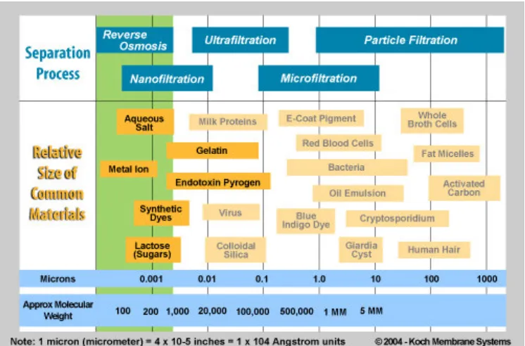
Figure 3.6 Reverse Osmosis Separation Chart
Picture taken from (Koch Membrane Systems)
through a membrane from a high salinity, or concentrated solution to the high purity, or "permeate", stream on the opposite side of the membrane. Pressure is used as the driving force for the separation. Reverse osmosis requires a high pressure to be exerted on the high concentration side of the membrane. The applied pressure (P) must be in excess of the osmotic pressure of the dissolved contaminants to allow flow across the membrane. This description of reverse osmosis summarises the concept of the technology that is the crux of the design concept of the FDSU. Figure 3.7 shows the reverse osmosis process. This process meets the minimum requirements of water treatment to produce potable water (ABCA Primary Standardization Office 1985). The amount and the quality of the filtrate/permeate/product water depends on the quality of the feedwater and on the chosen membrane.
Figure 3.7 Reverse Osmosis
3.3.3 Reverse Osmosis Membranes
The majority of the commercially manufactured reverse osmosis membranes are made from cellulose acetate, polysulfonate and polymide. Many other semipermeable
membrane used in most Reverse Osmosis systems are cast polymer films of asymmetric density, they have a dense barrier layer which is very thin supported on a more porous substrate. The pores of the membranes that the concentrate will diffuse through are 0.0001 microns in diameter, for comparison the size of a human hair is close to 100 microns thick. There is four main types of Reverse Osmosis membranes available, they include the plate and frame, hollow fibre, tubular and spiral wound. Two of the more popular membrane configurations used in Reverse Osmosis and water purification is the spiral wound membrane and the tubular disc membrane
(http://www.roconn.com/article8.html). Each of these two methods has their advantages and disadvantages which impact on their selection for specific use.
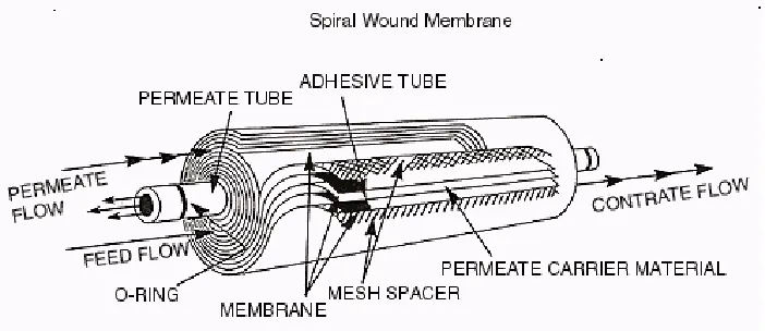
3.3.4 Spiral Wound Membranes
produce water (Amjad 1993). The membrane's operating conditions are fine-tuned to balance the amount of water which passes through the membrane, with the specific rejection rates of contaminants to achieve up to 99.8% salt rejection at low pressures and high flux rates.
Basic Construction of Spiral Wound Membranes
• Membrane cast as a film onto flat sheet • Sandwiched together with:
- Feed spacer thickness 0.028 - 0.10 inches - Permeate carrier
• Sealed at each edge and wound up around a perforated tube • Finished diameter range 2.5" to 18"
• Length options 33" to 60"
• Membranes available with sanitary net outer wrap or standard hard outer wrap • Microfiltration, Ultrafiltration, Nanofiltration and Reverse Osmosis separation ranges available
Figure 3.8 A Spiral Wound Membrane
Picture taken from (RO/CONN)
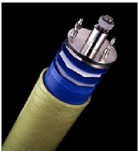
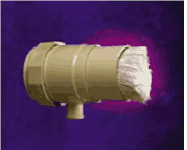
3.3.5 Disc Tube Membranes
Technology Description: The Disc Tube Module (DTM) technology is an
fouling and scaling of the membranes. Suspended particulates are readily flushed away from the membrane during operation. The high flow velocity, short feed water path across each membrane, and the circuitous flow path create turbulent mixing to reduce boundary layer effects and minimize membrane fouling and scaling. The DTM design allows easy cleaning and maintenance of the membranes. Membrane material for the DTM is formed into a cushion with a porous spacer material on the inside. The membrane cushions are alternately stacked with hydraulic discs on a tension rod. The hydraulic discs support the membranes and provide flow channels to pass the feed liquid over the membranes. After passing through the membrane material, permeate flows through permeate collection channels to a product recovery tank. A stack of cushions and discs is housed in a pressure vessel. Flanges seal the ends of the module in the pressure vessel and provide the feed water input and the product and reject output connections. Figure 3.9a and 3.9b show the Disc Tube assembly and components. The number of discs per module, number of modules, and the membrane materials can be custom designed to suit the application. Modules are typically combined in a treatment unit or stage. The DTM technology can use reverse osmosis, ultrafiltration, or micro-filtration membrane materials. These membranes are more permeable to water than to contaminants or impurities. Water in the feed is forced through these membranes by pressure and becomes permeate consisting of a larger fraction of water with a lower concentration of contaminants. The impurities are selectively rejected by the membranes and are thus concentrated in the smaller fraction of the concentrate left behind. The percentage of water that passes through the membranes is a function of the operating pressure, membrane type, and concentration of the contaminants
Figure 3.9(a) A Disc Tube Assembly Figure 3.9(b) A Disc Tube Component
Picture taken from (Pall Corporation)
[image:44.612.165.302.43.193.2]Chapter 4
Dual Membrane Design Requirements
In order to meet the project aim of designing a safer, more reliable, robuster and more versatile Field Deployable Shower Unit than is currently available in the market place for use by the Department of Defence certain design requirements have been identified by Defence. These design requirements will dictate the design needs of the Deployable Field Shower Unit.
4.1 Feedwater Sources and Collection
springs providing that the Total Dissolved Solids (TDS) of the feedwater does not exceed 20,000 mg/L. It will also be designed with an over engineered capability of being able to accept feedwater with a TDS of up to 35,000 mg/L which includes water sources of estuaries and open sea. This design concept is for as occasion dictates and it is not the primary role of the FDSU. The feedwater will initially be tested by an Army Engineer or Medical Corps personnel to ascertain the turbidity and the TDS levels of the water to ensure they are within the TDS level of 20,0000 mg/L for use. As well as this initial water test the FDSU system will conduct a full analysis of the water during run up and continually monitor the water condition from start to finish
4.2 Water Standards
4.3 Production Requirements
The scope of requirement states that eight personnel have to be able to bathe at any one time and that the rate of 80 personnel per hour showering must also be achieved. On top of this requirement the FDSU must capable of operating continually for up to ten hours. Based on these requirements and assuming the worst case scenario of water with a TDS of 20,000 mg/L where the resultant permeate is 60% and concentrate is 40% of the feedwater through the Reverse Osmosis Membranes and the permeate is 90% and the concentrate is 10% of the feedwater through the micro-filter membranes then when the system is run up and operational there will be a requirement of 3,896 litres of feedwater per hour to be supplied to the FDSU. The feedwater supply requirements are varying in accordance with as to what the supply is and depending on the percentage of permeate that is produced through the Reverse Osmosis membranes and the Micro-filter
4.4 Operability
The FDSU is designed to be an automated system operated by Programmable Logic Controller (PLC). The whole system will be automated apart from the cleaning sequence which will be started manually and then fully PLC controlled after initiation of the sequence. The system under the operation of the PLC will continually monitor the standard of the water for pressure, chlorine, temperature, pH, conductivity, turbidity, TDS, salinity and flow through sensors that will transmit the information back to the PLC processor. The processor monitors the sensors and has a fail-safe control where the system turns off in the event of the following circumstances; feed water pressure at the high pressure pump inlet falls below 0.5 bar, the working pressure in the Reverse Osmosis module exceed 75 bar, electric motors overload, pressure in the permeate discharge line exceeds 3 bar, pressure in the concentrate discharge line exceeds 5 bar, malfunction of the motorized pressure control valve and excessive salinity of potable water. In the event of excessive salinity in the permeate water a diverter valve directs the water away from the shower system.
4.5 Maintenance
contractor when back in barracks. The FDSU is designed with a large amount of commonality of sub-assemblies and parts with the water purification unit resulting in cross training that will benefit the maintainers. The majority of parts will be replaced by a one for one exchange. This will include sensors, small dosing pumps,
instrumentation, valves, micro-filter membranes and Reverse Osmosis membranes that can not be repaired by the field repair kit.
4.6 Cleaning Regime
For the FDSU to meet its operational requirements it is paramount that it is cleaned and maintained on a regular basis. As the adage goes prevention is better than cure. In the majority of Reverse Osmosis systems, membrane blinding and fouling is the main cause of reduction in membrane life. The cross flow of the disc tube membrane help to alleviate a lot of this, however they still require chemical cleaning every 700 hours. The micro-filter membranes are air scrubbed and back flushed on a regular cyclic routine or when the differential pressure exceeds a pre-determined limit. They also require a chemical clean. The air scrubbing and back flushing of the micro-filters will be
controlled by the PLC. The chemical cleaning of both the micro-filter and the disc tube modules will be controlled by the operator.
4.7 Sub-assemblies and Components
The FDSU will contain sub-assemblies as well as a number of components that will have to be monitored for their condition and replacement in line with the maintenance policy. Sub-assemblies such as generators, pumps and compressors will need to be technically inspected and serviced on a regular basis. This will mean down time of the FDSU which will need to be considered when the FDSU is in operation. Components are more along the lines of consumable which are easier to replace on a one for one basis. This would include membranes (micro-filter and disc tube), sensors, dosing pumps and valves. The consumption of the components will be largely dependant on the quality of the feed water that is being used and on the maintenance schedule that is adopted and adhered to.
4.8 Transportation and Containment
4.9 Selected Micro-filtration Membrane
The micro-filter membrane that has been chosen for the FDSU is the Pall Microza membrane system. The features of the Microza membranes are that they were
developed for treatment of water for process and municipal applications, replacement of multi-media and other filters, protection against bacteria and virus contamination, removal of organic and colloidal contaminants such as silica, and the protection of Reverse Osmosis system. The Microza membrane in micro-filtration is a PVDF 0.1 micron membrane, it has high permeability and throughput (recovery rates can be >95%), robust membrane fibre material, removes turbidity, oxidised iron and
[image:51.612.132.314.513.659.2] [image:51.612.386.539.513.665.2]4.10 Selected Reverse Osmosis Membrane
The Reverse Osmosis membrane selected for use in the Field Deployable Shower Unit is the Pall Disc Tube™ Module System. It has been selected due to its major advance in Reverse Osmosis technology and also due to the fact that the Australian Navy use the system on their fleet of ships for water purification. This allows for commonality of parts between the FDSU and the Navy water purification/Desalination systems. The patented fluid dynamics and construction of the disc membrane stack result in an open channel, unrestricted and fully turbulent feedwater system. This means that suspended solids carried in the feedwater cannot be trapped or easily settle out inside the
membrane module. In frequent maintenance, cleaning of the membranes can be
successfully achieved using a standard, built-in system. Round-the-clock reliability and product water quality are also guaranteed. These are achieved through Pall's adherence to the highest standards in components, materials, and methods of design and
construction. Advantages of the Disc Tube Module System include:
Minimization of membrane scaling and fouling. The system uses short feed flow paths, open channels and high-packing densities to minimize concentration polarization and physical flow impediments. Consequently, scaling and fouling are greatly reduced while high energy efficiency is maintained.
Lower membrane replacement costs. Compared to spirally wound and hollow fibre membrane elements which are life-sealed at manufacture (so the complete element must be replaced at relatively high cost), the DT Module system allows the replacement of individual sheets of membrane at a fraction of the cost. Thus allowing the system to be repaired in the field.
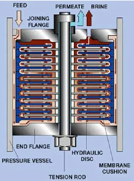
Figure 4.2 - Crosscut View of Disc Tube Assembly
Picture taken from (Pall Corporation)
Easy access to all membranes. Modules can easily be opened up to permit replacement or inspection of each membrane cushion.
Compact and flexible. Modular design and construction of all standard units simplifies transportation and installation, and enables efficient use of floor space. Also the DT modules can be installed in either the horizontal or the vertical position.
4.11 Pumps
The processes involved in the FDSU involves the use of water at low and high pressure. The lower pressure being the pump feeding the water to the micro-filter system at approximately 1.5 bar. The High Pressure pump feeds the water to the Reverse
Chapter 5
Project Design Methodology
5.1 Project Research
A thorough, comprehensive and systematic investigation of technical manuals, engineering notes, technical and engineering electronic data bases as well as
communication with industry professionals will be undertaken. To complement this investigation a general internet search will be conducted as well as a review of relevant regulations, Defence Manuals and notes. To correlate and consolidate all of the gathered information, meetings and discussions with industry group subject matter experts will be co-ordinated and conducted.
5.2 Conceptual Design of the Field Deployable Shower Unit
Following the conceptual design of the FDSU the components, parts, consumables and equipment requirements can be fully investigated, identified and sourced based on the specifications which they must meet. As the FDSU will be part of the Department of Defence equipment fleet, specific items and equipments like pumps, motors, generators, membranes, filters, hoses etc will be selected to replicate current and existing parts and equipment being used within Defence. This will provide commonality of those parts and equipment throughout Defence and provide savings in the cost of parts,
Chapter 6
Field Deployable Shower Unit
[image:57.612.81.523.234.510.2]6.1 Concept of Operations
Figure 6.1 – FDSU General Concept of Operations
pumped by the micro-filtration pump at 1.5 Bar through the micro-filter assembly and into the filtrate tank where it is dosed with sodium bisulphate to neutralise the chlorine as the chlorine is detrimental to the reverse osmosis Disc Tube membranes. The backflush pump is only operated during the clean cycle of the micro-filter assembly. The water is then pumped via the high pressure (HP) pump at 45 Bar under the control of the motor control valve to the permeate tank prior to passing through the carbon filter and onto the shower system.
6.2 Input System and Treatment
The input system is designed to remove any larger particulate, sediments, foliage or any other debris from the feed water and thus ensuring it does not make its way to the micro-filter membranes. The water is tested and assessed for its suitability prior to it being pumped into the FDSU. The onboard PLC will analyse the suitability of the water also to ensure it’s within TDS and turbidity parameters.
6.2.1 Input Design
and chlorine levels. Based on the readings from S3 and S4 the feedwater will be dosed with the required amount of Chlorine through DP1 and the Ph will be kept at a neutral pH (~7) by acid dosing through DP2. The level of the water in PFT1 will be monitored by level control S5. If the level of PFT1 is too low S5 will send a signal to the PLC which won’t allow any feed water to be pumped from PFT1 by pump P2.
[image:59.612.134.516.286.682.2]6.2.2 Input Pump and Strainer
An external single stage centrifugal pump that is attached to an 800 micron strainer pumps the feed water to the FDSU. The pump has the capacity of pumping from up to 100m away and has a lift capacity of an elevation of five metres. The input strainer will be attached to a floating buoy if the feed water source is from a dam, lake or river. Once the feed water passes through the strainer it is pumped to the back flushable filter which filters up to 400 microns. The back flushable filter can be set to carry out a back flush and clean whenever a pre determined differential pressure is achieved or on a cleaning cycle to maximise operational time of the FDSU. The feed water is then pumped to the Micro-filter system by the Micro-filter pump at a pressure of 1.5 bar.
6.2.3 Chlorine and Acid Dosing
Before the water is dosed with Chlorine or an acid it is tested for its Chlorine and pH levels to ascertain the feed waters current levels of both. The Chlorine is added for an initial disinfection of the feed water. The micro-filter membranes are robust and are not affected by or damaged by the chlorine in the water. The feed water pH level is
checked and dosed with an acid if required to maintain a neutral pH level of around about 7.
6.3 Micro-filtration System
micro-filter pump. Particulate that is removed by micro-filtration includes turbidity, oxidised iron and manganese, colloids and is a dependable barrier against
Cryptosporidium, Giardia Lamblia, Legionella and other bacteria.
6.3.1 Micro-filter System
The feed water is fed from the input system by P2. As the water is being pumped to the micro-filtration system it is tested by S10, S11, S12 and S13 which tests the pH, Chlorine level, temperature and inlet pressure of the water. P2 raises the water pressure to 1.5 bar. The water is pumped through V10. If the water is unsuitable P2 will stop and V10 will redirect the water to the drain disposal waste. If the water is suitable the feed water will pass through V10 en-route to the MF array of MFB1. The 1.5 bar pressure forces the feed water through MFB1 and the permeate flows through V11 to filtrate tank FT10. The concentrate is discarded to the drain disposal waste via V14and S14. The water enroute to FT10 is tested by S16 for the level of chlorine in the water and is then dosed with sodium bisulfite by DP11 to neutralise the chlorine prior to the feed water being pumped to the Reverse Osmosis system by high pressure pump HP1. If the differential pressure between S14 and S11 is greater than 3 bar an automatic backwash will be initiated on the micro-filter system. If the chlorine level sensed by S18 is too high then V13 will redirect the water to the drain tank and the PLC will initiate rectification action.
Figure 6.3 Micro-filter System
6.3.2 Micro-filter System Backwash Process
6.4 Reverse Osmosis System
The Reverse Osmosis system is the crucial component of the FDSU for the removal of the remaining particulate that is left in the feed water. The high pressure pump has raised the feed water pressure to 45 bar and forces the pre filtered and treated water through the Reverse Osmosis system.
6.4.1 Reverse Osmosis System Design
HP1 raises the pressure of the feed water to 45 bar. S21 tests the feed water for its Chlorine level. If the Chlorine level is too high then V20 and pressure reducing valve V31 will redirect the feed water away from HP1 and through to drain disposal tank DDT1. If the feed water is suitable it is forced into the Reverse Osmosis system RO1 through V21, V22, S22, S23 and S24. Initially the High Pressure Pump HP1
shower or to DDT1 depending upon the quality of the Permeate after it has been checked by the sensors for pH, TDS, salinity, conductivity and turbidity.
[image:64.612.135.526.209.453.2]Refer to figure 6.4 for a sketch of the Reverse Osmosis system. Appendix E provides a component description.
Figure 6.4 Reverse Osmosis System
6.4.2 Membrane System
V26 will open and drain the water to the drain tank through the pressure reducing valve V27 which reduces the pressure to a safer operating pressure before it drains away. Once MCV1 allows the water to flow the permeate will be controlled by SCV1. If the sensors assess the pH, TDS, salinity, conductivity and turbidity to be of a potable standard then the water will be directed to the shower system. If the water is not of a potable standard then SCV1 will direct it to the drain tank. The concentrated waste will pass through V30, MCV1 and pressure reducing valve V29 which reduces the water pressure to a safe operating pressure and drains the water to the drain tank. The membrane system consists of 8 Disc Tube membranes which provides the calculated water requirements. Each of the Disc Tube membranes has its own individual input and output lines complete with shut off valves. This capability will enable the isolation of individual membranes to conduct maintenance and repairs as required.
6.5 Post Reverse Osmosis Treatment
The final part of the FDSU system is the post Reverse Osmosis treatment where the feed water goes through its final processing stage prior to being utilised in the shower system, to where it is then reclaimed and recycled to be passed back into the input stage to go through the complete FDSU process again. This process is going to be developed further in future work, however, a basic concept is provided below.
6.5.1 Post Reverse Osmosis Design
the water to a neutral level. The water from PT1 is pumped via P41 through a carbon cartridge filter CCF1 to the shower system where it is delivered to eight shower heads for use. The spent shower water is then drained to shower sump SS1. From the SS1 the water is pumped through P42 through back flushable filter BFF41 and V45 to the input feed tank MFT1 for re-use in the DFSO system. Figure 6.5 shows the post reverse osmosis system general concept
Figure 6.5 Post Reverse Osmosis System
6.6 Chemical Dosing and Cleaning
6.6.1 Chemical Dosing
The system requires that the feedwater is treated by various chemical to ensure that it is at a disinfected and potable standard at the end of the FDSU process. Variable dosing pumps are used to treat the water with Sodium Bisulphate, Chlorine and Sodium
is controlled by the PLC. It senses the water condition through the respective sensors and adjusts the dosing based on the sensor reading. It is initiated and completed in real time.
6.6.2 Chemical Cleaning
Chapter 7
Design Modification Additions
The FDSU design had certain design modifications added to it as the design process progressed before the final concept was decided upon. The modifications came about as a consequence of the thorough and comprehensive research that was undertaken. That is particular technologies that were researched after a particular technology had been selected for a particular function were found to be more suitable and appropriate for that particular function in the design.
7.1 Reverse Osmosis Membranes
Initially the spiral wound membranes were selected for the reverse osmosis system based on their large surface area and throughput of permeate. After significant research and assessing the application of the reverse osmosis membranes the Disc Tube
membranes were selected. The Disc Tube membranes were selected due to their ease of use; practicality in their compactness and the fact that they can be installed either in the vertical or horizontal configuration, the open feed channel, unrestricted and turbulent feed water system assisting in its self cleaning which results in the Disc Tube
7.2 Micro-filtration Membranes
Chapter 8
Resource Analysis
The Field Deployable Shower Unit has been designed based on current technology and proven systems that are currently in service in industry. Based on these technologies and the current water purification unit that the Department of Defence has in service, components, parts and sub-assemblies that are common between the FDSU and the water purification unit will be sourced from Pall Australia who supply the water purification unit to the Department of Defence.
Where common parts are not available then suppliers of commercial of the shelf (COTS) parts have been sourced. All selected manufacturers and suppliers are well established within their respective industries and are at the forefront of their industry in technology and manufacturing. The majority of them are also global which will satisfy the requirement of obtaining parts if the FDSU has to be deployed away from Australia.
8.1 Micro-filtration Membranes (Pall Microza Membranes)
used as pre-treatment for surface water and seawater before reverse osmosis and other membrane systems, (http://www.gewater.com/products/equipment/mf_uf_mbr/mf.jsp). Microza high permeability 0.1 micron hollow fibre membranes offer a major advantage in drinking water filtration applications, including the protection of RO systems used in harsh conditions or with difficult feed waters. The surface filtration membrane prevents pore plugging across a high surface area, has good chemical and mechanical strength and with its own self cleaning backwash system, typically provides up to five years service life. Systems are modular and therefore adaptable to any flow requirement and space restriction.
Figure 8.1 Pall Microza Micro-filter Assembly
Picture taken from (Pall Corporation)
8.2 Reverse Osmosis Membrane Filters (Pall)
Figure 8.2 Pall Disc Tube Module
Picture taken from (Pall Corporation)
The Pall DT Module is designed to overcome many of the problems associated with existing reverse osmosis desalination systems
(http://www.pall.com/Aerospace_24350.asp). Features include:
• High performance and low operating costs.
• Modular construction for installation into available spaces.
• Worldwide service network with 20 years experience on membrane systems.
• Unrestricted, open channel, turbulent feedwater flow.
• No chemical pre- treatment required.
• High permeate recovery rates.
• Low environmental impact.
• Integrated self cleaning system.
• Simple and flexible maintenance procedures.
• Quick, simple installation.
8.3 Valves and Pneumatic Actuators
The check and shut off valves will be sourced from Crane Australia
[image:73.612.159.421.354.486.2](http://www.craneaus.com.au/index.html). The valve product is a bronze cast valve and contains approximately 90% copper, 6% tin and 4% zinc making it ideal for its use in the DFSU due to its resistance to wear and corrosion.
Figure 8.3 Crane Check and Shut Off Valves
Picture taken from (Crane Australia)
for process automation led to the development and production of accessories, such as switch boxes and specialised solenoid valves In 1999 Emerson Electric, an American multinational conglomerate consisting of more than 300 companies and divisions, acquired the company in 1999
[image:74.612.152.534.223.385.2](http://www.emersonprocess.com/valveautomation/hytork/). Some examples of Hytorks actuators are displayed in figure 8.4.
Figure 8.4 Pneumatic Actuators
Picture taken from (Hytork)
8.4 Pumps
model is matched with Relief Valves and Pulsation Dampeners or can be customized into a Power Unit designed specifically for your high pressure desalination system (http://www.catpumps.com/pages/Pumps_ss_desal.asp). Figure 8.5 shows the 6767 pump that will be used. These pumps are also used on the Australian Navy’s desalination units.
Figure 8.5 Cat Model 6767 High Pressure Pump
Picture taken from (Cat Pumps)
8.5 Pressure Relief and Reducing Valves
and approved distributors, Mack Valves offers customers the highest levels of technical support and customer service (http://www.mackvalves.com.au).
They are fabricated from bronze and stainless steel and are specifically designed for use in saltwater conditions. This may appear to be over engineering with the FDSU but as the system is designed to operate with brackish water this is not detrimental in fact it will increase its life of type.
Figure 8.6(a) Mack Pressure Reducing Valves. Figure 8.6(b) Mack Pressure Relief Valve
Picture taken from (Mack Valves)
8.6 Power Requirements
[image:76.612.132.255.246.362.2]DURABILITY
Constructed for rugged conditions and developed to stringent military requirements for the Australian Army, the APD 016 has undergone comprehensive testing and survived extremes in temperature, humidity, salt laden atmospheres, vibration, and drop tests.
POWER OUTPUT
The APD 016 is a skid-mounted field deployable diesel generator capable of delivering 16 kVA for any application in the harshest of environmental conditions. With
exceptional motor-starting capability, the APD 016 is able to start 3-phase motors up to 12 kW DOL and will also prov