322 ACI Structural Journal/March-April 2000 ACI Structural Journal, V. 97, No. 2, March-April 2000.
MS No. 99-032 received January 8, 1999, and reviewed under Institute publication policies. Copyright 2000, American Concrete Institute. All rights reserved, includ-ing the makinclud-ing of copies unless permission is obtained from the copyright proprietors. Pertinent discussion will be published in the January-February 2001 ACI Structural Journal if received by September 1, 2000.
ACI STRUCTURAL JOURNAL
TECHNICAL PAPER
This paper presents a performance based evolutionary topology optimization method for automatically generating optimal strut-and-tie models in reinforced concrete structures with displace-ment constraints. In the proposed approach, the eledisplace-ment virtual strain energy is calculated for element removal, while a perfor-mance index is used to monitor the evolutionary optimization process. By systematically removing elements that have the least contribution to the stiffness from the discretized concrete member, the load transfer mechanism in the member is gradu-ally characterized by the remaining elements. The optimal topology of the strut-and-tie model is determined from the per-formance index history, based on the optimization criterion of minimizing the weight of the structure while the constrained displacements are within acceptable limits. Several examples are provided to demon strate the capability of the proposed method in finding the actual load transfer mechanism in concrete members. It is shown that the proposed optimization procedure can produce optimal strut-and-tie models that are supported by the existing analytical solutions and experimental evidence, and can be used in practice, especially in the design of complex rein-forced concrete members where no previous experience is avail-able.
Keywords: corbels; deep beams; performance; reinforced concretes.
INTRODUCTION
The strut-and-tie model is considered the basic tool in the de-sign and detailing of reinforced concrete members loaded in bending, shear, and torsion. The structural idealization of a re-inforced concrete member is to develop an analogous truss model consisting of compressive struts and tensile ties that rep-resent the actual load transfer mechanism in the concrete mem-ber for the applied loads and given support environments. The strut-and-tie model developed is then employed to investigate the equilibrium between the loads, the reactions, and the inter-nal forces in the concrete struts and in the reinforcements (Marti1). The actual load carried by the strut-and-tie model is treated as a lower-bound ultimate load for the reinforced con-crete member based on the lower-bound theorem of plasticity. This simple approach provides a clear understanding of the be-havior of reinforced concrete members.2 Moreover, it offers a unified, intelligible, rational, and safe design framework for structural concrete under combined load effects.3
The truss models with 45-degree inclined compressive diag-onals were originally developed by Ritter4 for the analysis and design of reinforced concrete beams under shear in 1899. Later, Mörsch5 extended the truss models to the design of reinforced concrete members under torsion. Recently, the consistent de-sign approach proposed by Schlaich et al.2,6 allows any part of a concrete structure to be designed using the strut-and-tie mod-eling. The truss model approach is also recommended by the
ASCE-ACI Committee 445 on Shear and Torsion3 for the shear design of structural concrete. Based on this approach, develop-ing an appropriate strut-and-tie model in the structural concrete member is an important task for the structural designer. The elastic stress distribution and load path methods have been used to develop strut-and-tie models in structural concrete.1,2 In the elastic stress distribution approach, the strut-and-tie model is formed by orientating the struts and ties to the principle stress flows, which are obtained by performing a linear elastic finite element analysis on the uncracked homogenization concrete member. It is difficult, however, to find the correct models in concrete members with complex loading and geometry condi-tions using these conventional methods that usually involve a trial-and-adjustment process.
The layout optimization theory has been well-developed in the past few decades (Rozvany et al.;7 Topping8). Kumar9 and Biondini et al.10 used the truss topology optimization tech-niques to find optimal strut-and-tie models in structural concrete members based on the ground structure approach. The continu-um concrete member is represented by a ground structure that consists of many truss members, and the linear programming technique is employed to solve the truss topology optimization problem. This method offers an automatic search for strut-and-tie models in reinforced concrete members in an iterative pro-cess. Since the ground structure grid has a significant effect on the optimal topology of the structure,11 however, the chosen ground structure may not adequately simulate the nature of a continuum concrete member.
The topology optimization of continuum structures has re-ceived considerable attention in recent years. The homogeniza-tion method (Bendsøe and Kikuchi12) has been proposed by treating topology optimization as a material redistribution prob-lem within a fixed continuum design domain. The solid isotro-pic microstructure with penalty (SIMP) method (Zhou and Rozvany;13 Rozvany et al.14) for intermediate densities can be used to generate solid-empty type topologies for continuum structures. The evolutionary structural optimization (ESO) method (Xie and Steven;15-17 Chu et al.18) is developed based on material removal criteria. The performance indexes devel-oped by Liang et al.19-21 are used to monitor the optimization process, and to measure the performance of structural topolo-gies and shapes generated by different structural optimization methods. The optimal topology of a plane stress continuum structure produced by the continuum topology optimization is often a truss-like structure. Therefore, it is appropriate to apply Title no. 97-S36
Topology Optimization of Strut-and-Tie Models in
Reinforced Concrete Structures Using an Evolutionary
Procedure
323 ACI Structural Journal/March-April 2000
this technique in finding the best strut-and-tie models in rein-forced concrete structures.
In this paper, a performance based evolutionary topology optimization method based on the stiffness formulation is pro-posed and applied to automatically developing optimal strut-and-tie models in reinforced concrete structures. The key fea-tures of the present topology optimization method are outlined. Examples are provided to show the effectiveness and validity of the proposed design optimization procedure in automatically tracing the actual load transfer mechanism in concrete deep beams, with and without web openings, slender beams, and a corbel. The optimal strut-and-tie models obtained by the present study are qualitatively compared with existing analytical solu-tions and experimental observasolu-tions. The results and various re-lated aspects are discussed.
RESEARCH SIGNIFICANCE
Although the potential of modern structural optimization techniques has been realized by aeronautical, automotive, and mechanical industries, they are still viewed by civil engineers as academic exercises.22 It should be esteemed, however, that structural optimization can be much more than weight savings. Structural optimization techniques can be used to find better to-pologies and shapes for the design of civil engineering struc-tures. The present research exposes the capability of an evolutionary topology optimization method for producing opti-mal strut-and-tie models in concrete members to civil engineers. Extensive work has been undertaken on shear in structural con-crete, but the shear behavior of a reinforced concrete member is still difficult to understand due to its complicated nature. The load trans-fer mechanism of a reinforced concrete member is not the function of a single variable, and it depends on the geometry, loading, and support conditions of the member. It is time consuming and diffi-cult for the structural designer to find appropriate strut-and-tie models in complex members by using conventional methods. Therefore, the proposed automatic design optimization procedure is not only helpful for concrete researchers to understand the shear resistance mechanism, but also a valuable design tool for concrete designers in the design and detailing of reinforced concrete mem-bers using the strut-and-tie modeling.
PERFORMANCE BASED EVOLUTIONARY OPTIMIZATION
Problem formulation
The topology optimization of a continuum structure is to find the optimal geometry that minimizes the weight of the structure under the applied loads while satisfying the requirement of con-straints imposed on the structure. The optimization problem can be stated as follows
(1)
(2)
where W is the total weight of the structure; we is the weight of
the e th element; te is the thickness of the e th element that is treated as the design variables; uj is the absolute value of the jth constrained displacement; uj* is the prescribed limit of uj; m is the total number of displacement constraints; and n is the total number of elements within the structure.
It is known that some part of materials in the initial design do-main is inefficient in carrying loads. The optimization task is to identify the inefficient materials and to remove them from the structure so that the objective of minimizing the weight can be achieved while the constrained displacements are within the prescribed limits. By means of systematically removing ele-ments from the discretized concrete member, the actual load paths within the concrete member can be gradually character-ized by the remaining elements. In detail design, the concrete usually remains in the structural member. Hence, the strut-and-tie idealization of a reinforced concrete member offers a conser-vative design.
Element removal criteria
For structures subject to displacement constraints, it is desir-able to eliminate elements that have a minimum effect on the changes in the constrained displacements from the design. The effect of element removal on the constrained displacements can be evaluated by the element sensitivity numbers, which are cal-culated from the results of the finite element analysis. In the fi-nite element analysis, the equilibrium equation for a static structure is expressed by
(3)
in which [ K] is the stiffness matrix of the structure; {u} is the nodal displacement vector; and {P} is the nodal load vector. When the eth element is removed from a structure, the stiffness and displacements are changed, and Eq. (3) can be rewritten as
(4)
where [∆K ] is the change of stiffness matrix, and {∆u} is the change of displacement vector. The change of the stiffness ma-trix due to the removal of the eth element is
(5)
in which [Kr] is the stiffness matrix of the resulting structure, and [ke] is the stiffness matrix of the e th element. The change of displacement vector can be obtained by subtracting Eq. (3) from Eq. (4) and neglecting the higher-order term as
(6)
To measure the change of the constrained displacement uj due to an element removal, a virtual unit load is applied to the posi-tion of the j th constrained displacement. By multiplying Eq. (6) with the virtual unit load vector {Fj}T, the change of the
con-strained displacement is
(7) minimize W we( )te
e=1 n
∑
=
subject to uj–uj∗≤0 j = 1 2, ,…,m
K
[ ]{ }u = { }P
K
[ ]+[∆K]
( )({ }u +{∆u}) = { }P
∆K
[ ] = [ ]Kr –[ ]K = –[ ]ke
∆u
{ } = –[ ]K –1[∆K]{ }u
∆uj = (–{ }Fj T[ ]K –1[∆K]{ }u )
ACI member Qing Quan Liang is a Research Associate in the School of Civil Engineer-ing and Environment at University of Western Sydney, Australia. He graduated from the Architectural Engineering Institute of Guangdong, China, in 1986, and received his ME in civil engineering from the University of Wollongong, Australia, in 1998. His research interests include structural concrete, stability and strength of composite steel-concrete members, and structural optimization.
Yi Min Xie is an associate professor in the School of the Built Environment at Victo-ria University of Technology. He graduated from the Shanghai Jiao Tong University, China, in 1984, and received his PhD from the University of Wales at Swansea, UK, in 1990. His research interests include computational mechanics and structural optimi-zation.
324 ACI Structural Journal/March-April 2000
325
where {uj} and {uej} are the nodal displacement vectors of the structure and the eth element under the virtual unit load, respec-tively; and {ue} is the displacement vector of the eth element un-der the real loads. Equation (7) indicates the change in the constrained displacement due to the removal of the eth element, and can be used as a measure of the element efficiency. Therefore, the virtual strain energy for the eth element in the design subject to a displacement constraint is denoted by
(8)
For a structure under multiple displacement constraints, the weighted average approach is used to calculate the virtual strain energy for element removal. The virtual strain energy for the eth element for multiple displacement constraints is determined by
(9)
where the weighting parameter λj is defined as uj/uj*. If the con-strained displacement is far from the prescribed limit, it will be less critical in the optimization process.
The elements with the lowest sensitivity numbers have little effect on the changes in the constrained displacements, and can be removed from the structure to obtain an efficient design. For a structure under multiple load cases, only elements having the lowest sensitivity numbers for all load cases are eliminated from the design. This ensures that remaining materials in the structure can safely carry all the loads. It is noted that minimizing the changes in constrained displacements is equivalent to maximiz-ing the stiffness of the structure. Since concrete permits only limited plastic deformation, the best strut-and-tie model within the concrete member is the one with the maximum stiffness or minimum deflections, while its weight is the minimum.2,9,23 Therefore, the optimization method based on displacement for-mulation is appropriate for finding optimal strut-and-tie models.
Performance index
In topology optimization, the cycle of finite element analysis and element removal is repeated, and the quality of the resulting structure is gradually improved. The performance of the resulting topology at each iteration is evaluated by the performance index that can be derived by the scaling design approach.20
For a linear elastic plane stress continuum structure, the stiff-ness matrix is a linear function of the design variable such as the element thickness, which has a significant effect on constrained displacements and the weight of the final optimal design. To ob-tain the best feasible topology of a structure with the minimum weight, the thickness of elements can be scaled at each iteration in the optimization process so that the critical constrained dis-placement always reaches the prescribed limit.24,25 By scaling the initial design domain with a factor of u0j/uj*, the scaled weight of the initial design domain can be expressed by
(10)
where W0 is the actual weight of the initial design domain, and u0j is the absolute value of the j th constrained displacement that is the most critical in the initial design under real loads. Similar-ly, by scaling the current design with respect to the most critical
uj
{ }T
∆K
[ ]{ }u
– {ue j}T[ ]ke { }ue
= =
αe = {ue j}T[ ]ke { }ue
αe λj{ue j} T
ke
[ ]{ }ue
j=1 m
∑
=
W0s u0j uj∗
--- W
0 =
displacement limit, the scaled weight of the current design at the ith iteration is represented by
(11)
where uij is the absolute value of the jth constrained displace-ment that is the most critical in the current design at the ith iter-ation under real loads, and Wi is the actual weight of the current design at the ith iteration.
The efficiency of material layout in a structure at the ith it-eration can be measured by the performance index, which is defined as
(12)
It is seen from Eq. (12) that the performance index is a dimen-sionless number that measures the efficiency of material layout in resisting the deflection and failure of a structure. The perfor-mance of a structural topology is improved by removing mate-rials having the least contribution to the stiffness from the structure. The objective of minimizing the weight of a structure with displacement constraints can be achieved by maximizing the performance index in an optimization process. The peak val-ue of the performance index indicates that the best structure is the one with the minimum weight and deflection, as pointed out by Hemp.23 The displacement limit uj* is eliminated from Eq. (12). This means that the optimal topology does not depend on the magnitude of the displacement limits. Therefore, displace-ment limits are set to large values in the optimization process in the present study to obtain the optimal topology, which can then be sized by changing the width of the member with respect to the actual displacement limits.
It is worth noting that changing the element thickness has no effect on the topology of the structure or on the performance in-dex, but it has a significant influence on the weight of the struc-ture and the constrained displacements. As a result of this, it is not necessary to change the thickness of elements in the model in the finite element analysis at each iteration. The performance index can be employed to evaluate the efficiency of the resulting topology at each iteration and to identify the optimum, which can then be sized by changing the thickness of the structure to satisfy the actual displacement limit.
Evolutionary optimization procedure
The design of a reinforced concrete member by using strut-and-tie models usually involves the estimation of an initial size, finding an appropriate strut-and-tie model, and dimensioning struts, ties, and nodes. Developing an appropriate strut-and-tie model for a complex concrete member is perhaps the most dif-ficult task in the design process. Afterwards, dimensioning the truss model is straightforward according to codes of practice,26 and is not the objective of this paper. Interested readers should refer to References 1 and 2 for details. The present topology op-timization method can be used for developing the best strut-and-tie models in concrete members in the design process. The opti-mization procedure is given as follows:
Step 1: Model the concrete member with fine finite elements; Step 2: Analyze the concrete member for real loads and virtu-al unit loads;
Step 3: Calculate the performance index using Eq. (12); Step 4: Calculate the virtual strain energy for each element using Eq. (8) or (9);
Step 5: Delete a small number of elements with the lowest vir-tual strain energy; and
Wis
ui j
uj∗
--- W
i =
P I W0
s
Wis
--- u0jW0 ui jWi
ACI Structural Journal/March-April 2000 326 Step 6: Repeat Steps 2 to 5 until the performance index is less
than unity.
The performance index is used as an indicator of material ef-ficiency and as the termination criterion in the previously men-tioned iterative optimization process. Because the virtual strain energy is calculated by neglecting the higher-order term in the sensitivity analysis, only a small number of elements is removed from the structure at each iteration to obtain a sound solution. The element removal ratio (ERR) is defined as the ratio of the number of elements to be removed to the total number of ele-ments in the initial design domain and kept constant in the opti-mization process. It is obvious that the accuracy of the solution is improved by adopting a smaller element removal ratio, but the computational cost will be considerably increased. It has been found that the ERR of 1 or 2% provides reasonable results for use in engineering practice.
After extensive cracking of concrete, the loads applied to a re-inforced concrete member are mainly carried by compressive concrete struts and tensile steel reinforcements. The failure of a reinforced concrete member cannot simply be explained by the tensile stresses attaining the tensile strength of concrete; rather, it is due to the breakdown of the load transfer mechanism at the crack.3 In current engineering practice, the behavior of rein-forced concrete members is usually approximated by un-cracked, cracked linear and limit analyses.27 Strut-and-tie models are primarily used to predict the behavior of fully cracked structural concrete members under the ultimate load condition. Because the locations of tensile ties and the amounts of steel reinforcement are not known in advance, the concrete member is modeled using plane stress elements in the present study. The linear elastic behavior of cracked concrete is as-sumed in the analysis as suggested by Schlaich et al.2 Because tensile ties in the strut-and-tie model obtained will be replaced with steel reinforcements in a reinforced concrete member, the effect of cracking due to stresses attaining the tensile strength of concrete is not considered. The progressive cracking of a con-crete member, however, is characterized by gradually removing concrete from the member that is fully cracked at the optimum. In nature, the loads are transmitted so that the associated strain energy is a minimum. The topology optimization in this paper is to find a strut-and-tie model as stiff as possible. The strength of concrete struts, ties, and nodes can be treated when dimension-ing the model.
EXAMPLE 1
The proposed procedure is used to find the best strut-and-tie model in a simply supported concrete deep beam under two con-centrated loads of P1 = 1200 kN placed at the bottom of the beam, as shown in Fig. 1. The compressive cylinder strength of concrete fc′ = 32 MPa; Young’s modulus of concrete E = 28,567 MPa; Poisson’s ratio ν = 0.15; and the initial width of the beam b0 = 250 mm are assumed in the study. The width of the beam can be adjusted when dimensioning the strut-and-tie model ob-tained. The concrete beam is modeled using 50 mm square
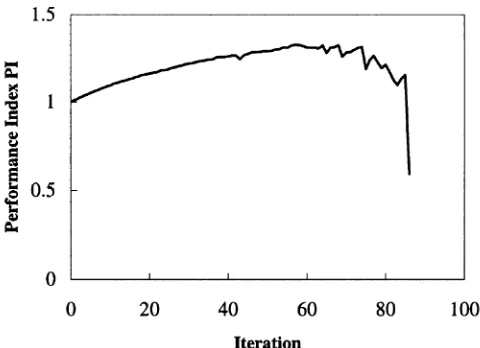
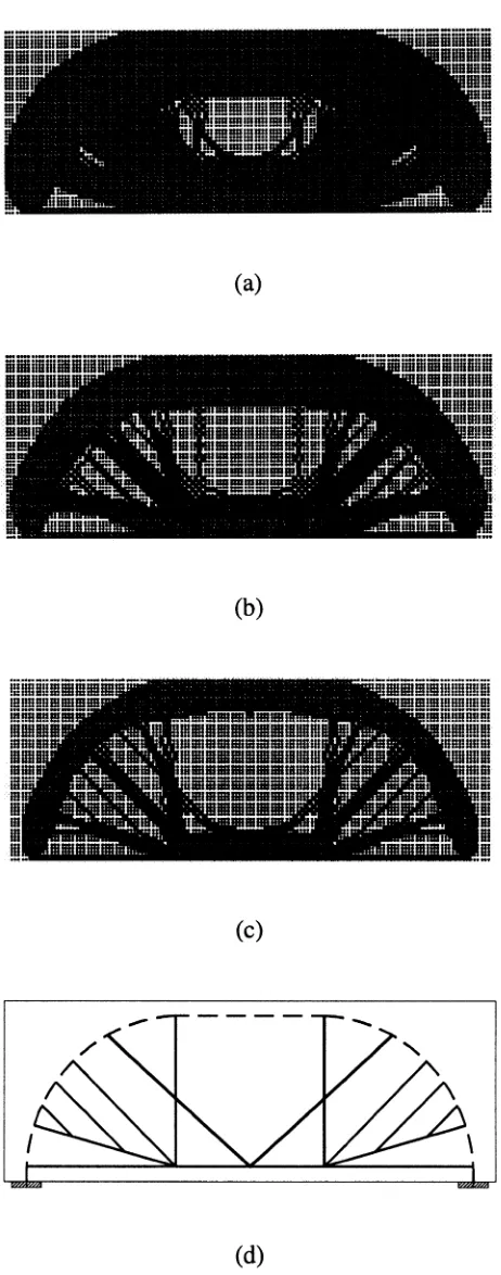
four-node plane stress elements. Two displacement constraints of the same limit are imposed on the two loaded points in the vertical direction. The ERR = 1% is adopted in the optimization process. The performance index history of the deep beam loaded at the bottom is presented in Fig. 2. While elements are systematically removed from the deep beam, the performance index is gradually increased from unity to the maximum value of 1.32, which corre-sponds to the optimal topology of the strut-and-tie model within the concrete member. The topologies obtained at different itera-tions for this deep beam are given in Fig. 3. It can be observed from Fig. 3 that when elements having the least contribution to the structural stiffness are removed from the member, the actual load transfer mechanism in the concrete member becomes clear, as characterized by the remaining elements.
The optimal topology shown in Fig. 3(c) indicates the best layout of the strut-and-tie model, in which the compressive arch is formed, and the rest of the members are in tension. The strut-and-tensile ties can be accurately located according to this opti-mal topology. The optiopti-mal topology shown in Fig. 3(c) is ideal-ized as the strut-and-tie model shown in Fig. 3(d), which can be used to determine the internal forces of the truss and reinforce-ment arrangereinforce-ments in the detail design. The vertical and in-clined reinforcements should be provided to transfer the loads to the compressive concrete arch. The dimension of the strut, ties, and nodes should be undertaken according to codes of practice, and is not discussed herein.
EXAMPLE 2
A simply supported deep beam with two web openings based on the test specimen (O-O.3/3) presented by Kong and Sharp28 is illustrated in Fig. 4. Two concentrated loads of P1 = 140 kN are applied to the top of the deep beam. The compressive cylinder strength of concrete fc′ = 35.5 MPa; Young’s modulus of concrete E = 30088 MPa; Poisson’s ratio ν = 0.15; and the width of the beam b = 100 are used in the analysis. The concrete beam is dis-cretized into 25 mm square four-node plane stress elements. The displacement constraints of the same limit are imposed on the two loaded points in the vertical direction to obtain the optimal strut-and-tie model with minimum deflections. The ERR = 1% is adopted in the optimization process.
[image:5.612.322.562.34.208.2] [image:5.612.59.296.34.148.2]Figure 5 shows the performance index history of the deep beam with web openings obtained by using the present proce-dure. The maximum performance index is 1.58, which indicates that the resulting design represents the optimal topology of the strut-and-tie model within the deep beam. The evolutionary to-pology optimization history is shown in Fig. 6(a) to (c), from which it can be observed that the load transfer mechanism with-in the concrete deep beam are gradually manifested by the re-maining elements. Ideally, the loads are transmitted along the Fig. 1—Deep beam loaded at bottom.
bot-327
shortest natural load paths between the loading and reaction points. If the opening intercepts the natural load path, the load is to be rerouted around the opening.9 This is confirmed by the op-timal strut-and-tie model shown in Fig. 6(d), which indicates that the loads are transmitted to the supports by the upper and lower struts around the opening. The presence of two inclined tensile ties that connect the upper and lower struts around the
opening in Fig. 6(d) is supported by the experimental observa-tions conducted by Kong and Sharp.28
EXAMPLE 3
The best strut-and-tie model is needed to be found for a sim-ply supported deep beam under the factored load P = 3000 kN with a large hole, as shown in Fig. 7. This concrete deep beam is based on the example given by Schlaich et al.2 The compres-sive design strength of concrete fc = 17 MPa; Young’s modulus
of concrete E = 20820 MPa; Poisson’s ratio ν = 0.15; and the initial width of the beam b0 = 400 mm are used in this study. The concrete beam is modeled using 100 mm square four-node plane stress elements. A displacement constraint is imposed on the loaded point in the vertical direction, and the ERR = 1% is adopted in the optimization process.
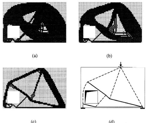
[image:6.612.66.297.26.613.2]Figure 8 demonstrates the performance index history of the deep beam with a large hole. After reaching the peak value, the performance index may drop sharply. This is because further el-ement removal will cause large deflections. The maximum per-formance index is obtained as 1.65, which corresponds to the optimal topology given in Fig. 9(c). The topologies obtained at different iterations in the optimization process are shown in Fig. 9. It is seen that the load is to be rerouted around the opening, even if the opening is very close to the support. The inclined ten-sile tie is developed across the upper right corner of the opening, which tends to crack under the applied load. The optimal strut-and-tie model obtained by the present study, as shown in Fig. Fig. 3—Optimization history of strut-and-tie-model in deep
beam loaded at bottom: (a) topology at iteration 20; (b) topol-ogy at iteration 40; (c) optimal topoltopol-ogy; and (d) optimal strut-and-tie model (Note: - - - = compressive strut; and —— =
[image:6.612.324.563.40.226.2]ten-Fig. 4—Deep beam with web openings.
[image:6.612.322.561.256.435.2]ACI Structural Journal/March-April 2000 328 9(d), is similar to the strut-and-tie model given by Schlaich et
al.2
EXAMPLE 4
This example is to investigate the effect of span-depth ratios on optimal strut-and-tie models in simply supported concrete beams under a concentrated load at the midspan of the beams, as shown in Fig. 10. The depth of the beams D is 1000 mm for all cases, while the span-depth ratio for Cases (a) to (d) is 2, 3, 4, and 5. The applied point load P = 1200 kN, and the initial width of the beam b0 = 250 mm are assumed for all cases. It is noted that the optimal topology of a linear elastic continuum structure under the plane stress condition does not depend on the scale of the point load and the width of the member. This can be seen from Eq. (12). The value of the loading, however, affects the fi-nal dimensions of struts and ties. The width of the beams can be changed to satisfy strength and stiffness requirements when di-mensioning the truss models. The compressive cylinder strength of concrete fc′ = 32 MPa; Young’s modulus of concrete E =
28567 MPa; and Poisson’s ratio ν = 0.15 are used for all cases. The concrete beams are modeled using 50 mm square four-node
plane stress elements, and the element removal ratio ERR = 1% is employed for all cases.
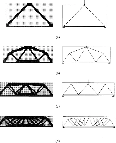
[image:7.612.320.562.32.209.2]The maximum performance indexes obtained for Cases (a) to (d) are 1.88, 1.3, 1.23, and 1.21, respectively. The optimal topol-ogy and corresponding strut-and-tie idealization for each case are presented in Fig. 11. It can be observed from Fig. 11 that the truss model that ideally represents the load transfer mechanism is changed from deep beams to slender beams. For beams with a span-depth ratio L/D ≥ 3, inclined tensile ties connecting the compressive concrete struts are necessary to form the truss mod-el, as shown in Fig. 11(b) to (d). For very slender concrete beams, optimal topologies obtained by the continuum topology optimization method are continuum-like structures, in which strut-and-tie actions are difficult to be identified, such as that shown in Fig. 11(d). For such cases, the flexural beam theory may be applied. These optimal strut-and-tie models indicate that the angles between compressive concrete struts and longitudinal ties are equal to or larger than 45 degrees. In detail design, some of the bottom steel bars may be bent up to resist the inclined ten-sile stresses or the shear in the shear spans.
Fig. 6—Optimization history of strut-and-tie model in deep beam with web openings: (a) topology at iteration 20; (b) topology at iteration 40; (c) optimal topology; and (d) optimal
[image:7.612.61.300.34.252.2]Fig. 7—Deep beam with large hole.
Fig. 8—Performance index history of deep beam with large
[image:7.612.321.564.254.459.2] [image:7.612.60.299.305.489.2]strut-and-329
EXAMPLE 5
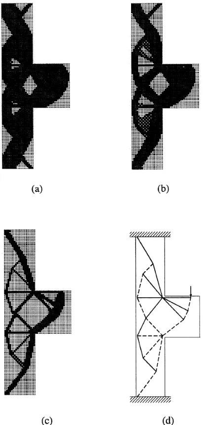
In this example, the corbel and column are considered as a whole structure that is designed to support a point load of 500 kN, as il-lustrated in Fig. 12. The column is fixed at both ends. The com-pressive cylinder strength of concrete fc′ = 32 MPa; Young’s modulus of concrete E = 28567 MPa; Poisson’s ratio ν = 0.15; and the width of the corbel and column b = 300 mm are assumed. This structure is modeled using 25 mm square four-node plane stress el-ements. A displacement constraint is imposed on the loaded point in the vertical direction, and the element removal ratio ERR = 1% is used in the optimization process.
Figure 13 shows the performance index history of the struc-ture. The maximum performance index is 1.34, and the corre-sponding optimal strut-and-tie topology is shown in Fig. 14(c). It can be observed from Fig. 14 that the applied load is trans-ferred to the whole range of the structure along the paths of compressive struts and tensile ties. This example shows that the column and corbel should be treated as a whole structure in de-veloping the best strut-and-tie model. The optimal strut-and-tie model illustrated in Fig. 14(d) is supported by the solution ob-tained by the load path method.2
DISCUSSIONS
Various examples given herein have shown that optimal strut-and-tie models in concrete members can be generated by using the proposed procedure. Although the present model considers the elastic behavior of cracked structural concrete, it provides a clear understanding of the nature of the load transfer mechanism in reinforced concrete members. Moreover, the results obtained by the present study confirm the findings of other researchers, and are supported by experimental evidence. It should be noted that there are no absolute optimal solutions. The objective of shape finding is principally used as a vehicle to get a better de-sign in terms of overall structural performance, and to free con-crete designers from the time-consuming development of truss models using conventional methods.
[image:8.612.365.507.34.308.2] [image:8.612.60.299.36.144.2]As mentioned previously, the load transfer mechanism in a re-inforced concrete member depends on its geometry, loading, and support condition. Without modification, the strut-and-tie mod-el devmod-eloped for a specific reinforced concrete member cannot be Fig. 10—Simply supported beams with various span-depth
[image:8.612.66.298.186.471.2]Fig. 11—Optimal topologies and truss models showing transition from deep beams to slender beams: (a) L/D = 2; (b) L/D = 3; (c) L/D = 4; and (d) L/D = 5.
Fig. 12—Corbel jointed with column.
[image:8.612.322.561.346.523.2]ACI Structural Journal/March-April 2000 330 used for different members. The initial size of a reinforced
con-crete member should be estimated based on the serviceability re-quirement. The proposed stiffness-based method produces the optimal topology, which indicates only the locations of struts, ties, and nodes of a strut-and-tie model in a structural concrete member. Dimensioning the struts, ties, and nodes is left to the designer. Since the width of a concrete member does not affect the optimal topology, it can be adjusted to satisfy strength and stiffness requirements when dimensioning the truss model ob-tained. It is common for continuum topology optimization methods that the mesh size has a considerable effect on the re-sult. The member geometry and computational time need to be considered in choosing the mesh size. Since an optimal topolo-gy obtained is still a continuum structure, the strut-and-tie ide-alization based on the continuum topology may have redundant members. It is suggested that the layout arrangement of steel re-inforcement should follow the optimal strut-and-tie model as closely as possible.
Conventional drawing board methods are especially not effi-cient in developing optimal strut-and-tie models in concrete members under multiple load cases because it is difficult to su-perpose different models for different load cases. The present computer-based topology optimization procedure, however, can easily deal with multiple loading conditions, and it is not limited to single and symmetry loading, although examples presented herein consider only one load case. The proposed design opti-mization procedure can also be applied to finding optimal strut-and-tie models in prestressed concrete structures and reinforced concrete shearwalls.
FURTHER RESEARCH
Further theoretical research should be focused on studying the effect of material property on the optimal strut-and-tie mod-els and minimizing the effects of element mesh size and remov-al ratios on the results. Experimentremov-al work is remov-also needed to investigate the ultimate load capacity of reinforced concrete members that are designed using optimal strut-and-tie models generated by the present topology optimization technique. Test results will be compared with current codes of practice.
CONCLUSIONS
A performance-based evolutionary topology optimization method for automatically developing optimal strut-and-tie mod-els in reinforced concrete structures has been presented in this paper. Five examples that cover various types of reinforced con-crete members have been provided to illustrate the effectiveness of the proposed optimization procedure. It has been shown that strut-and-tie models generated by the present optimization pro-cedure are supported by existing analytical solutions and exper-imental observations. The method can also be applied to finding optimal strut-and-tie models in prestressed concrete structures and reinforced concrete shearwalls. Further theoretical and ex-perimental work is needed to make topology optimization an in-tegrated and friendly routine design tool for concrete designers. Based on the present study, the following conclusions are drawn: 1. The proposed method in this paper is most appropriately used for finding optimal strut-and-tie models in nonflexural concrete members and in slender beams with L/D ≤ 5;
2. For very slender concrete beams, the optimal topologies obtained by the topology optimization method are continuum-like structures in which strut-and-tie actions are difficult to be identified;
3. The present study shows that for a deep beam loaded at the bottom, the vertical and inclined reinforcement should be pro-vided to transfer the loads to the compressive arch with suffi-cient anchorage, but not necessarily to the top of the deep beam, depending on the span-depth ratio of the beam;
4. When openings intercept the natural load paths, the load is to be rerouted around the openings where inclined tensile ties join the upper and lower struts. It is important to provide in-clined reinforcement at the top and bottom of the opening. This inclined reinforcement is efficient for crack control and for in-creasing the ultimate load capacity of the deep beam;
5. For reinforced concrete beams with L/D ≥ 3, inclined rein-forcements bent up from bottom steel bars are most efficient in resisting shear in the shear spans; and
6. In the structural idealization of corbels, the column that joins the corbel should be considered together with the corbel in developing the strut-and-tie model.
ACKNOWLEDGMENTS
[image:9.612.340.547.37.468.2]This paper forms part of a research program into the evolutionary struc-tural optimization as an efficient and reliable design tool. This program was funded by the Australian Research Council under the Large Grants Scheme. The first author is supported by an Australian Postgraduate Award and a Faculty of Engineering and Science Scholarship. The first author wishes to acknowledge helpful discussions with Prof. Lewis C. Schmidt in the Depart-ment of Civil, Mining, and EnvironDepart-mental Engineering at the University of Wollongong, Australia.
331 ACI Structural Journal/March-April 2000
CONVERSION FACTORS
1 mm = 0.039 in. 1 kN = 0.2248 kips 1 MPa = 145 psi
NOTATIONS
b = width of member
b0 = initial width of beam
D = depth of beam
E = Young’s modulus of concrete {Fj} = virtual unit load vector
fc = compressive design strength of concrete
fc′ = compressive cylinder strength of concrete [K ] = stiffness matrix of structure
[Kr] = stiffness matrix of resulting structure
[ke] = stiffness matrix of e th element
L = span of beam
m = total number of displacement constraints
n = total number of elements [P] = load vector
PI = performance index
te = thickness of e th element
u0 j = j th constrained displacement most critical in initial design
uij = j th constrained displacement most critical in current design
uj = absolute value of j th constrained displacement
uj* = prescribed limit of uj {u} = nodal displacement vector
{ue} = displacement vector of eth element under real loads {uej} = displacement vector of eth element under virtual unit load
{uj} = displacement vector of structure under virtual unit load
W = total weight of structure
W0 = actual weight of initial design
W0s = scaled weight of initial design
Wi = actual weight of current design at ith iteration
we = weight of e th element
αe = virtual strain energy of eth element
[∆K] = change of stiffness due to element removal {∆u} = change of displacement vector
λj = weighting parameter
ν = Poisson’s ratio
REFERENCES
1. Marti, P., “Basic Tools of Reinforced Concrete Beam Design,” ACI
Structural Journal , V. 82, No. 1, Jan.-Feb. 1985, pp. 46-56.
2. Schlaich, J.; Schäfer, K.; and Jennewein, M., “Toward a Consistent Design of Structural Concrete,” PCI Journal , V. 32, No. 3, May-June 1987, pp. 74-150.
3. ASCE-ACI Committee 445, “Recent Approaches to Shear Design of Structural Concrete,” Journal of Structural Engineering, V. 124, No. 12, Dec. 1998, pp. 1375-1417.
4. Ritter, W., “Die Bauweise Hennebique,” Schweizerische Bauzeitung, V. 33, No. 7, Zürich, Feb. 1899, pp. 59-61.
5. Mörsch, E., Der Eisenbetonbau-Seine Theorie und Anwendung
(Rein-forced Concrete Construction—Theory and Application ), 5th Edition,
Wit-twer, Stuttgart, V. 1, Part 1, 1920, Part 2, 1922.
6. Schlaich, J., and Schäfer, K., “Design and Detailing of Structural Con-crete Using Strut-and-Tie Models,” The Structural Engineer, V. 69, No. 6, 1991, pp. 113-125.
7. Rozvany, G. I. N.; Bendsøe, M. P.; and Kirsch, U., “Layout
Optimiza-tion of Structures,” Applied Mechanical Review, V. 48, No. 2, Feb. 1995, pp. 41-119.
8. Topping, B. H. V., “Topology Design of Discrete Structures,”
Topol-ogy Design of Structures, M. P. Bendsøe and C. A. Mota Soares, eds.,
Klu-wer Academic Publishers, 1993, pp. 517-534.
9. Kumar, P., “Optimal Force Transmission in Reinforced Concrete Deep Beams,” Computers & Structures, V. 8, No. 2, 1978, pp. 223-229.
10. Biondini, F.; Bontempi, F.; and Malerba, P. G., “Optimization of Strut-and-Tie Models in Reinforced Concrete Structures,” Proceedings of
the Australasian Conference on Structural Optimization, Sydney, G. P.
Steven; O. M. Querin; H. Guan; and Y. M. Xie, eds., Oxbridge Press, 1998, pp. 115-122.
11. Dorn, W. S.; Gomory, R. E.; and Greenberg, H. J., “Automatic Design of Optimal Structures,” Journal de Mecanique, V. 3, Mar. 1964, France.
12. Bendsøe, M. P., and Kikuchi, N., “Generating Optimal Topologies in Structural Design Using a Homogenization Method,” Computer Methods
in Applied Mechanical Engeneering, V. 71, 1988, pp. 197-224.
13. Zhou, M., and Rozvany, G. I. N., “The COC Algorithm, Part II: Topological, Geometrical and Generalized Shape Optimization,” Computer
Methods in Applied Mechanical Engeneering, V. 89, 1991, pp. 309-336.
14. Rozvany, G. I. N.; Zhou, M.; and Birker, T., “Generalized Shape Optimization without Homogenization,” Structural Optimization, V. 4, 1992, pp. 250-252.
15. Xie, Y. M., and Steven, G. P., “A Simple Evolutionary Procedure for Structural Optimization,” Computers & Structures , V. 49, No. 5, 1993, pp. 885-896.
16. Xie, Y. M., and Steven, G. P., “Evolutionary Structural Optimization for Dynamic Problems,” Computers & Structures , V. 58, 1996, pp. 1067-1073.
17. Xie, Y. M., and Steven, G. P., Evolutionary Structural Optimization, Springer-Verlag, Berlin, 1997.
18. Chu, D. N.; Xie, Y. M.; Hira, A.; and Steven, G. P., “Evolutionary Structural Optimization for Problems with Stiffness Constraints,” Finite
Elements in Analysis and Design, V. 21, 1996, pp. 239-251.
19. Liang, Q. Q.; Xie, Y. M.; and Steven, G. P., “Optimal Selection of Topologies for Minimum-Weight Design of Continuum Structures with Stress Constraints,” Proceedings of the Institution of Mechanical
Engi-neers, Part C, Journal of Mechanical Engineering Science, V. 213, No. C8,
1999, pp. 755-762.
20. Liang, Q. Q.; Xie, Y. M.; and Steven, G. P., “Optimal Topology Selection of Continuum Structures with Displacement Constraints,”
Com-puters & Structures, 1999. (submitted for publication)
21. Liang, Q. Q.; Xie, Y. M.; and Steven, G. P., “A Performance Index for Topology and Shape Optimization of Plate Bending Problems with Displace-ment Constraints,” Structural Optimization, 1999. (accepted for publication)
22. Cohn, M. Z., and Dinovitzer, A. S., “Application of Structural Optimization,” Journal of Structural Engineering, V. 120, No. 2, Feb. 1994, pp. 617-649.
23. Hemp, W. S., Optimum Structures, Clarendon Press, Oxford, 1973. 24. Kirsch, U., “Optimal Design Based on Approximate Scaling,”
Jour-nal of Structural Engineering, V. 108, No. ST4, 1982, pp. 888-909.
25. Morris, A. J., ed., Foundations of Structural Optimization: A Unified
Approach, John Wiley & Sons, New York, 1982.
26. AS 3600, Concrete Structures, Standards Association of Australia, Sydney, 1994.
27. Marti, P., “A Simple, Consistent Approach to Structural Concrete,”
The Structural Engineer, V. 77, No. 9, May 1999, pp. 20-26.