This is a repository copy of Computational Design and Optimisation of Pin Fin Heat Sinks
with Rectangular Perforations.
White Rose Research Online URL for this paper:
http://eprints.whiterose.ac.uk/96442/
Version: Accepted Version
Article:
Al-Damook, A, Kapur, N orcid.org/0000-0001-8266-5038, Summers, JL et al. (1 more
author) (2016) Computational Design and Optimisation of Pin Fin Heat Sinks with
Rectangular Perforations. Applied Thermal Engineering, 105. pp. 691-703. ISSN
1359-4311
https://doi.org/10.1016/j.applthermaleng.2016.03.070
© 2016, Elsevier. Licensed under the Creative Commons
Attribution-NonCommercial-NoDerivatives 4.0 International
http://creativecommons.org/licenses/by-nc-nd/4.0/
[email protected] https://eprints.whiterose.ac.uk/
Reuse
Unless indicated otherwise, fulltext items are protected by copyright with all rights reserved. The copyright exception in section 29 of the Copyright, Designs and Patents Act 1988 allows the making of a single copy solely for the purpose of non-commercial research or private study within the limits of fair dealing. The publisher or other rights-holder may allow further reproduction and re-use of this version - refer to the White Rose Research Online record for this item. Where records identify the publisher as the copyright holder, users can verify any specific terms of use on the publisher’s website.
Takedown
If you consider content in White Rose Research Online to be in breach of UK law, please notify us by
1
Computational Design and Optimisation of Pin Fin Heat Sinks with Rectangular PerforationsAmer Al-Damook, J.L. Summers, N. Kapur, H.M. Thompson
School of Mechanical Engineering, University of Leeds, UK
Accepted for publication: 13th March 2016
ABSTRACT
The benefits of using pin heat sinks (PHSs), where the pins are perforated with single, rectangular slotted
or notched perforations, are explored computationally, using a conjugate heat transfer model for the
conductive heat transfer through the heat sink and into the turbulent air flow over the heat sink. Results
show that the heat transfer increases monotonically while the pressure drop decreases monotonically as
the size of the rectangular perforation increases. Performance comparisons with PHSs with multiple
circular perforations show that reduced manufacturing complexity of rectangular notched pins in
particular, together with their favourable heat transfer and pressure drop characteristics, provide strong
motivation for their use in practical applications. Detailed parameterisation and optimisation studies into
the benefits of single rectangular notch perforations demonstrate the scope for improving heat transfer and
reducing mechanical fan power consumption yet further by careful design of pin density and pin
perforations in PHSs for specific applications.
NOMENCLATURE
Reynolds number Re
cross-sectional area of the flow passage of the heat sink, m2
A
ctemperature, oC T
pin diameter of the pin fin heat sink, mm
D
temperature difference, oC ∆T
hydraulic diameter, m h
D
air velocity, m/s U
pin fin height, mm H
Greek
heat transfer coefficient, W/m2.K h
fluid thermal diffusivity (m2/s) turbulence kinetic energy, m2s-2
k
turbulence model constant , , *
number of perforations n
porosity Vvoid=V number of pins
N
fluid viscosity (Pa·s) heat sink length, mm
L
turbulent eddy viscosity, Pa.s t
Nusselt number Nu
fluid density (kg/m3) fan power, W
fan P
kinematic viscosity, m2/s t
pressure drop, Pa ∆p
turbulent kinematic viscosity, m2/s
t Prandtl number
Pr
k- turbulence model constant turbulent Prandtl number
t Pr
turbulence model constant for the k-equation power applied on the base, W
Q
k- turbulence model constant pin pitch in streamwise direction, mm
Sz
INTRODUCTION
The increasing focus on energy efficiency and environmental sustainability, together with the need to
achieve higher cooling rates, are providing strong drivers to optimise the performance of cooling
technologies for a range of critical applications in e.g. the aerospace, avionics, automotive and nuclear
industries, Sahin & Demir (2008,15). The electronics industry is also facing formidable challenges due to
inexorable increases in power densities which make it increasingly difficult to ensure that
micro-electronics temperatures remain below critical values above which failure modes associated with metal
migration, void formation and inter-metallic growth degrade reliability, Gurrum et al (2004,17). These are
driving rapid innovations in the thermal management of electronics towards promising technologies which
include the use of highly conductive inserts to provide efficient pathways for heat removal,
2
well as greater use of formal optimisation methods for component design, Najafi et al (2011, 19).Promising liquid cooling methods include on-chip cooling currently being used in the Aquasar system (1),
which brings coolant right up to the main processor, and dielectric liquid immersion which removes heat
by natural convection currents, Hopton & Summers (2013,2).
Cooling by convective heat transfer to air as it flows over a network of extended surface fins on a heat
sink is still currently the most common cooling approach for microelectronics due to its low cost,
availability and reliability, Zhou & Catton (2011,3). The fins offer a practical means of achieving a large
total heat transfer surface area without excessive primary surface area and act as turbulence promoters
thus further enhancing heat transfer rates. These heat sinks are usually designed to provide sufficient heat
transfer rates to ensure that processor temperatures remain below the critical values, for minimal pressure
loss, see e.g. the recent review by Nagarini et al (2014). The most widely used heat sink designs are those
based on rectangular plate fin heat sinks (PFHSs) due to their simple structure and ease of manufacturing.
These have been widely studied in the scientific literature and several studies have used experimental,
Chiang (2005,5), and numerical, Najafi et al (2011,19), methods in order to improve heat transfer rates by
limiting the regions where air flows smoothly through the heat sink channels. Recent attempts to overcome
the latter include those of Kotcioglu et al (2013,20), who used periodically interrupted diverging and
converging fins to enhance heat transfer through boundary layer disturbances and secondary mixing, and
Kumar Das & Ghosh (2012) who considered the benefits of using multiple air streams to disturb the
boundary layer. Najafi et al (2011,19) have used multi-objective Genetic Algorithms to optimise plate fin
geometries for total heat transfer rate and annual costs.
Recent experimental and numerical studies have shown that perforating PFHSs can also offer substantial
improvements in heat transfer with reduced pressure losses. The experiments of Dhanawade and
Dhanawade (2010,14), for example, studied the effect of circular perforations parallel to the dominant air
flow direction and found that perforations lead to reductions in the pressure loss by reducing both the size
of the wakes behind the fin and the length of the recirculation zone around the lateral surfaces of the fins.
These also showed that perforations generally increase the rate of heat transfer and that the optimum
perforation diameter is a function of the applied heat flux density, with larger perforations being beneficial
for low heat fluxes and smaller perforations better for high heat fluxes. Shaeri & Yaghoubi (2009,8,9)
used numerical methods to study thermal air flows over arrays of solid and perforated plate fins, where
the latter are perforated with one of more rectangular channels parallel to the dominant flow direction.
They also found substantial improvements in heat transfer rate and reductions in total drag when
perforations were used and noted that these benefits can be achieved with substantial reductions in fin
weight, of up to 50%, for the cases considered.
Replacing plate fins by pins on Pinned Heat Sinks (PHSs) can be an effective enhancement to PFHSs
since the pins hinder the development of the thermal boundary layer on smooth surfaces that limits the
heat transfer rates in PFHSs, Zhou & Catton (2011). Previous investigations of heat transfer and pressure
drops for air flows over PHSs have demonstrated clearly their superiority over PFHSs, Soodphakdee
(2011). Attempts to further improve their performance have carried out design optimisation by exploring,
for example, the effect of pin cross-sectional shape, Jonson & Moshfeghar (2001) and the benefits of
3
In comparison with PFHSs, relatively few studies have considered the effect of perforations on heattransfer and pressure drops in PHSs and these have mainly focussed on the benefits of single perforations.
Sahin & Demir (2008,15,16), for example, studied the effect of cross-sectional shape (circular or square)
for in-line pin arrays while Amol et al (2013,17) considered the effect of staggered pin arrangements for
singly-perforated pins of circular cross-section. More recently, Dai et al (2013) studied the benefits of
micro-jets to improve heat transfer rate and reduce pressure drop by inducing flow separation in PHSs.
Collectively, these studies have shown that, compared to solid pin systems, localised jet flows through
perforations increase local heat transfer by increasing shear-induced mixing and, in addition, reduce
overall pressure drop by reducing the size and strength of the recirculating zones that form behind the
pins.
Al-Damook et al (2015,18) have very recently used complementary experimental and numerical methods
to explore the benefits of using multiple pin perforations within PHSs for the first time. They showed that
the heat transfer rate increases monotonically with the number of pin perforations, while the pressure drop
and fan power, required to overcome the pressure drop, both reduce monotonically; the location of the
perforations were found to be much less influential. Pins with five perforations were found to increase
heat transfer rate by over 10%, and reduce pressure drop by over 15%, compared with corresponding solid
pin cases. These benefits are due not only to the increased surface area but also caused by the interactions
of localised air jets through the perforations. Their conjugate heat transfer analysis showed, further, that
improved heat transfer with pin perforations leads to significantly reduced processor case temperatures
with the additional benefit of a reduction in the weight of the pins. Their experiments also revealed that
practical considerations, including pin perforation alignment with the dominant flow direction and the quality of the pins’ surface finish, can affect the heat transfer and pressure drop significantly.
The present study extends the recent work of Shaeri & Yaghoubi (2009,8,9) and Al-Damouk et al
(2015,18) to consider the benefits of using pins with both internal rectangular perforations and with
rectangular perforations etched into the top of the pins, see Figure 1. Since the latter may perhaps offer a
more practical means of manufacturing PHSs with perforated pins, a multi-objective optimisation of the
heat transfer and pressure drop in such systems is also presented. The paper is organised as follows.
Section 2 describes the conjugate heat transfer model for the PHS problems under consideration and the
numerical methods used to solve them. A comprehensive set of solutions is presented in Section 3 and
conclusions are drawn in Section 4.
2. NUMERICAL METHODS
2.1 Problem Description
The PHS configurations considered here are shown in Figures 1 and 2 and based on those considered
in the recent experimental study by Al-Damouk et al (2015), having base dimensions 50mm x 50mm x
2mm with an array of equally spaced 2mm diameter and 10mm height pins of circular cross-section.
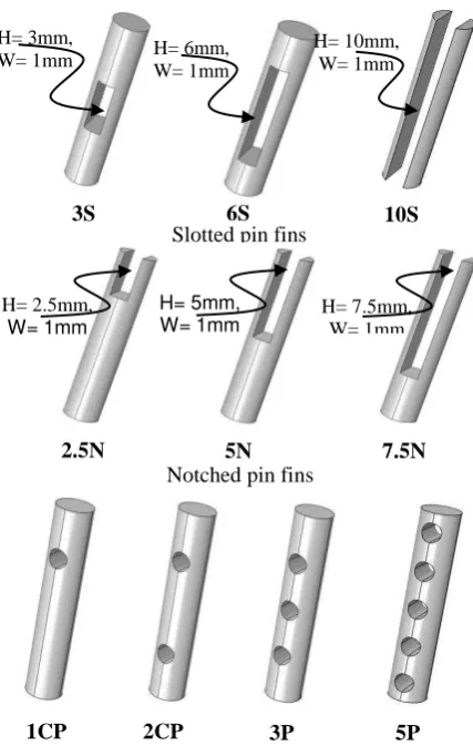
Thermal airflows past PHSs with pins based on three pins designs with rectangular perforations (henceforth referred to as ‘slotted’ pins) and three with rectangular notches removed from the top of the pin (‘notched’ pins) are compared with baseline cases with solid pins and pins with circular perforations considered by Al-Damouk et al (2015). The slotted pin designs have slot heights 3mm (3S), 6mm (6S)
4
constant slot and notch width of 1mm. The porosities of the pin fins, defined as =Vhole/V where Vhole, and V are the volume of the perforations and total pin volume respectively, range between 0 and 0.62.2.2 Conjugate Heat Transfer Model
Thermal airflow through an aluminium PHS is analysed using Computational Fluid Dynamics (CFD). A
schematic diagram of the flow domain used in the CFD analyses, with eight perforated pins in the air flow
direction, is given in Figure 3 and consists of an inlet section, a test section over the PHS and an outlet
section. The inlet air temperature is set to 25oC and the inlet air velocity is varied between 6.5m/s and 12m/s leading to Reynolds numbers in the range 3500-6580 based on a length scale given by the hydraulic
diameter of the duct Dh=2H.B/(H+B), where H and B are height and width of duct in which the heat sink is located, respectively.
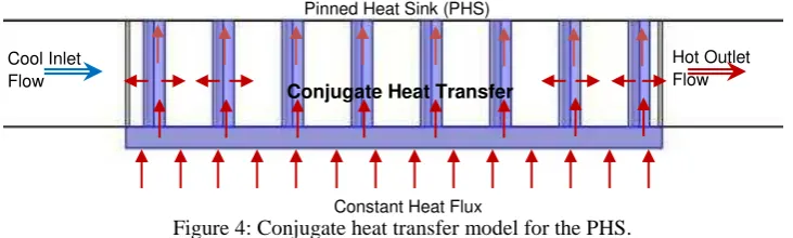
The rate of heat conduction through the aluminium heat sink is balanced by heat transfer by convection
into the moving air stream, through a coupled boundary condition at the solid/fluid interface, as illustrated
in Figure 4.
Slotted pin fins
H= 3mm,
W= 1mm H= 6mm,
W= 1mm
H= 10mm, W= 1mm
3S 6S 10S
2.5N H= 2.5mm,
W= 1mm
H= 5mm,
W= 1mm H= 7.5mm, W= 1mm
Notched pin fins
[image:5.595.92.306.316.653.2]5N 7.5N
Figure 2: Plan view and side view of the PHSs being analysed.
1CP 2CP 3P 5P
Figure 1: Slot (S) and notch (N) perforations considered, together with circular (P) perforations
considered by Al-Damouk et al (2015).
Inlet
Outlet
Heat Sink Pin Fins
L
H
Constant Heat Flux Adiabatic walls
Adiabatic walls
Symmetry
5
In the solid heat sink the temperature field Ts is obtained by solving the steady heat conduction equation0
)
.(
k
sT
swhere ks=202W/mK is the thermal conductivity of the aluminium heat sink. Turbulent flow through the PHSs is modelled using Reynolds-Averaged Navier-Stokes (RANS) equations, Zhou & Catton (2011),
where the continuity, momentum and energy equations have variables decomposed into mean and
fluctuating components, leading to:
0
.
U
1 .
' '
.UU UU
t U
where
p
I
U
U
T
and
U
'
U
'
t
U
U
T
2
3
(
k
I
)
are theNewtonian and Reynolds Stress tensors respectively, is the air viscosity, its density, U and
U
'
theaverage and turbulent fluctuation velocity vectors respectively, p is the pressure and
I
the unit tensor.The incompressible RANS equations are solved with the energy equation for the temperature field in the
fluid, Tf, with a heat source Watts, using the following equation
p f t t f
f
C
Q
T
T
U
t
T
2Pr
Pr
.
where Cp is the specific heat capacity of the air, Pr and are the Prandtl number and kinematic viscosity of the air respectively and the subscript t indicates their turbulent counterparts.
Following Zhou & Catton [3], Leung & Probert [21] and Al-Damouk et al [18], the thermal airflow
through the heat sink is modelled using the k- SST model, which combines the accurate formulation of
the k- model in the near-wall region with the free-stream independence of the k- one in the far field.
Constant Heat Flux Cool Inlet
Flow
Conjugate Heat Transfer
[image:6.595.118.484.193.303.2]Hot Outlet Flow Pinned Heat Sink (PHS)
6
This has been shown to predict highly separated flows accurately in a number of previous validationstudies, Menter [22], Zhou & Catton [3]. These studies also showed that the effects of radiative heat
transfer can be neglected in flow over heat sinks and this simplifying assumption is also adopted here. Air
density and viscosity are assumed to be constant and equal to those at the inlet temperature of 25oC.
The equations for the SST model are:
k
k P k U t k t k
k
) ( . ~ ) ( . ) ( *
. 1 ) 1 ( 2 ) ( . ) ( . ) ( 2 1 22 F k
S U
t t
where the blending function F1 is defined by
4 2 2 * 1 2 4 , 500 , max min tanh y D C k y y k F k in which
10
10 , . 1 2 max
2
k
D
C k
The turbulent eddy viscosity is computed from
) , max( 1 2
1 F S a k a t
where S is the invariant measure of the strain rate and F2 is a second blending function defined by
2 2 * 2 500 , 2 max tanh
y y
k
F
[image:7.595.86.528.576.776.2]To limit the growth of turbulence in stagnation regions, a production limiter is used in the SST model.
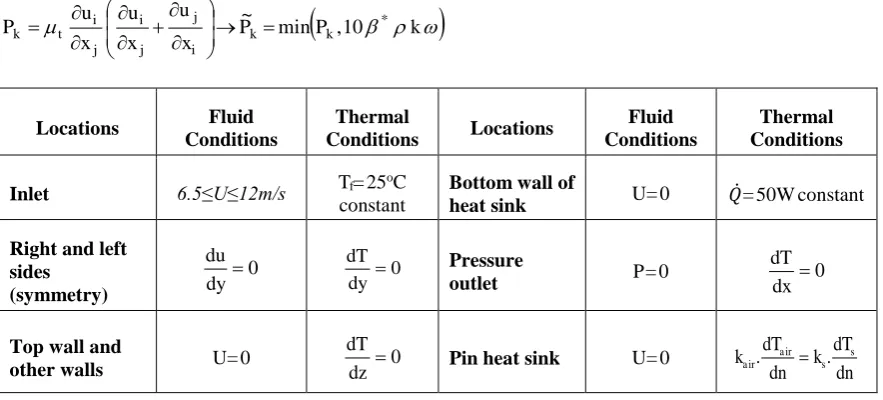
Table 1: The boundary conditions of the conjugate heat transfer model.
P P kx u x u x u
P k k
i j j i j i t
k min ,10 *
~
Locations Fluid
Conditions
Thermal
Conditions Locations
Fluid Conditions
Thermal Conditions
Inlet 6.5≤U≤12m/s Tf= 25
oC constant
Bottom wall of
heat sink U= 0 = 50W constant
Right and left sides (symmetry) 0 dy du 0 dy dT Pressure
outlet P= 0 dx0
dT
Top wall and
other walls U= 0 dz 0
dT
Pin heat sink U= 0
7
The constants for this model are: * 0.09, 1 59, 1 340, 1 0.85, 0.5, 2 0.44,1
k
. 856 . 0 ,
1 , 0828 .
0 2 2
2
k
A commercial Finite Volume Method-based code, ANSYS FLUENT [23] is used to solve the fully
coupled momentum and energy equations, using second order upwinding, while continuity is satisfied
using the SIMPLE method. The grid is composed of tetrahedral mesh elements to improve the quality of
the numerical prediction near curved pin surfaces.
Table 1: The boundary conditions of the conjugate heat transfer model.
2.3 Boundary Conditions
The computational problem is reduced in size by exploiting the symmetry of the PHS to apply symmetry
boundary conditions (Table 1) along the sides of the channel so that the conjugate heat transfer model is
solved for a system of equally spaced pins aligned with the dominant flow direction, Figure 3. Along the
bottom wall of the heat sink, a constant heat flux =50W is applied and no-slip conditions U=0 are
imposed along the heat sink walls. A pressure outflow boundary condition is imposed at the outlet
boundary. All remaining walls are considered to be adiabatic.
2.4 Post Processing
In addition to the thermal airflow throughout the PHSs, the CFD analysis is used to determine the Nusselt
number, Nu, pressure drop, p, mechanical fan power, Pfan, and CPU temperature, Tcase [32]. The average heat transfer coefficient, h, and Nusselt number, Nu, are defined by
,
where the area AS is based on either the projected base area, AP, or total wetted surface area, AT, of the heat sink which includes the pin and perforation surface areas, TW is the heat sink temperature at its upper surface, Tin and Tout are the average inlet and outlet air temperatures respectively.
The fan power required to drive the air through the heat sink, ignoring losses due to fan inefficiency, is
defined by [31]
Pfan= Uair.A. p
where Uair is the inlet air velocity and A is the cross-sectional area of the flow passage of the heat sink=H.Sz.(N-1), where Sz is the uniform pin spacing.
3. RESULTS AND DISCUSSION
3.1 Effect of Grid Density
Numerical solutions of the conjugate heat transfer model are obtained on a series of grids for both the
solid and perforated pin fin cases shown in Figure 1 and the effect of grid resolution on NuT, Tcaseand p are shown in the Appendix in Table A.1. For solid pin fins increasing the number of cells beyond 124,000
leads to a less than 3% variation in the quantities of interest, whereas for slotted and notched pin fins,
increasing the number of cells beyond 116,000 and 117,000, respectively results in less than 2% variation
in these parameters. All results reported subsequently have used these appropriate levels of grid refinement
8
3.2 Validation with Previous StudiesThe numerical approach used here has recently has been shown to agree well with previous experimental
and numerical studies of flows past PHSs with solid and circularly perforated pins, Al-Damouk et al
(2015). Figure 5 compares the present study’s predictions of the thermal resistance,
of a solid PHS with the experimental results of Jonsson & Moshfegh [25] and the
numerical data of Zhou & Catton [3] for 6.5m/s≤ Uin≤10m/s. The agreement is generally very good, with a maximum discrepancy between these studies less than 3%.
3.3 Effect on Pressure Drop and Fan Power Consumption in PHSs
Figures 6 and 7 show numerical predictions of the effect of slot and notch perforations on p and Pfan respectively. Data is presented for the six slot and notch perforations shown in Figure 1 and compared
against the benchmark PHS with solid pins. These show that both the slot and notch perforations reduce p and Pfan significantly and that the magnitude of these reductions increases monotonically with perforation size. For example, the 10S and 7.5N perforations lead to reductions in p and Pfan of approximately 40% and 35% respectively compared to solid pin PHSs.
0.9 0.95 1 1.05 1.1 1.15 1.2 1.25 1.3
6 7 8 9 10 11
U (m/s) Rth ( K /W )
Experimental Data of Jonsson & Moshfeg Model Zhou & Catto
[image:9.595.182.381.206.400.2]Present CFD Data
Figure 5: Comparison of thermal resistancepredictions with CFD results of Zhou & Catton [3], and experimental data of Jonsson &
[image:9.595.64.510.564.839.2]Moshfeg [25].
Figure 6: Effect of slotted (A) and notched (B) pins on pressure drop with variation airflow speed 20 30 40 50 60 70 80 90 100 110
6 7 8 9 10 11 12 13
∆p (Pa ) U (m/s) 3S 6S 10S 0P 20 30 40 50 60 70 80 90 100 110
6 7 8 9 10 11 12 13
∆P (Pa ) U (m/s) 2.5N 5N 7.5N 0P
(A) (B)
0.2 0.25 0.3 0.35 0.4 0.45 0.5 Fa n P ow e r (W ) 3S 6S 10S 0P 0.2 0.25 0.3 0.35 0.4 0.45 0.5 Fan Pow er ( W ) 2.5N 5N 7.5N 0P
9
3.4 Effect on Heat Transfer RateSince one of the main design goals for PHSs is to achieve a high heat transfer rate at the minimum energy
cost, Figure 8 shows the corresponding numerical predictions of Nusselt number, based on either the total
PHS wetted surface area, NuT, or on the projected surface area, NuP. The latter may be a more effective measure of a heat sink’s cooling capacity for a given PHS size. The data shows that both NuT and NuP increase approximately linearly with the Reynolds number and that NuT of the perforated pins is slightly smaller than for the solid pins. This contrasts with the values of NuP, which increase monotonically and strongly with perforation size. Since NuP is based on a constant projected area, these demonstrate that perforations improve the magnitude of the heat transfer and the magnitude of these increases is also
significant: the values of NuP for the 10S and 7.5N perforations are typically 15% and 13% larger respectively than for solid pin PHSs. However, the fact that the values of NuT have decreased slightly means that the increase is heat transfer is slightly proportionately less than the increase in the total wetted
surface area in the heat sink due to the perforations. These findings are consistent with the recent
conclusions of Sara et al [26].
250 270 290 310 330 350 370
3250 3750 4250 4750 5250 5750 6250 6750
Nu
T
Re 3S
6S
10S
0P
250 270 290 310 330 350 370
3250 3750 4250 4750 5250 5750 6250 6750
Nu
T
Re 2.5N
5N
7.5N
0P
(A) Slotted Pins (A) Notched Pins
900 1000 1100
Nu
P
3S
6S
10S
0P
900 1000 1100
Nu
P
2.5N
5N
7.5N
0P
10
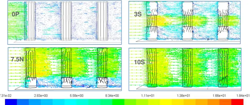
Collectively, Figures 6, 7 & 8 show that p and Pfan decrease monotonically and NuP increases monotonically with increasing perforation height, H.The nature of the flow field in the vicinity of the slotted and notched perforations influences the pressure
drop and heat transfer enhancements that they produce, Sara et al [26]. Figure 9 shows that the
recirculating flow region behind the solid pins (0P) is reduced considerably by the addition of the
perforations, which lead in turn to air jets flowing through them which enhance the local heat transfer rate
and reduce the pressure drop across them.
3.5 Thermal Management of PHSs and Pin Weight Reductions
In many electronics applications systems, PHSs provide the cooling needed to keep processor
temperatures below critical temperatures where thermally-driven failure mechanisms, including
intermetallic growth, corrosion, metal migration and void formation, degrade reliability and reduce the
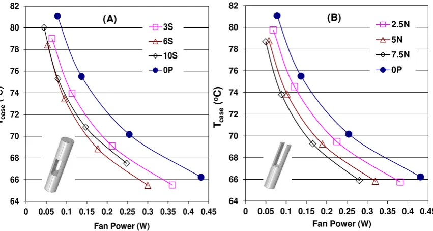
mean-time-to-failure [27, 28]. Figure 10 presents numerical predictions of the average PHS base plate
temperature, Tcase,as a function of the fan power needed to overcome the pressure drop, for inlet air velocities in the range 6.5m/s≤U≤12m/s. Both sets of data show the consistent trend of requiring higher
fan power in order to reduce Tcase and that the improved heat transfer from the slotted and notched pins leads to lower CPU temperatures compared to solid pins, for a specific fan power. With the exception of
0P 3S
[image:11.595.84.487.418.588.2]7.5N 10S
11
the 10S slot design, which differs in the sense that it effectively doubles the number of pins, Tcase decreases monotonically with perforation area, PHSs with the slotted 6S and notched 7.5N pins, for example,typically have Tcase values 4oC lower than for solid PHSs, for the same fan power input.
Since minimising the weight of consumer electronic devices is very important, previous studies have
considered the optimization of pin fins in terms of maximising the heat transfer rate for a given fin weight
or by minimising the weight for a specified heat transfer rate, Shaeri & Yagoubi [10]. The 3S, 6S and 10S
slotted pins reduce the weight of the pin by 20%, 35% and 60% respectively while the corresponding
reductions for the 2.5N, 5N and 7.5N notched pins are 15%, 30% and 45% respectively. Consequently,
the heat transfer, pressure drop and fan power benefits of the 7.5N notched pins also provide a further
benefit of a 45% reduction in pin weight.
Figure 11 compares the surface temperatures of the solid pin fin heat sinks with those obtained with the
6S and 7.5N pin fins. In the former case, temperatures on the base plate vary between approximately
58.5oC and 71oC, whereas for the slotted (6S) and notched (7.5N) pins models the corresponding temperatures vary between approximately 54.5oC-70oC, 55.5oC-70oC, respectively. The temperatures on the pins are also significantly cooler, as indicated by the greater preponderance of blue regions on the new
pin designs.
The effectiveness of the slotted and notched perforations can be compared further with the performance
benefits offered by the single and multiple circular perforations considered recently by Al-Damook et al
(2015). Table 3 compares typical percentage improvements in Nup, Pfan and Tcase produced by the perforations in Figure 1, compared to the case when only solid pins are used.
0P
7.5N 6S
[image:12.595.81.507.243.470.2]Figure 11: Temperature distribution through pinned heat sinks: 0P, 6S, and 7.5N models at Re=5393 Figure 10: Effect of slotted and notched pin perforations on Tcase as a function of input fan power 64
66 68 70 72 74 76 78 80 82
0 0.05 0.1 0.15 0.2 0.25 0.3 0.35 0.4 0.45
Tcase
(
oC)
Fan Power (W) 3S
6S
10S
0P
64 66 68 70 72 74 76 78 80 82
0 0.05 0.1 0.15 0.2 0.25 0.3 0.35 0.4 0.45
Tcase
(
oC)
Fan Power (W)
2.5N
5N
7.5N
0P
12
Table 3: Comparison in performance improvements for PHSs with pin designs shown in Figure 1.Pin design % increase in
AT
% increase in Nup
% reduction in Pfan
% reduction in Tcase
1CP 5% 7 3 2
2CP 10% 17 7 5
3CP 15% 24 9 8
5CP 25% 35 16 10
3S 10% 8 17 2
6S 15% 15 31 2
10S 20% 17 42 0
2.5N 5% 4 12 1
5N 10% 8 26 2
7.5N 15% 13 35 2
These show that there is a compromise to be struck between the choice of perforations since the larger
enhancements in heat transfer with multiple circular perforations come at the price of both a significantly
increased power consumption and, perhaps most importantly, a much more complex manufacturing
process. The above results suggest that PHSs with 7.5N notched pins may provide an effective, practical
means of obtaining a good combination of heat transfer efficiency with a relatively low fan power
consumption. All subsequent results focus on a parametric investigation of PHSs with notched pins.
3.6 Effect of heating rate
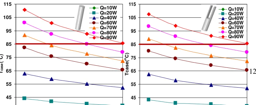
Since modern CPUs have dynamically changing voltages, leading to variations in heating power at the
base of a PHS, Figure 12 considers the effect of , on Tcase for a PHS with an 8x8 array of 7.5N notched pins. The heating power considered is in the range10W≤ ≤90W, typical of heating generated by PCs [28]. Taking 85oC as a critical T
case above which processor reliability degrades [27,28], Figure 12 shows that the critical temperature is exceeded for heating powers above 70W for air speeds below 8m/s, while
the air speed must be above 10m/s for a power of 80W and above 12m/s if the power is greater than 90W.
45 55 65 75 85 95 105 115
T
case
(
o C)
Q=10W Q=20W Q=40W Q=60W Q=70W Q=80W Q=90W
45 55 65 75 85 95 105 115
T
c
a
s
e
(
oC)
13
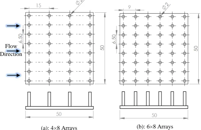
3.7 Effect of pin densityThe next series of results investigate the effect of varying the density of 7.5N notched pins on PHSs by
investigating cases where each column of pins has 8 equally spaced pins, but varying numbers of equally
spaced columns. Figures 13 (a) and (b) show two example PHSs with 4 and 6 columns of pins respectively.
Figure 14 shows the effect of the number of columns of pins on NuP for PHSs with both solid and 7.5N notched pins, for a range of Reynolds numbers. It shows that NuP for the notched pins are typically at least 10% larger than for the solid pins and the values of NuP typically double as the number of columns is varied between 4 and 11.
(b): 6×8 Arrays (a): 4×8 Arrays
[image:14.595.106.448.380.601.2]Flow Direction
[image:14.595.75.507.467.815.2]Figure 13: Schematic diagram of PHSs with different numbers of equally spaced columns: (a) 4 columns of 8 pins and (b) 6 columns of 8 pins.
Figure 14: Effect of the number of columns on Nu with variation Reynolds number for both solid 400
500 600 700 800 900 1000 1100 1200 1300
4 5 6 7 8 9 10 11
Nu
P
Number of columns Re=3500
Re=4315 Re=5393 Re=6580
Each Row has 8 Notched Pins (7.5N)
400 500 600 700 800 900 1000 1100 1200 1300
4 5 6 7 8 9 10 11
Nu
P
Number of columns
Re=3500 Re=4315 Re=5393 Re=6580
14
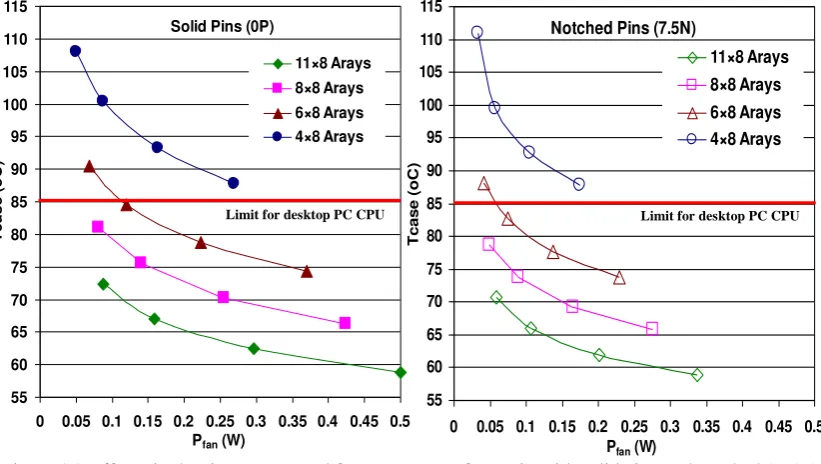
The effect of pin density on the CPU temperature and fan power are shown in Figure 15. Results areplotted with respect to a reference critical temperature of 85oC. The results show that the increased heat conduction from the CPU, resulting from the higher pin densities, means that the CPU can be cooled below
the critical temperature for a significantly lower fan power input, Pfan. For the solid pins, a fan power of 0.1W enables the CPU temperature Tcase to be maintained below 85oC when 6 columns of pins are used whereas for 4 columns the CPU temperature of 100oC is well above the critical value. Using columns of 7.5N notched pins reduces the CPU temperature by between between 1oC and 3oC compared with solid pin fins, except for the case with 4 columns of pins where the temperatures for the two pin designs are
very similar. The results also show that only 6 columns of the notched pins are needed for fan power inputs
[image:15.595.81.492.337.569.2]above 0.1W.
Figure 16 shows the shows the effect of the number of columns of pins on the pressure drop over the
heat sink for both the solid and 7.5N notched pins. As expected, increasing the pin packing density increases p for both the solid and new pins models whereas the pressure drop for 7.5N pins is lower than for the solid pins. In both cases, halving the number of columns from 8 to 4 would reduce p by
approximately 35%. 55 60 65 70 75 80 85 90 95 100 105 110 115
0 0.05 0.1 0.15 0.2 0.25 0.3 0.35 0.4 0.45 0.5 Pfan (W)
T c a s e ( o C ) 11×8 Arays 8×8 Arays 6×8 Arays 4×8 Arays Solid Pins (0P)
55 60 65 70 75 80 85 90 95 100 105 110 115
0 0.05 0.1 0.15 0.2 0.25 0.3 0.35 0.4 0.45 0.5
Pfan (W)
T c a s e (o C ) 11×8 Arays 8×8 Arays 6×8 Arays 4×8 Arays Notched Pins (7.5N)
[image:15.595.59.506.688.840.2]Limit for desktop PC CPU Limit for desktop PC CPU
Figure 15: Effect pin density on Tcase and fan power, Pfan, for PHSs with solid (0P) and notched (7.5N) pins. 40 50 60 70 80 90 100 110 120 130 ∆P (Pa ) Re=3500 Re=4315 Re=5393 Re=6580
Each Row has 8 Solid Pins (0P)
40 50 60 70 80 90 100 110 120 130 ∆P (P a) Re=3500 Re=4315 Re=5393 Re=6580
15
3.8 Optimum Design of Notched PHSsPHSs are designed to maintain the processors below critical temperatures for minimal energy input into
the system. This final section focusses on the optimisation of notched pins as a function of notch height,
h, and width, w, for PHSs with an 8x8 array of pins with a constant pin spacing of 6.5mm in either
direction. The multi-objective optimisation problem studied here is to minimise Tcase and Pfan for 2.5mm≤h≤10mm and 0.5mm≤w≤1.5mm for a constant air inlet velocity, Uair= 8m/s. Since the above results has shown that minimising Tcase and Pfan are in conflict with one another, the goal is to construct a Pareto front of non-dominated solutions, from which an appropriate compromise design can be chosen.
The Pareto front is obtained by building accurate metamodels of both Tcase and Pfan, as a function of the design variables, h and w. Following a number of recent, successful optimisation studies, see e.g. Khatir
et al (2015), the metamodels are built using the Moving Least Squares (MLS) method from a set of known
values at specified Design of Experiments (DoE) points. The latter are obtained using an Optimal Latin
Hypercube approach, which uses a permutation genetic algorithm to achieve a uniform spread of points
within the design space. In the present study it is found that 30 DoE points are sufficient to provide accurate
metamodels for both Tcase and p. The MLS metamodels use a Gaussian weight decay function to determine the weighting of points in the regression analysis at each design point x=(h,w):
exp ,
where is the Euclidean distance between the design point x, at which
the MLS metamodel is being evaluated, and the ith DoE point (hi, wi), and is the closeness of fit parameter. A large value of ensures that the MLS metamodel reproduces the known values at the DoE points accurately, whereas a smaller value of can reduce the effect of numerical noise on the MLS metamodel, Gilkeson et al (2014).
The values of for the Tcase and Pfan metamodels are determined by minimising the Root Mean Square Error (RMSE) between the predictions of the metamodels and the actual numerical predictions at the DoE
points. Following Loweth et al (2011) and deBoer et al (2014), for each MLS metamodel, a k-fold
cross-validation approach is used, where a large number of random samples of k points are removed from the
30 DoE points and the MLS metamodel rebuilt from the remaining (30-k) DoE points. The latter MLS
metamodels are then used to calculate the RMSE at the removed DoE points, The average RMSE is then
16
metamodel, this results in opt=41.7 with a correlation coefficient between MLS and numerical predictions at the 30 DoE points, R=0.9996, and a maximum % difference of 1.2%. For the Tcasemetamodel, opt=16.7 resulting R=0.9972 and a maximum % difference of 1.6%. The optimised metamodels are shown in Figure [image:17.595.303.493.233.385.2]17, and demonstrate that the Tcaseand p minima occur on the domain boundaries. Pfan is reduced by increasing the notch area through increases to both h and w, whereas the Tcase metamodel further highlights the importance of localised air jets through the perforation: Tcase is reduced by increasing h and decreasing the slot width, w.
Figure 17: MLS metamodels for (a) Pfan, p( =41.7) and (b) Tcase ( =16.7).
The Pareto front is obtained by using the Tcase metamodel to determine the design points (h,w) at which Tcase is a specified value and then using the Pfan metamodel to determine which of these design points has the smallest fan power consumption. The resultant Pareto front is shown in Figure 18, where the red
17
Figure 19: Pareto curve of Tcase and mechanical fan power, Pfan, for an 8x8 PHS with slotted pins, withan inlet air speed of 8m/s.
The Pareto curve shows the compromise options that are available between a low Tcase and a low Pfan. In the cases considered, the minimum Pfan that can be experienced while ensuring Tcase is below the reference critical temperature of 85oC is approximately 0.06W, and this has to be increased by 30% (to 0.078W) and 60% (to 0.096W) to ensure Tcase remain below 75oC and 70oC respectively.
5. CONCLUSIONS
Pinned heat sinks (PHSs) provide the cooling required in many critical applications, ranging from aero
engines and nuclear reactors to computers and microelectronic devices. The present study considers the
benefits of perforating the pins with rectangular slot or notch perforations and shows that both of these
can provide significantly enhanced rates of heat transfer while simultaneously reducing the fan power
required to create the air motion over the heat sink, compared to corresponding PHSs with solid pins.
These benefits have been shown to generally increase monotonically as the size of the perforation
increases, and the largest slotted and notched perforations considered here have been shown to be able to
increase heat transfer rate by over 10%, while at the same time reducing fan power consumption and pin
weight by over 30% and 40% respectively. A comparison with PHSs with multiple circular perforations,
Al-Damouk et al (2015), has shown that the former can achieve higher rates of heat transfer, due to the
effect of multiple localised air jets, at the expense of higher fan power consumption and significantly
increased manufacturing complexity. These results indicate that notched perforations many provide the
most practical means of achieving the heat transfer and fan power benefits. The advantage of cutting slots
from the top of the pins is that no pre-processing of the pins is required, Al-Damok et al (2015); from an
existing heat sink either wire Electrical Discharge Machining could be used to directly cut into the slots,
or a series of thin cutting discs mounted on a common shaft could be used with support to the pins provided
through a jig. This would also retain the high thermal conductivity between the pin and the plate of a heat
exchanger cast from a single block.
Pin density also has a significant influence on the heat transfer and pressure drop across PHSs. For PHSs
18
enables the CPU to be cooled below the critical temperature for a significantly reduced fan input power,Pfan. A formal optimisation study of notched perforations has demonstrated the practical compromise that has to be struck between a low processor temperature Tcase, which requires a narrow notch, and a low fan power needed to achieve the required rate of cooling, for which a wide notch is beneficial. The
optimisation method provides a mechanism for designing the optimal perforations for specific heat
transfer, fan power consumption and heat sink weight requirements.
REFERENCES
1. IBM, Zurich, http://www.zurich.ibm.com/st/energy/zeroemission.htm.
2. Hopton, P. and Summers, J., Enclosed liquid natural convection as a means of transferring heat from microelectronics to cold plates. 29th IEEE Semiconductor Thermal Measurement and Management Symposium, 60-64, DOI: 10.1109/SEMI-THERM.2013.6526806.
3. Zhou, F. and I. Catton, Numerical Evaluation of Flow and Heat Transfer in Plate-Pin Fin Heat Sinks with Various Pin Cross-Sections. Numerical Heat Transfer, Part A: Applications, 2011. 60(2): p. 107-128.
4. Amol B. Dhumme and Hemant S. Farkade, Heat Transfer Analysis of Cylindrical Perforated Fins in Staggered Arrangement. International Journal of Innovative Technology and Exploring Engineering (IJITEE), 2013. 2(5): p. 225-230.
5. K.T Chiang. Optimization of the design parameters of parallel-plain fin heat sink module cooling phenomenon based on the Taguchi method. Int. Comm. Heat and Mass Transfer, vol. 32(9), 1193-1201, 2005.
6. E.M. Sparrow & V.B. Grannis, Pressure drop characteristics of heat exchangers consisting of arrays of diamond-shaped pin fins. Nnt. J. Heat and Mass Transfer, 34(3), 589-600, 1991. 7. Q. Li, Z. Chen, U. Flechtner et al. Heat transfer and pressure drop characteristics in rectangular
channels with elliptic pin fins. Int. J. Heat and Fluid Flow, 19(3), 245-250, 1998.
8. Shaeri, M.R. and M. Yaghoubi, Thermal enhancement from heat sinks by using perforated fins. Energy Conversion and Management, 2009. 50(5): p. 1264-1270.
9. Shaeri, M.R. and M. Yaghoubi, Numerical analysis of turbulent convection heat transfer from an array of perforated fins. International Journal of Heat and Fluid Flow, 2009. 30(2): p. 218-228. 10. Shaeri, M.R. and T.C. Jen, The effects of perforation sizes on laminar heat transfer characteristics
of an array of perforated fins. Energy Conversion and Management, 2012. 64: p. 328-334. 11. Shaeri, M.R. and T.C. Jen, Turbulent Heat Transfer Analysis of a Three-Dimensional Array of
Perforated Fins Due to Changes in Perforation Sizes. Numerical Heat Transfer, Part A: Applications, 2012. 61(11): p. 16.
12. Ismail, F., Effects of Perforations on the Thermal and Fluid Dynamic Performance of a Heat Exchanger. IEEE Transaction on Component, Packaging and Manufacturing Technology, 2013. p.1-8.
13. Md. Farhad Ismail, M.O. Reza, M.A. Zobaer, and Mohammad Ali, Numerical investigation of turbulent heat convection from solid and longitudinally perforated rectangular fins. IEEE 5th BSME International Conference on Thermal Engineering, 2013. p.497-502.
14. K. H. Dhanawade and H. S. Dhanawade, Enhancement of Forced Convection Heat Transfer from Fin Arrays with Circular Perforation. IEEE, Frontiers in Automobile and Mechanical Engineering (FAME), 2010. p. 192-196.
15. Sahin, B. and A. Demir, Thermal performance analysis and optimum design parameters of heat exchanger having perforated pin fins. Energy Conversion and Management, 2008. 49(6): p. 1684-1695.
16. Sahin, B. and A. Demir, Performance analysis of a heat exchanger having perforated square fins. Applied Thermal Engineering, 2008. 28(5-6): p. 621-632.
17. Amol B. Dhumme and Hemant S. Farkade, Heat Transfer Analysis of Cylindrical Perforated Fins in Staggered Arrangement. International Journal of Innovative Technology and Exploring Engineering (IJITEE), 2013. 2(5): p. 225-230.
18. Amer Al-damook, Kapur N., Summers J.L., Thompson H.M., An experimental and computational investigation of thermal airflows through perforated pin heat sinks, Applied Thermal Engineering Journal, 2015, 89, 365-376.
19. H. Najafi, B. Najafi, P. Hoseinpoori, Energy and cost optimization of a plate and fin heat exchanger using genetic algorithm. Applied Thermal Engineering, 2011, 31, pp 1839-1847. 20. I. Kotcioglu, A. Cansiz, M. Nasiri Khalaji, Experimental investigation for optimization of design
19
21. Leung, C. W., & Probert, S. D., Heat-exchanger performance: effect of orientation. Appliedenergy, 1989. 33(4), 235-252.
22. Menter, F. R., Zonal Two Equation k- Turbulence Models for Aerodynamic Flows, AIAA 1993, p.93-2906.
23. ANSYS FLUENT User's Guide, 2011.
24. A. Bejan, Entropy Generation Minimization. New York: CRC, 1996.
25. Moshfegh, H. Jonsson B., Modeling of the Thermal and Hydraulic Performance of Plate Fin, Strip Fin and Pin Fin Heat Sinks-Influence of Flow Bypass. IEEE Transactions on Components and Packaging Technologies, 2001. 24(2): p.142-149.
26. O. N. Sara, T. Pekdemir, S. Yapici and H. Ersahan, Thermal Performance Analysis for Solid and Perforated Blocks Attached on a Flat Surface in Duct Flow. Energy Conversion & Management, 2012. 41(10): p. 1010-1028.
27. S. P. Gurrum, S. K. Suman and J. Y. K., Thermal Issues in Next-Generation Integrated Circuits, IEEE Transactions on device and materials reliability, 2004, vol. 4, no. 4, pp. 709-714.
28. Yuan, W., Zhao, J., Tso, C. P., Wu, T., Liu, W., Ming, T., Numerical simulation of the thermal hydraulic performance of a plate pin fin heat sink. Applied Thermal Engineering, 2012. 48, 81-88.
29. ̧engel, Yunus A., and John M. Cimbala. Fluid Mechanicsμ Fundamentals and Applications. Boston: McGraw-HillHigher Education, 2006.
30. Narayanan, A., Toropov, V. V., Wood, A. S., & Campean, I. F., Simultaneous model building and validation with uniform designs of experiments. Engineering Optimization, 2007. 39(5): p. 497-512.
31. Yang, Y. T., Peng, H. S., Investigation of planted pin fins for heat transfer enhancement in plate fin heat sink. Microelectronics Reliability, 2009. 49(2): p.163-169.
32. Holman, J. P.. Experimental Methods for Engineers, McGraw Hill Book Company, 10971, 8th edition, 2011.
[image:20.595.114.469.401.780.2]APPENDIX
Table A.1: The effect of grid resolution for solid, slotted, and notched PHSs.
Slotted
Pins (3S) NuT
Tcase
(oC)
∆P (pa)
Slotted
Pins (6S) NuT
Tcase
(oC)
∆P (pa)
96390 336.1 67.3 85.7 93081 331.8 68 72.6
116295 350.6 65.5 86.9 115049 352.1 65.5 72.3
136631 363.2 64.6 86.1 131792 356.3 65.4 72.5
179951 372.0 63.3 85.3 168786 360.2 63.8 70.8
Slotted
Pins (10S) NuT
Tcase
(oC)
∆P (pa)
Notched Pins (2.5N)
NuT Tcase
(oC)
∆P (pa)
97520 330.6 69.4 60.6 98594 347.7 66.4 93.6
109380 344.8 67.5 59.8 117261 354.9 65.8 91.9
134056 351.8 66.9 58.8 139076 361.9 65.5 91.0
164775 357.0 65.9 58.6 170039 366.3 64.6 91.2
Notched
Pins (5N) NuT
Tcase
(oC) ∆
P (pa)
Notched Pins (7.5N)
NuT Tcase
(oC) ∆
P (pa) Solid Pins
(0P) Cells NuT
Tcase
(oC)
∆P (pa)
98104 348.2 67.4 107.1
124092 360.1 66.2 104.0
134035 362.3 66.3 103.8
20
95008 336.7 67.4 78.8 98594 347.5 66.3 66.9115100 348.7 65.8 77.4 117261 349.9 65.3 66.7
134112 358.7 65.1 77.7 139076 361.0 64.5 66.3
![Figure 5: Comparison of thermal resistance predictions with CFD results of Zhou & Catton [3], and experimental data of Jonsson & Moshfeg [25]](https://thumb-us.123doks.com/thumbv2/123dok_us/7805609.171134/9.595.182.381.206.400/figure-comparison-thermal-resistance-predictions-experimental-jonsson-moshfeg.webp)