Combined Serially Concatenated Codes and MMSE
Equalization: an EXIT Chart Aided Perspective
J. Wang, S. X. Ng, L. L. Yang and L. Hanzo
School of ECS, University of Southampton, SO17 1BJ, UK Tel: +44-23-8059 3125, Fax: +44-23-8059 4508
Email:{jw02r,lly,lh}@ecs.soton.ac.uk, http://www-mobile.ecs.soton.ac.uk
Abstract— Iterative Minimum Mean Square Error (MMSE) equal-ization and channel decoding is appealing, since it exhibits a lower complexity than maximuma posteriori(MAP) turbo equalization. How-ever, the MMSE equalizer’s attainable performance is upper-bounded by that recorded for transmission over the coded AWGN channel, a phenomenon usually referred to as ”error shoulder”. In order to circum-vent this performance limitation, we propose a three-stage concatenated transceiver constituted by inner and outer coding as well as MMSE equalization, which achieves significant iteration gains, despite using low-complexity serially concatenated memory-1 convolutional codes. It is demonstrated that this three-stage scheme outperforms the traditional two-stage MMSE turbo equalization scheme above a certain Eb/N0 threshold. Furthermore, the convergence behavior of the proposed scheme is analyzed with the aid of 3D EXtrinsic Information Transfer (EXIT) charts and their 2D projections, leading to a number of practical iterative receiver design guidelines.
I. MOTIVATION
Turbo equalization [1] is an effective means of eliminating the channel-induced Inter-Symbol Interference (ISI) imposed on the received signal, hence the achievable performance may approach that recorded over the non-dispersive AWGN channel. When a simple rate-1 precoder is applied before the modulator, which renders the channel to appear recursive to the receiver, the attainable performance may be further improved [2], [3].
The soft-in/soft-out (SISO) Minimum Mean Square Error (MMSE) equalizer [4], which is capable of utilizing a priori information from other SISO modules such as a SISO channel decoder and generatingextrinsicinformation, forms an attractive design alternative to the maximum a posteriori (MAP) equalizer owing to its lower computational complexity. This is particularly so for channels having long Channel Impulse Responses (CIRs) [4], [5]. The precoder can be readily integrated into the shift register model of the ISI channel [3], and may be modelled by combining its trellis with the trellis of a MAP/Soft Output Viterbi Algorithm (SOVA) based equalizer. However, the precoder’s trellis-description cannot be directly com-bined with the model of an MMSE equalizer. Hence, the achievable performance of MMSE turbo equalization is potentially limited [4], [5].
EXtrinsic Information Transfer (EXIT) [6] charts have been pro-posed for analyzing the convergence behavior of iterative decoding schemes, which indicate that an infinitesimally low Bit-Error Rate (BER) may only be achieved by an iterative receiver, if an open tunnel exists between the EXIT curves of the two SISO components. Recently, both the convergence analysis and the best activation order of the component codes has been studied in the context of
The financial support of the European Union under the auspices of the Phoenix and Newcom projects and that of the EPSRC is gratefully acknowl-edged.
multiple-stage concatenated codes [7], [8], which generally require the employment of three-dimensional (3D) EXIT charts. For the sake of simplifying the associated analysis, a 3D to 2D EXIT chart projection technique was proposed in [7], [8]. It has been shown [5] that the EXIT curve of an MMSE equalizer intersects with that of the channel decoder, before reaching the decoding convergence point of (1,1), hence residual errors persist after turbo equalization. However, it is natural to conjecture that there might exist an open tunnel leading to the convergence point in the 3-D EXIT chart of a well-designed three-stage SISO system.
Against this backdrop, in this paper we propose a combined serially concatenated channel coding and MMSE equalization scheme, which is capable of achieving a precoding-aided convergence-acceleration effect for a MAP/SOVA equalizer. Moreover, the convergence behav-ior of the proposed scheme is investigated with the aid of the 3D to 2D EXIT chart projection technique developed in [7], [8], and further design guidelines are derived from an EXIT-chart perspective. For illustration and comparison purpose, let us start with the traditional two-stage turbo equalization schemes.
II. TURBO EQUALIZATION USINGMAP/MMSEEQUALIZERS
A. System model
Fig. 1 shows the system model of a classic turbo equalization scheme. At the transmitter, a block of lengthLinformation data bits
u1 is encoded by a channel encoder first. After channel coding, the coded bitsc1are interleaved yielding the data bitsu2 and are either directly fed to the bit-to-modulated-symbol mapper or they are first fed through a rate-1 precoder and encoded for producing the coded bits c2, as seen in Fig. 1. After mapping, the modulated signal x is transmitted over a dispersive channel contaminated by AWGNn. At the receiver of Fig. 1, an iterative detection/decoding structure is employed, where extrinsic information is exchanged between the channel equalizer and the channel decoder in a number of consecutive iterations. To be specific, the channel equalizer processes two inputs, namely the received signal y and the a priori information A(u2) fed back by the channel decoder. Then the channel equalizer of Fig. 1 generates theextrinsicinformationE(u2), which is deinterleaved and forwarded as the a priori information to the channel decoder. Furthermore, the channel decoder capitalizes on the a priori infor-mation A(c1) provided by the channel equalizer and generates the extrinsic information E(c1), which is interleaved and fed back to the channel equalizer as thea prioriinformation. Following the last iteration, the estimatesuˆ1 of the original bits are generated by the channel decoder, as seen in Fig. 1.
In our forthcoming EXIT chart analysis and Monte Carlo simula-tions, we assume that the channel is time-invariant and that the CIR
Mapper ISI
MAP/ MMSE Equalizer
Channel Decoder Precoder
Rate−1 Encoder
Channel
Π Π−1
Π
u1
c2
x y
c1
n
E(u2)
A(u2)
A(c1)
E(c1)
[image:2.595.71.537.44.101.2]u2 u1ˆ
Fig. 1. Turbo equalization system using MAP/MMSE equalizer both with and without precoding. The system parameters are summarized in Table I.
0 0.1 0.2 0.3 0.4 0.5 0.6 0.7 0.8 0.9 1
0 0.1 0.2 0.3 0.4 0.5 0.6 0.7 0.8 0.9 1
IE
EQ
/IA
DEC
IA
EQ
/IE
DEC RSC(2,1,3) MMSE EQ MAP EQ Precoded MAP EQ
Fig. 2. EXIT charts for the iterative receiver using either an MMSE equalizer or a MAP equalizer, where the latter is investigated for both a non-precoded and a precoded channel atEb/N0= 3dB
is known at the receiver. To be specific, the three-path CIR of [9] described by
h[n] = 0.407δ[n] + 0.815δ[n−1] + 0.407δ[n−2] (1) is used. We employ a constraint-length 3, half-rate Recursive Sys-tematic Convolutional (RSC) code RSC(2,1,3) having the octally represented generator polynomials of (5/7), where 7 is the feedback polynomial and 5 is the feed forward polynomial. Then we use a simple rate-1 precoder described by the generator polynomials of
1/(1 +D). Either MAP or MMSE equalization is invoked, but precoding is only combined with the MAP equalizer. For the sake of simplicity, BPSK modulation is used. Our system parameters are summarized in Table I.
TABLE I SYSTEM PARAMETERS
Channel Encoder RSC(2,1,3)
Generator Polynomials (5/7)
Precoder Generator Polynomials 1/(1+D)
Modulation BPSK
CIR [0.407 0.815 0.407]T
Block Length L = 4096 bits
B. EXIT chart analysis
Fig. 2 depicts the EXIT functions of both the MAP/MMSE equal-izers and the outer convolutional decoder. It is clear that the EXIT
10-5 10-4 10-3 10-2 10-1 100
0 1 2 3 4 5 6 7 8
BER
Eb/N0 [dB] 10-5
10-4 10-3 10-2 10-1 100
0 1 2 3 4 5 6 7 8
BER
Eb/N0 [dB] 10-5
10-4 10-3 10-2 10-1 100
0 1 2 3 4 5 6 7 8
BER
Eb/N0 [dB] IT #0
IT #1 IT #2 IT #3 IT #4 IT #5 IT #6 IT #7 AWGN 10-5 10-4 10-3 10-2 10-1 100
0 1 2 3 4 5 6 7 8
BER
Eb/N0 [dB]
[image:2.595.72.276.141.339.2]Precoded Non-precoded
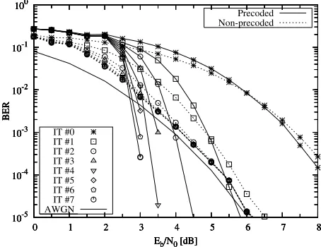
Fig. 3. BER performance of the iterative receiver using the MAP equalizer both with and without precoding
curves of both the MMSE equalizer and the MAP equalizer (without precoding) intersect with that of the outer RSC(2,1,3) decoder, before reaching the convergence point of (IAEQ = 1, IEEQ = 1). Hence residual errors may persist, regardless of both the number of iterations used and the size of the interleaver. Furthermore, the MMSE equalizer generally outputs less extrinsic information than the MAP equalizer, resulting in a poorer performance. On the other hand, with the advent of precoding, the EXIT curve of the MAP equalizer becomes capable of reaching the convergence point, as seen in Fig. 2. We note however that there is a crossover between the EXIT curves of the precoded and non-precoded MAP equalizer, which implies that the non-precoded MAP equalizer would perform better in the low-SNR region, while the precoded MAP equalizer is capable of achieving an near error-free performance, provided that a sufficiently high number of iterations is performed. The convergence threshold of the precoded MAP equalizer is about 2.3 dB.
C. Simulation results
In order to verify the convergence prediction of the EXIT chart analysis outlined in Section II-B, Monte Carlo simulations were also performed and the corresponding BER results are depicted in Fig. 3. It can be seen that the BER performance of the precoded system becomes better than that of the non-precoded system at anEb/N0 of about 2.7 dB.
III. THREE-STAGE SERIALLY CONCATENATED CODING AND MMSEEQUALIZATION
A. System model
[image:2.595.323.550.143.318.2]Mapper ISI Equalizer Decoder Encoder
I
Rate−1
II Encoder
II
Decoder I MMSE
n
Π−1 2
Π2
Π1 Π2 Π
−1 1
Π1
u1 c1 u2 c2 u3 x y
E(u3) A(c2) E(u2)
E(c1) A(u2)
E(c2)
A(c1)
A(u3)
[image:3.595.50.568.51.97.2]ˆ u1
Fig. 4. System diagram of two serially concatenated code and MMSE equalization
perform iterative equalization/decoding by exchanging extrinsic in-formation between three SISO modules, namely the MMSE equalizer, Decoder II and Decoder I of Fig. 4. Here, we would prefer not to refer to Encoder II as a precoder, since it cannot be directly combined with the equalizer at the receiver as in Fig. 1. The same three-path channel of Eq. (1) is used as in Section II. The length of the noncausal and the causal part of the MMSE filter areN1= 5andN2= 3, respectively, resulting in an overall filter length ofN=N1+N2+ 1 = 9.
B. EXIT chart analysis
In the following, we will carry out the EXIT chart analysis of the three-stage system of Fig. 4. Similar to the two-stage system, the convergence SNR threshold of the three-stage system can be determined. At the same time, the outer code is optimized to give the lowest convergence SNR threshold. Finally, the activation order of the three SISO modules is optimized.
1) Determination of the Convergence Threshold: As seen in Fig. 4, Decoder II exploits two aprioriinputs, namely,A(c2)andA(u2). At the same time, it generates two extrinsic outputs, i.e., E(c2) and E(u2). Hence, in order to describe the EXIT characteristics of Decoder II, we need the following two 2D EXIT functions [6], [7]:
IE(u2)=Tu2(IA(u2), IA(c2)), (2)
IE(c2)=Tc2(IA(u2), IA(c2)). (3) By contrast, for the MMSE equalizer and Decoder I, only one apriori input is available in Fig. 4 and the corresponding EXIT functions are:
IE(u3)=Tu3(IA(u3), Eb/N0) (4)
for the equalizer and
IE(c1)=Tc1(IA(c1)) (5)
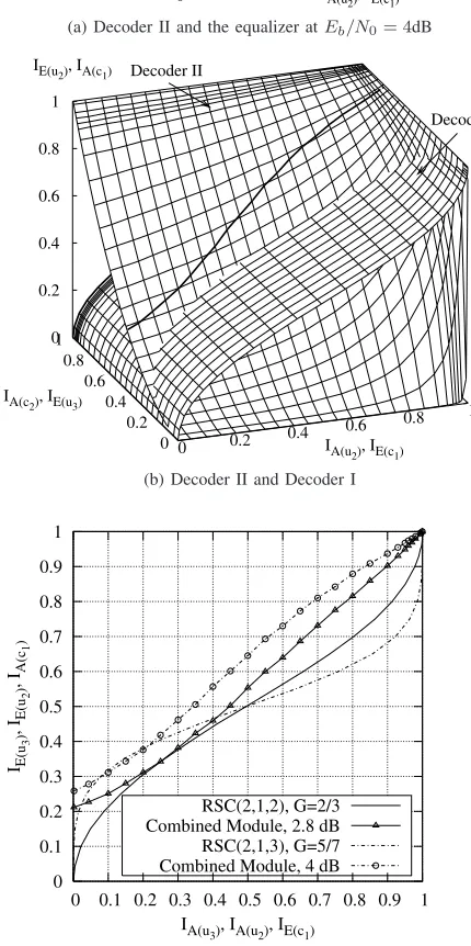
for Decoder I, where the second parameter of Eb/N0 in Eq. (4) indicates that the extrinsic information also depends on the channel SNR. Hence two 3D EXIT charts are required for plotting all the EXIT functions, namely one for the EXIT functions of both Eq. (3) and Eq. (4) as shown in Fig. 5(a), and another for the EXIT functions of both Eq. (2) and Eq. (5) as shown in Fig. 5(b). Note thatIE(u3)of Eq. (4) is independent ofIA(u2), hence the MMSE equalizer’s EXIT surface seen in Fig. 5(a) is generated by sliding its EXIT curve in the 2D EXIT chart of Fig. 2 along theIA(u2)axis. The EXIT surface of Decoder I was generated similarly, as shown in Fig. 5(b), where
IE(c1) of Eq. (5) is independent ofIA(c2).
Let us first consider the extrinsic information exchange between the MMSE equalizer and Decoder II. Letlbe the time index. Only one SISO module is invoked each time. Note that we haveIA(l)(c2) =
I(l−1)
E (u3),IA(l)(u3) =IE(l−1)(c2). Considering Eq. (2), (3) and (4), for a given aprioriinformationIA(u2), we have
I(l)
A (c2) =Tu3(Tc2(IA(u2), IAl−2(c2), Eb/N0)), (6) withIA(0)(c2) = 0and
IE(l)(u2) =Tu2(IA(u2), IA(l)(c2)). (7)
The recursive equation of (6) actually represents an iteration, including the activation of both Decoder II and the MMSE equalizer. After a sufficiently high number of iterations,IA(l)(c2)and IE(l)(u2) will converge to a value between 0 and 1, which depends on the channel SNR and on the apriori inputIA(u2)only, i.e., we have
IA(c2) = lim l→∞I
(l)
A (c2), (8)
IE(u2) = lim l→∞I
(l) E (u2)
=Tu2(IA(u2),llim→∞IA(l)(c2)). (9)
Hence the overall EXIT function of the combined module of the MMSE equalizer and Decoder II is a function ofIA(u2)andEb/N0, which can be expressed as
IE(u2) =Tu2(IA(u2), Eb/N0). (10)
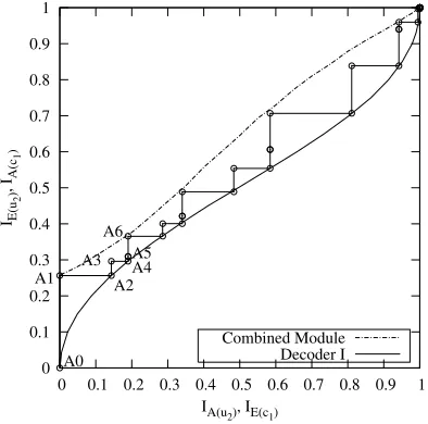
The extreme values of IA(c2) in Eq. (8), which corresponds to differentIA(u2)values can be visualized as the intersection of the two EXIT surfaces seen in Fig. 5(a), which is shown as a thick solid line. Furthermore, the EXIT function of Eq. (9) corresponding to the extreme values ofIA(c2)is shown as a solid line in Fig. 5(b). Finally, the EXIT function of Eq. (10) plotted for the combined module is shown in a 2D EXIT chart in Fig. 5(c).
From the 2D EXIT chart of Fig. 5(c), the convergence threshold of the three-stage system can be readily determined. When using a RSC(2,1,3) having octal generator polynomials of 5/7 as the outer code, the EXIT curve of the ourter code intersects with the combined EXIT curve of the equalizer and Decoder II atEb/N0= 4dB. Hence the convergence threshold of this system is around 4.1 dB. Note that it has been shown in [7] that the convergence point of a multiple-stage concatenated system is independent of the activation order of the component decoders. Hence, the convergence threshold determined in this way is the true convergence threshold, regardless of the activation order.
2) Optimization of the Outer Code: After obtaining the EXIT function of the combined module of the equalizer and Decoder II, we can optimize the outer code to provide an open tunnel between the EXIT curve of the outer code and that of the combined module at the lowest possible SNR, and hence approach the channel capacity. We carried out a code search for different generator polynomials having constraint lengths up to 5. Interestingly, we found that the relatively weak code, RSC(2,1,2) having generator polynomials of 2/3, yields the lowest convergence threshold of about 2.8 dB. The EXIT function of this code and that of the combined module atEb/N0 = 2.8dB are also shown in Fig. 5(c)
Equalizer
Decoder II
0 0.2
0.4 0.6 0.8
1
IA(u
2), IE(c1)
0 0.2 0.4 0.6 0.8 1
IA(c
2), IE(u3)
0 0.2 0.4 0.6 0.8 1
IE(c
2), IA(u3)
(a) Decoder II and the equalizer atEb/N0= 4dB
Decoder II
Decoder I
0 0.2 0.4
0.6 0.8 1
IA(u2), IE(c1)
0 0.2 0.4 0.6 0.8 1
IA(c2), IE(u3)
0 0.2 0.4 0.6 0.8 1
IE(u2), IA(c1)
(b) Decoder II and Decoder I
0 0.1 0.2 0.3 0.4 0.5 0.6 0.7 0.8 0.9 1
0 0.1 0.2 0.3 0.4 0.5 0.6 0.7 0.8 0.9 1
IE(u
3
)
, IE(u
2
)
, IA(c
1
)
IA(u
3), IA(u2), IE(c1)
RSC(2,1,2), G=2/3 Combined Module, 2.8 dB RSC(2,1,3), G=5/7 Combined Module, 4 dB
[image:4.595.51.266.230.661.2](c) 2D EXIT chart for Decoder I and the combined module of the equalizer and Decoder II
Fig. 5. EXIT charts for the three-stage SISO system.
Mapper M
U X
Π2
Π1
Fig. 6. A specific manifestation of the generic transmitter schematic seen in Fig. 4
in [7] to find the optimal activation order of multiple concatenated codes according to certain criteria, such as for example minimizing the decoding complexity. However, for the simple case of the three-stage system, we resorted to a heuristic search by invoking the EXIT functions of the three SISO modules according to different activation orders. The exchange of mutual information is between EXIT functions, hence this procedure is of very low complexity. In general, we found that by invoking more iterations between Decoder II and Decoder I while activating the MMSE equalizer from time to time, the three-stage system converges at a lower number of activations. This is not unexpected, since the error-correction capability is mainly provided by the serial concatenation of Decoder II and Decoder I. Furthermore, the MMSE equalizer is of the highest computational complexity among the three SISO modules, hence the less the MMSE equalizer is activated, the lower the total decoding complexity.
C. Simulation results
In our BER investigations, the RSC(2,1,2) code having the octal generator polynomials of (2/3) was invoked in Encoder/Decoder I. For the rate-1 Encoder II, again, the generator polynomial of 1/(1+D) was used. Fig. 6 shows a more specific manifestation of the generic schematic of the transmitter seen in Fig. 4. The block length isL=
105 bits.
Our BER results are depicted in Fig. 7. In addition to the three-stage SISO system, the BER performance of the two-three-stage SISO system of Fig. 1 using an MMSE equalizer is also shown. Observe in Fig. 7 that the two-stage SISO system performs better in the low-SNR region, while the three-stage SISO system has the edge in the medium to high SNR region, achieving an infinitesimally low BER for Eb/N0 values above 3 dB. Although the two-stage scheme is of lower decoding complexity, it cannot ”break” the AWGN BER bound, regardless of the number of iterations. To achieve a near-zero BER in the medium SNR range, the three-stage scheme has to be used.
Note that for the three-stage SISO system, the term ”iteration” has different meaning in comparison to that used in the two-stage SISO system. In our simulations, the three SISO modules of the iterative receiver are activated periodically according to a certain order. For example, in the simulations of Fig. 7, the activation order of the three SISO modules is [3 2 1 2 1 2], where the integers represent the Index (I) of the various SISO modules. Specifically,I = 3denotes the MMSE equalizer,I= 2represents Decoder II andI= 1denotes Decoder I. Finally, the above mentioned activation order of the three components is repeated twelve times.
The decoding trajectory of the three-stage SISO system recorded at
10-5 10-4 10-3 10-2 10-1 100
0 1 2 3 4 5 6
BER
Eb/N0 [dB] 10-5
10-4 10-3 10-2 10-1 100
0 1 2 3 4 5 6
BER
Eb/N0 [dB] 10-5
10-4 10-3 10-2 10-1 100
0 1 2 3 4 5 6
BER
Eb/N0 [dB] IT #0
IT #1 IT #2 IT #3 IT #4 IT #5 IT #10 IT #11 AWGN 10-5 10-4 10-3 10-2 10-1 100
0 1 2 3 4 5 6
BER
Eb/N0 [dB]
[image:5.595.64.286.42.214.2]Three-stage System Two-stage System
Fig. 7. BER performance of the three-stage SISO system of Fig. 4 and the two-stage SISO system of Fig. 1 using an MMSE equalizer.
0 0.1 0.2 0.3 0.4 0.5 0.6 0.7 0.8 0.9 1
0 0.1 0.2 0.3 0.4 0.5 0.6 0.7 0.8 0.9 1
IE(u
2
)
, IA(c
1
)
IA(u
2), IE(c1)
A0
A1 A2
A3 A4A5
A6
Combined Module Decoder I
Fig. 8. EXIT charts and decoding trajectory for the three-stage SISO system atEb/N0= 4dB.
the horizontal segments represent a single activation of Decoder I. For example, in the simulations, we used an activation schedule of [3 2 1 2 1 2 ...]. At the beginning of iterations, the equalizer was activated, but neither the value of IE(u2) nor the value of IA(c1) was changed, so the trajectory stays at the A0 point. Then Decoder II was activated, resulting in an increased value of IE(u2), hence the trajectory reaches the A1 point. Subsequently, Decoder I was activated, which increased the value of IE(c1), hence the trajectory converges to the A2 point. Similarly, the segment between A2 and A3 represents the activation of Decoder II, the segment between A3 and A4 denotes the activation of Decoder I, and the segment between A4 and A5 denotes the activation of Decoder II. The segment between A5 and A6 represents the beginning of a new iteration associated with similar decoding activations. In conclusion, we surmise that the convergence behavior of a three-stage SISO system can be adequately visualized using a 2D EXIT chart.
IV. CONCLUSIONS AND FUTURE WORK
A three-stage serially concatenated turbo scheme using an MMSE equalizer was proposed for eliminating the residual errors encoun-tered in more traditional two-stage turbo equalization schemes. The serially concatenated channel coding scheme consists of two low-complexity memory-1 codes, which nonetheless result in a significant iteration gain. The convergence behavior of this three-stage SISO system is accurately predicted by means of 3D EXIT charts as well as by its 2D projection.
The intermediate encoding stage, namely Encoder II was chosen to be recursive and to have unity rate for the sake of optimal decoding convergence, as suggested in [8]. The generator polynomials of the outer code of Encoder I were also optimized using EXIT chart analysis. For severely ISI-contaminated channels having diverse EXIT characteristics, irregular codes [10], [11] may be used as the outermost code for the sake of achieving early convergence, a topic, which constitutes our future research. Furthermore, the design method used here can be applied in the context of diverse iterative receivers, employing multiple SISO modules, such as the jointly designed source coding and space-time coded modulation schemes of [12].
ACKNOWLEDGMENT
The fruitful discussion with Andreas Wolfgang on MMSE equal-ization are gratefully acknowledged by the authors.
REFERENCES
[1] C. Douillard, M. Jezequel, C. Berrou, A. Picart, P. Didier, and A. Glavieux, “Iterative correction of intersymbol interference: Turbo equalization,”European Transactions on Telecommunications, vol. 6, pp. 507–511, Sept.-Oct 1995.
[2] K. R. Narayanan, “Effect of precoding on the convergence of turbo equalization for partial response channels,”IEEE Journal on Selected
Areas in Communications, vol. 19, no. 4, pp. 686–698, April 2001.
[3] I. Lee, “The effect of precoder on serially concatenated coding systems with an isi channel,”IEEE Transactions on Communications, vol. 49, no. 7, pp. 1168–1175, July 2001.
[4] M. T¨uchler, A. C. Singer, and R. Koetter, “Minimum mean squared error equalization using a priori information,”IEEE Transactions on Signal
Processing, vol. 50, no. 3, pp. 673–682, March 2002.
[5] M. T¨uchler, R. Koetter, and A. Singer, “Turbo equalization: Principles and new results,”IEEE Transactions on Communications, vol. 50, pp. 754–767, May 2002.
[6] S. ten Brink, “Convergence behaviour of iteratively decoded parallel concatenated codes,”IEEE Transactions on Communications, pp. 1727– 1737, Oct. 2001.
[7] F. Br¨annstr¨om, L. K. Rasmussen, and A. J. Grant, “Convergence analysis and optimal scheduling for multiple concatenated codes,”IEEE
Transactions on Information Theory, vol. 51, no. 9, pp. 3354–3364,
September 2005.
[8] M. T¨uchler, “Convergence prediction for iterative decoding of threefold concatenated systems,” inProceedings of IEEE Global
Telecommuni-cations Conference (GLOBECOM’02), Taipei, China, 17-21, November
2002, pp. 1358–1362.
[9] J. Proakis,Digital Communications, 4th ed. New York: McGraw-Hill, 2001.
[10] M. T¨uchler, “Design of serially concatenated systems depending on the block length,”IEEE Transactions on Communications, vol. 52, no. 2, pp. 209–218, February 2004.
[11] H. Jin, A. Khandekar, and R. McEliece, “Irregular repeat-accumulate codes,” inProceedings of 2nd International Symposium on Turbo Codes
and Related Topics, Brest, France, September 2000, p. 18.
[12] S. X. Ng, J. Wang, M. Tao, L.-L. Yang, and L. Hanzo, “Iteratively decoded variable-length space-time coded modulation: code construction and convergence analysis,”submitted to IEEE Transactions on Wireless
[image:5.595.76.273.265.460.2]