Adaptive MBER Space-Time DFE Assisted Multiuser Detection for SDMA Systems
S. Chen, A. Livingstone and L. Hanzo
School of Electronics and Computer Science University of Southampton, Southampton SO17 1BJ, U.K.
E-mails:{sqc,al902,lh}@ecs.soton.ac.uk
ABSTRACT
In this contribution we propose a space-time decision feedback equalization (ST-DFE) assisted multiuser detection (MUD) scheme for multiple antenna aided space division mul-tiple access systems. A minimum bit error rate (MBER) design is invoked for the MUD, which is shown to be capable of im-proving the achievable bit error rate performance over that of the minimum mean square error (MMSE) design. An adap-tive MBER ST-DFE-MUD is proposed using the least bit error rate algorithm, which is demonstrated to consistently outper-form the least mean square (LMS) algorithm, while achieving a lower computational complexity than the LMS algorithm for the binary signalling scheme. Simulation results demonstrate that the MBER ST-DFE-MUD is more robust to channel estima-tion errors as well as to error propagaestima-tion imposed by decision feedback errors, compared to the MMSE ST-DFE-MUD.
I. INTRODUCTION
In an effort to further increase the achievable system capac-ity, antenna arrays can be employed for supporting multiple users in a space division multiple access (SDMA) communications sce-nario [1]-[10]. We investigate a space-time (ST) decision feedback equalization (DFE) assisted multiuser detection (MUD) scheme for multiple receiver antenna aided SDMA systems. To interpret the multiuser-supporting capability of such a novel SDMA system [11], it is useful to relate it to classic code division multiple access (CDMA) multiuser systems [9]. In a CDMA system, each user is separated by a unique user-specific spreading code. By contrast, an SDMA system differentiates each user by the associated unique user-specific channel impulse response (CIR) encountered at the re-ceiver antennas. In this analogy, the unique user-specific CIR plays the role of a user-specific CDMA signature. However, owing to the non-orthogonal nature of the CIRs, an effective MUD is required for separating the users in an SDMA system.
The most popular SDMA-receiver design is constituted by the minimum mean square error (MMSE) MUD [5],[8]-[12]. How-ever, as recognized by [13] in a CDMA context and by [14] in an adaptive beamforming-based MUD scenario, a better strategy is to choose the detector’s coefficients by directly minimizing the system’s bit error ratio (BER). For the single-user single-antenna system, the minimum BER (MBER) equalization design has been proposed [15]-[18]. This paper studies the MBER ST-DFE-MUD in the context of SDMA and derives an adaptive MBER ST-DFE-MUD based on the least bit error rate (LBER) algorithm. It is shown that the MBER ST-DFE-MUD design results in an enhanced BER
The financial support of the EPSRC, UK and that of the European Union under the auspices of the Phoenix and Newcom projects is gratefully acknowledged.
performance in comparison to the MMSE design. Moreover, unlike the MMSE design whose performance degrades significantly owing to decision feedback errors in the presence of multi-user feedback loops, the MBER ST-DFE-MUD is very robust to the error propa-gation. The MBER ST-DFE-MUD is also shown to be more robust to channel estimation errors than the MMSE design. It is demon-strated that the LBER ST-DFE-MUD consistently outperforms the least mean square (LMS) based ST-DFE-MUD and yet it has a lower computational complexity than the latter in the case of the binary phase shift keying (BPSK) modulation scheme.
II. SYSTEMMODEL
Consider the multiple antenna aided SDMA system supporting Musers, where each of theMusers is equipped with a single trans-mit antenna and the receiver is assisted by anL-element antenna ar-ray. The symbol-rate received signal samplesxl(k)for1≤l≤L are given by
xl(k) = M
m=1 nC−1
i=0
ci,l,msm(k−i)+nl(k) = ¯xl(k)+nl(k), (1)
wherenl(k)is a complex-valued Gaussian white noise process with E[|nl(k)|2] = 2σn2, x¯l(k) denotes the noise-free part of thelth receive antenna’s output,sm(k)is thekth transmitted symbol of userm, andcl,m= [c0,l,mc1,l,m· · ·cnC−1,l,m]
T
denotes the tap vector of the CIR connecting the usermand thelth receive antenna. For notational simplicity, we have assumed that each of the (M×L) CIRs has the same length ofnC. We assume furthermore that BPSK modulation is employed and hence we havesm(k)∈ {±1}.
A bank of theM ST-DFEs constitutes the MUD, and the soft outputs of theMST-DFEs are given by
ym(k) = L
l=1 nF−1
i=0
wi,l,m∗ xl(k−i) + M
q=1 nB
i=1
b∗i,q,msˆq(k−d−i),
(2) for1 ≤ m ≤ M, wheresˆm(k)denotes the estimate ofsm(k), wl,m = [w0,l,mw1,l,m· · ·wn
F−1,l,m]
T
denotes the feedforward filter weight vector of themth user’s detector associated with the lth receive antenna, whilebq,m= [b1,q,mb2,q,m· · ·bn
B,q,m]
T
de-notes themth user’s detector feedback filter weight vector associ-ated with theqth user detector’s feedback. Again, for notational simplicity, we have assumed that each of theM ST-DFEs has the same decision delayd, all the feedforward filters have the same or-dernF, and all the feedback filters have the same ordernB. TheM detectors’ decisions are defined by
ˆ
sm(k−d) =sgn(yRm(k)),1≤m≤M, (3)
whereyRm(k) = ℜ[ym(k)]. Define xl(k) = [xl(k) xl(k−
1)· · ·xl(k−nF + 1)]T,ˆsBq(k) = [ˆsq(k−d−1)· · ·sˆq(k−
d − nB)]T, wm =
w1T,mwT2,m· · ·wL,mT T, x(k) =
xT1(k)xT2(k)· · ·xTL(k)T
,bm=
bT1,mbT2,m· · ·bTM,mT, and
ˆ
sB(k) = ˆsTB1(k) ˆs
T
B2(k)· · ·ˆs
T BM(k)
T
. Then the output of the mth ST-DFE can be written as
ym(k) = L
l=1
wHl,mxl(k) +
M
q=1
bHq,mˆsBq(k)
= wHmx(k) +bHmˆsB(k). (4)
We will choose the ST-DFE structure’s parameters as follows: d = nC−1,nF = nC andnB =nC−1. This choice of the DFE structure’s parameters is sufficient for guaranteeing that the two classes of noise-free signal states are always linearly separable at the detector’s output and therefore they guarantee an adequate performance [15]. WithnF =nCandd =nB =nC−1, let us introduce the two overall CIR matrices as
CF =
CF1 CF2 .. . CF L
and CB=
CB1 CB2 .. . CB L , (5)
whereCF
landCBlare given by
CFl= CFl,1 CFl,2 · · · CFl,M
(6)
and
CBl=
C
Bl,1 CBl,2 · · · CBl,M
, (7)
respectively, with thenF×(d+ 1)andnF×nBdimensional CIR matricesCF
l,mandCBl,mdefined by
CFl,m =
c0,l,m c1,l,m · · · cnC−1,l,m
0 c0,l,m . .. ... ..
. . .. . .. c1,l,m
0 · · · 0 c0,l,m (8) and CB l,m =
0 · · · 0
cnC−1,l,m
. .. ... ..
. . .. 0
c1,l,m · · · cnC−1,l,m
, (9)
respectively. Let us define furthermoresF(k) = [sTF1(k)s
T F2(k)· · ·
sT FM(k)]
T
, sB(k) = [sT B1(k)s
T
B2(k)· · ·s
T BM(k)]
T
andn(k) =
[n1(k) n2(k)· · ·nL(k)]T, where sFm(k) = [sm(k) sm(k − 1)· · ·sm(k −d)]T, sBm(k) = [sm(k−d−1) sm(k−d− 2)· · ·sm(k−d−nB)]Tandnl(k) = [nl(k)nl(k−1)· · ·nl(k− nF + 1)]T. Then the received signal vectorx(k)is modeled as
x(k) =CFsF(k) +CBsB(k) +n(k). (10)
Under the assumption that the past decisions are correct, we have
ˆ
sB(k) =sB(k)and the received signal vector can be expressed as x(k) =CFsF(k)+CBˆsB(k)+n(k). Thus, the decision feedback
can be viewed as a translation of the original observation spacex(k)
into a new spacer(k)[15]
r(k) △= x(k)−CBˆsB(k) =CFsF(k) +n(k)
= ¯r(k) +n(k). (11)
In the translated spacer(k), the original ST-DFE described by (4) is “translated” into a ST “linear equalizer” described as
ym(k) =wHmr(k) =w H
m(¯r(k) +n(k)) = ¯ym(k) +em(k), (12)
where em(k) is Gaussian distributed, having a zero mean and E[|em(k)|2] = 2wHmwmσn2. Note that we have r(k) =
[rT1(k)rT2(k)· · ·rTL(k)]T
withrl(k) = [rl(k)rl(k−1)· · ·rl(k− nF + 1)]T. The elements ofrl(k) can be computed recursively according to [15]
rl(k−i) =z−1rl(k−i+ 1)− M
m=1
cnC−i,l,msˆm(k−d−1),
fori=nF−1, nF−2,· · ·,1, (13) rl(k) = xl(k),
wherez−1defines the unit delay operator. The detector structure of (12) with the space translation (13) is exactly the same as the original DFE structure (4). The feedback coefficient vectorbmdoes not simply “disappear”. It has in fact been set to its “optimal value”, which isbm=−CHBwm.
III. MINIMUMBITERRORRATEMULTIUSERDETECTION
Let us denote theNs= 2M(d+1)number of possible sequences ofsF(k)ass(q),1≤q≤Ns. Denote furthermore them(d+ 1)th element ofs(q), corresponding to the symbols
m(k−d), ass( q) m,d. The noise-free part of themth detector input signal¯r(k)assumes
values from the signal set defined asRm=△{¯r(q) =CFs(q),1≤ q≤Ns}. Similarly, the noise-free part of themth detector’s output
¯
yRm(k) =ℜ[¯ym(k)]assumes values from the scalar set
YRm △
={y¯R(qm) =ℜ[w
H m¯r
(q)
],1≤q≤Ns}. (14)
The probability density function (PDF) ofyRm(k)is a Gaussian
mixture given by [13],[14]
pm(yR) =
1
Ns
√ 2πσn
wH
mwm Ns
q=1 e−
yR−y¯
(q)
Rm
2
2σ2
nwH
mwm
, (15)
wherey¯(Rqm) ∈ YRm. Thus the BER of themth ST-DFE associated
with weight vectorwmis given by
PE(wm) =
1
Ns Ns
q=1
QgR(q)(wm)
, (16)
whereQ(•)is the usual errorQ-function and
gR(q)(wm) =
sgn(s(m,dq) )¯y
(q)
Rm
σn
wH mwm
=sgn(s
(q)
m,d)ℜ[w H m¯r(q)]
σn
wH mwm
-6 -5 -4 -3 -2 -1 0
-10 -5 0 5 10
log10(Bit Error Rate)
SNR (dB) MMSE(1)-DF
MMSE(1) MBER(1)-DF MBER(1)
-6 -5 -4 -3 -2 -1 0
-10 -5 0 5 10
log10(Bit Error Rate)
SNR (dB) MMSE(2)-DF
MMSE(2) MBER(2)-DF MBER(2)
-6 -5 -4 -3 -2 -1 0
-10 -5 0 5 10
log10(Bit Error Rate)
SNR (dB) MMSE(3)-DF
MMSE(3) MBER(3)-DF MBER(3)
-6 -5 -4 -3 -2 -1 0
-10 -5 0 5 10
log10(Bit Error Rate)
SNR (dB) MMSE(4)-DF
[image:3.595.127.471.448.576.2]MMSE(4) MBER(4)-DF MBER(4)
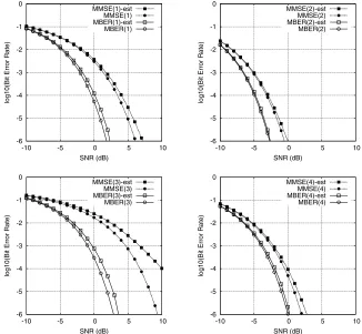
Fig. 1. Theoretical and simulated bit error rate comparison of the MMSE and MBER ST-DFE-MUDs for users 1 to 4 of the 4-user 4-antenna time-invariant system, where DF indicates simulated BER with detected symbols being fed back.
TABLE I
SYSTEM’SCIRS FOR A4-ANTENNA4-USER TIME-INVARIANTSDMASYSTEM.
Cl,m(z) m= 1 m= 2 m= 3 m= 4
l= 1 (0.6 +j0.7) (−0.1−j0.2) (0.7 +j0.5) (0.8−j0.4) +(0.8 +j0.5)z−1 +(0.4 +j0.5)z−1 +(0.6 +j0.4)z−1 +(
−0.6 +j0.5)z−1 +(0.3 +j0.4)z−2 +(0.3
−j0.2)z−
2
+(0.5 +j0.5)z−2 +(0.3 +j0.3)z−2 l= 2 (0.1 +j0.2) (0.9 +j0.2) (−0.3−j0.3) (0.3 +j0.3)
+(0.4 +j0.3)z−1 +(0.3 +j0.7)z−1 +(0.4 +j0.2)z−1 +(0.4 +j0.4)z−1 +(0.5 +j0.4)z−2 +(0.2 +j0.2)z−2 +(
−0.2 +j0.4)z−2 +(0.5 +j0.5)z−2
l= 3 (−0.1 +j0.3) (0.5 +j0.6) (0.2−j0.3) (0.1 +j0.8) +(0.6−j0.5)z−1 +(−0.3−j0.4)z−1 +(0.4−j0.5)z−1 +(0.7 +j0.6)z−1 +(0.2 +j0.4)z−2 +(0.2 +j0.4)z−2 +(0.6 +j0.3)z−2 +(0.8 +j0.5)z−2 l= 4 (0.8 +j0.9) (0.4 +j0.4) (0.1 +j0.2) (0.4 +j0.6)
+(0.6 +j0.5)z−1 +(0.4 +j0.4)z−1 +(
−0.3−j0.4)z−1 +(0.5 +j0.3)z−1 +(0.5 +j0.3)z−2 +(0.4 +j0.4)z−2 +(0.3 +j0.2)z−2 +(0.2 +j0.3)z−2
Note that the BER is invariant to a positive scaling ofwm.
The MBER solution for themth detector is then defined as the weight vector that minimizes the error probability (16)
w(MBER)m= arg min
wm
PE(wm). (18)
The gradient ofPE(wm)with respect towmis given by
∇PE(wm) =
1
2Ns
√ 2πσn
wH
mwm Ns
q=1 e−
¯
y(q) Rm
2
2σ2nwH
mwm
×sgns(m,dq)
¯
y(Rqm)wm wH
mwm −
¯
r(q)
. (19)
Given the gradient (19), the optimization problem (18) can be solved iteratively by commencing from an appropriate initialization point using a gradient optimization algorithm. The simplified con-jugate gradient algorithm of [19],[13] provides an efficient means of finding an MBER solution for the optimization problem (18).
IV. ADAPTIVEMINIMUMBITERRORRATEIMPLEMENTATION
The Parzen window method [20]-[22] provides an efficient means of estimating a PDF. Given a block ofKtraining samples
PDF in (15) takes the form
˜
pm(yR) =
1
K√2πρn K
k=1 e−
(yR−yRm(k))
2
2ρ2n , (20)
whereρ2
n is the chosen kernel variance. Based on the estimated PDF (20), an approximate BER is given by
˜
PE(wm) =
1
K K
k=1
Q˜gR(k)(wm)
(21)
with
˜
g(Rk)(wm) =
sgn(sm(k−d))yRm(k)
ρn
. (22)
This approximation is an adequate one, provided that the widthρn is chosen appropriately.
To derive a sample-by-sample adaptive algorithm for updating the detector’s weight vectorwm, consider a single-sample estimate ofpm(yR)
˜
pm(yR, k) =
1 √
2πρn e−
(yR−yRm(k))
2
2ρ2n . (23)
Conceptually, from this single-sample PDF “estimate”, we have a single-sample or instantaneous BER “estimate”P˜E(wm, k). Using the instantaneous stochastic gradient∇P˜E(wm, k)gives rise to a stochastic gradient adaptive algorithm, which we referred to as the LBER algorithm
wm(k+ 1) =wm(k) +µsgn(sm(k−d))
2√2πρn e−
y2 Rm(k)
2ρ2n r(k). (24)
The adaptive gainµas well as the kernel widthρnare the two al-gorithmic parameters that have to be set appropriately. Specifically, they are chosen to ensure adequate performance in terms of both the achievable convergence rate and steady-state BER misadjust-ment. Note that there is no need to normalize the weight vector to a unit-length after each update. It can readily be shown that for the BPSK case, the LBER ST-DFE is computationally simpler than the LMS ST-DFE, imposing about half the computational complexity required by the LMS algorithm [14].
V. SIMULATIONSTUDY
Time-invariant system. The system supportedM = 4users with L = 4receiver antennas. The 16 CIRs are listed in Table I, each having nC = 3taps. In the simulations all the 16 CIRs were normalized usingCl,m(z)/|Cl,m(z)|to provide a channel gain of unity. As the length of the CIRs wasnC = 3, the ST-DFE struc-ture was defined bynF = 3,d = 2andnB = 2. The theoret-ical BER curves of the MMSE and MBER ST-DFE-MUDs, com-puted using the BER expression of (16), are plotted in Fig. 1 over a range of signal to noise ratio (SNR) conditions. It can be seen that the MBER ST-DFE-MUD provided better BER performance than the MMSE ST-DFE-MUD. The BER calculated using the ex-pression (16) represents the theoretical best-case performance, since it was obtained assuming that the correct symbols were fed back
in the ST-DFE-MUD’s feedback loop. For the sake of investigat-ing the effects of decision feedback induced error propagation, the BERs of the MMSE and MBER ST-DFE-MUDs were also calcu-lated using simulations with the error-prone detected symbols being fed back, and the results are also depicted in Fig. 1, in comparison to the corresponding theoretical best-case performance. It can be seen that the MBER ST-DFE-MUD is significantly more robust to error propagation than the MMSE ST-DFE-MUD. We also added the Gaussian white noise with standard deviation 0.1 to each tap of the CIRs to represent channel estimation errors. The theoreti-cal BERs of the MMSE and MBER ST-DFE-MUDs obtained based on the “estimated” CIRs and averaged over 10 “estimations” are illustrated in Fig. 2, in comparison to the performance derived us-ing perfect channel knowledge. It can be seen that the performance degradation due to imperfect channel estimates is less serious for the MBER ST-DFE-MUD than for the MMSE one.
Slow fading system. The system again supported 4 users with 4 receive antennas. However, fading channels were simulated and each of the 16 CIRs hadnC = 3taps. Magnitudes of the CIR taps were uncorrelated Rayleigh processes, each having the root mean power of√0.5 +j√0.5. The normalized Doppler frequency for the simulated system was10−6
, which for a carrier of 900 MHz and a symbol rate of 3 Msymbols/s corresponded to a user veloc-ity of 1 m/s (3.6 km/h). Continuously fluctuating fading was used, which provided a different fading magnitude and phase for each transmitted symbol. The ST-DFE structure parameters were set to d= 2,nF = 3andnB = 2. The step size for the LMS algorithm was chosen asµ = 0.005, while for the LBER algorithm the step sizeµ = 0.1and kernel varianceρ2n = 9σn2. The transmission frame structure consisted of 50 training symbols followed by 450 data symbols. The BER of an adaptive ST-DFE-MUD was calcu-lated using Monte Carlo simulation with the detected symbols been fed back. Fig. 3 compares the BER of the LBER ST-DFE-MUD for user 2 with that of the LMS based one. The BERs for the other three users, not shown here due to space limitation, are similar to the BER for user 2 shown in Fig. 3. It can be seen that the LBER ST-DFE-MUD consistently outperformed the LMS ST-DFE-MUD.
VI. CONCLUSIONS
A novel minimum bit error rate design has been proposed for the ST-DFE-MUD employed in multiple antenna aided SDMA sys-tems. It has been demonstrated that this MBER design is capable of achieving better performance and hence of improving the attain-able system capacity, compared to the MMSE design. An adaptive implementation of the MBER ST-DFE-MUD has also been derived based on the LBER algorithm, which has been shown to consis-tently outperform the LMS algorithm and yet maintaining a lower computational complexity than the latter for BPSK modulation. An-other interesting result observed in this study is that the MBER ST-DFE-MUD is significantly more robust against the error prop-agation caused by error-prone detected symbols used in the MUD’s feedback loop, in comparison to the MMSE ST-DFE-MUD.
REFERENCES
-6 -5 -4 -3 -2 -1 0
-10 -5 0 5 10
log10(Bit Error Rate)
SNR (dB) MMSE(1)-est
MMSE(1) MBER(1)-est MBER(1)
-6 -5 -4 -3 -2 -1 0
-10 -5 0 5 10
log10(Bit Error Rate)
SNR (dB) MMSE(2)-est
MMSE(2) MBER(2)-est MBER(2)
-6 -5 -4 -3 -2 -1 0
-10 -5 0 5 10
log10(Bit Error Rate)
SNR (dB) MMSE(3)-est
MMSE(3) MBER(3)-est MBER(3)
-6 -5 -4 -3 -2 -1 0
-10 -5 0 5 10
log10(Bit Error Rate)
SNR (dB) MMSE(4)-est
[image:5.595.132.458.95.396.2]MMSE(4) MBER(4)-est MBER(4)
Fig. 2. Theoretical bit error rate comparison of the MMSE and MBER ST-DFE-MUDs for users 1 to 4 of the 4-user 4-antenna time-invariant system, where est indicates imperfect channel estimates were used.
−5 0 5 10 15
10−5
10−4
10−3
10−2
10−1
100
Average SNR (dB)
BER
LMS(2) LBER(2)
Fig. 3. Simulated bit error rate comparison of the LMS and LBER ST-DFE-MUDs for user 2 of the 4-user 4-antenna slow fading system.
[2] A.J. Paulraj and C.B. Papadias, “Space-time processing for wireless communications,”IEEE Signal Processing Magazine, Vol.14, No.6, pp.49–83, 1997.
[3] G. Tsoulos, M. Beach and J. McGeehan, “Wireless personal communications for the 21st cen-tury: European technological advances in adaptive antennas,”IEEE Communications Maga-zine, Vol.35, No.9, pp.102–109, 1997.
[4] J.H. Winters, “Smart antennas for wireless systems,”IEEE Personal Communications, Vol.5, No.1, pp.23–27, 1998.
[5] A.J. Paulraj and B.C. Ng, “Space-time modems for wireless personal communications,”IEEE Personal Communications, Vol.5, No.1, pp.36–48, 1998.
[6] P. Vandenameele, L. van Der Perre and M. Engels,Space Division Multiple Access for Wireless Local Area Networks. Boston: Kluwer Academic Publishers, 2001.
[7] J.S. Blogh and L. Hanzo,Third Generation Systems and Intelligent Wireless Networking – Smart Antenna and Adaptive Modulation. Chichester: John Wiley, 2002.
[8] A. Paulraj, R. Nabar and D. Gore,Introduction to Space-Time Wireless Communications.
Cam-bridge: Cambridge University Press, 2003.
[9] L. Hanzo, L-L. Yang, E-L. Kuan and K. Yen,Single- and Multi-Carrier DS-CDMA: Multi-User Detection, Space-Time Spreading, Synchronisation, Standards and Networking. IEEE Press -John Wiley, 2003.
[10] A.J. Paulraj, D.A. Gore, R.U. Nabar and H. B¨olcskei, “An overview of MIMO communications – A key to gigabit wireless,”Proc. IEEE, Vol.92, No.2, pp.198–218, 2004.
[11] L. Hanzo, M. M¨unster, B.J. Choi and T. Keller,OFDM and MC-CDMA. West Sussex, England: John Wiley and IEEE Press, 2003.
[12] D.N.C. Tse and S.V. Hanly, “Linear multiuser receivers: effective interference, effective band-width and user capacity,”IEEE Trans. Information Theory, Vol.45, No.2, pp.641–657, 1999. [13] S. Chen, A.K. Samingan, B. Mulgrew and L. Hanzo, “Adaptive minimum-BER linear
mul-tiuser detection for DS-CDMA signals in multipath channels,”IEEE Trans. Signal Processing, Vol.49, No.6, pp.1240–1247, 2001.
[14] S. Chen, N.N. Ahmad and L. Hanzo, “Adaptive minimum bit error rate beamforming,”IEEE Trans. Wireless Communications, Vol.4, No.2, pp.341–348, 2005.
[15] S. Chen, B. Mulgrew, E.S. Chng and G. Gibson, “Space translation properties and the minimum-BER linear-combiner DFE,”IEE Proc. Communications, Vol.145, No.5, pp.316– 322, 1998.
[16] C.C. Yeh and J.R. Barry, “Adaptive minimum bit-error rate equalization for binary signaling,” IEEE Trans. Communications, Vol.48, No.7, pp.1226–1235, 2000.
[17] B. Mulgrew and S. Chen, “Adaptive minimum-BER decision feedback equalisers for binary signalling,”Signal Processing, Vol.81, No.7, pp.1479–1489, 2001.
[18] S. Chen, L. Hanzo and B. Mulgrew, “Adaptive minimum symbol-error-rate decision feed-back equalization for multi-level pulse-amplitude modulation,”IEEE Trans. Signal Processing, Vol.52, No.7, pp.2092–2101, 2004.
[19] M.S. Bazaraa, H.D. Sherali and C.M. Shetty,Nonlinear Programming: Theory and Algorithms. New York: John Wiley, 1993.
[20] E. Parzen, “On estimation of a probability density function and mode,”The Annals of Mathe-matical Statistics, Vol.33, pp.1066–1076, 1962.
[21] B.W. Silverman,Density Estimation. London: Chapman Hall, 1996.
[image:5.595.96.236.437.581.2]