This is a postprint of a paper published in IEEE Xplore [http://dx.doi.org/10.1109/ESTS.2011.5770869] and is subject to IEEE copyright.
The Use of Real Time Digital Simulation and
Hardware in the Loop to De-Risk Novel Control
Algorithms
S. Loddick, U. Mupambireyi
Converteam UK LtdRugby, UK
S. Blair, C. Booth, X. Li, A. Roscoe
University of StrathclydeGlasgow, UK
K. Daffey, Lt J. Watson RN
UK Ministry of Defence Abstract—Low power demonstrators are commonly used tovalidate novel control algorithms. However, the response of the demonstrator to network transients and faults is often unexplored. The importance of this work has, in the past, justified facilities such as the T45 Shore Integration Test Facility (SITF) at the Electric Ship Technology Demonstrator (ESTD). This paper presents the use of real time digital simulation and hardware in the loop to de-risk a innovative control algorithm with respect to network transients and faults. A novel feature of the study is the modelling of events at the power electronics level (time steps of circa 2 µs) and the system level (time steps of circa 50 µs).
I. INTRODUCTION
Converteam has designed, built and tested a 150 kW Active Stator demonstrator. Active Stator is a novel variable speed drive architecture, ideally suited to marine propulsion application [1].Testing of the 150 kW demonstrator included planned application level testing (e.g. crash reversals, picking up a spinning propeller etc.). A major limit of the testing programme was the lack of power network transient and fault testing. The UK Ministry of Defence (MOD) funded the Advanced Propulsion Motor System (APMS), to deliver a 15 MW tandem Active Stator propulsion motor that will be tested in a back-to-back configuration [2]. Again the testing of the control hardware and software will be limited to “normal” operations. Discussions identified a desire to further de-risk the APMS control hardware and software, particularly with regard to its operation in, and interaction with, a naval combatant power and propulsion system, which is exposed to a range of electrical network transients and faults. This led to the MOD funded APMS RTDS study which combines Real Time Digital Simulation (RTDS) with hardware in the loop (HIL) to de-risk the performance of representative APMS control hardware and software in response to a range of electrical network transients and faults. This study has been undertaken by Converteam and the University of Strathclyde. A major challenge was simulating the power system and power system transients, and the electronic commutator and network bridge, with
sufficient fidelity. This paper discusses some of the challenges and how they were overcome and presents some of the results, before concluding on the success of the study to date and highlighting some of the opportunities of RTDS and HIL.
II. SYSTEM UNDER TEST
A. Single Line Diagram
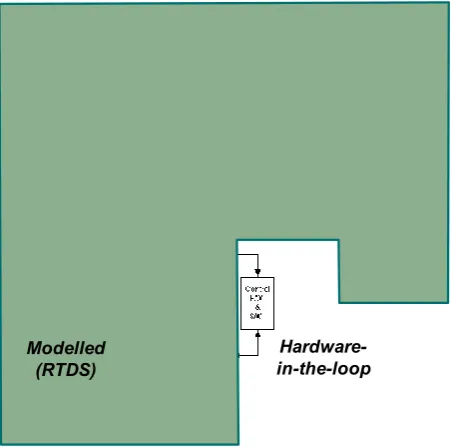
The power and propulsion system under test is illustrated in Fig. 1 below. Although simplified, and limited (by the availability of controller hardware) to a single APMS, the system includes all of the major elements of a typical power and propulsion system that could be applied on a surface combatant such as the planned UK Type 26 Frigate[3].
Modelled (RTDS)
[image:1.595.332.559.445.669.2]Hardware-in-the-loop
This is a postprint of a paper published in IEEE Xplore [http://dx.doi.org/10.1109/ESTS.2011.5770869] and is subject to IEEE copyright.
B. Components of the System The system comprises:
Four off prime movers:
- One high power Gas Turbine Alternator (GTA). - Three low power Diesel Generators (DGs).
Two individual hotel loads (Hotel Load 1 and 2), each a linear hotel load (no harmonic content), purely motoring, no regeneration.
The GTA and DGs are required for sprint evolutions, and the DGs alone required for cruise. The prime movers are connected via individual circuit breakers to a three phase AC distribution system
The hotel load has been separated to allow future work to differentiate between linear and non-linear hotel load. Whilst it was not the intention of the study to develop prime mover control algorithms to maintain power quality throughout network transients, future work – where there is a clear definition of the power and propulsion system (AC or DC) and power quality requirements – has the opportunity to include a non-linear load that regenerates as well as motors, and is relatively rich in harmonics. This will help identify scenarios that may require further investigation.
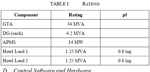
[image:2.595.320.551.208.282.2]C. Ratings
TABLE I. RATINGS
Component Rating pf
GTA 34 MVA DG (each) 4.2 MVA APMS 34 MW
Hotel Load 1 1.25 MVA 0.8 lag Hotel Load 2 1.25 MVA 0.8 lag
D. Control Software and Hardware 1) Control Software Overview
Whilst the drive architecture is novel, the APMS control scheme is similar to that of a separately excited mechanically commutated DC machine and is partitioned into three sections: field control; armature control; and commutator control.
The Active Stator machine is vector controlled with stator flux orientation. The machine is controlled to deliver maximum torque per ampere for a given operating flux level. The machine is operated as a speed controlled drive with dedicated controllers for speed, DC link current, stator flux, field current and electronic commutator. The machine operating power factor is controlled through the electronic commutator phase control.
The electronic commutator is controlled to act in a similar manner to the rotating mechanical commutator and stationery brushes of a classical DC machine, switching the DC link current into the appropriate machine stator coils to generate torque. It runs at the variable voltage and frequency
of the machine. With phase control, four quadrant motor operation can be achieved by operating as either a rectifier or an inverter. When motoring, the electronic commutator is inverting DC link power to AC machine power. When generating, it is rectifying AC machine power to DC link power [1].
2) Control Hardware Overview
Following successful testing at the University of Nottingham and Electric Ship Technology Demonstrator (ESTD), the controller from the 150 kW demonstrator was reused as the HIL in the APM RTDS study. The major elements of the control hardware are illustrated in Fig. 2 below.
FIRING SIGNALS DIGITAL & ANALOG I/Os
OPERATOR’S COMMANDS
Local Control Panel CPU Controller I/O Slices [Beckhoff]
FAST DIGITAL & ANALOG I/Os CONTROL
SCHEME
Power Interface Boards FIRING SIGNALS DIGITAL & ANALOG I/Os
OPERATOR’S COMMANDS
Local Control Panel CPU Controller I/O Slices [Beckhoff]
FAST DIGITAL & ANALOG I/Os CONTROL
SCHEME
[image:2.595.32.284.368.489.2]Power Interface Boards
Figure 2. Major Elements of Control Hardware
III. IMPLEMENTATION
The real time digital simulator employed for the study was the RTDS® Simulator produced by RTDS Technologies [4].
The dedicated Real-time System Computer Aided Design (RSCAD) [5] software is a real-time version of the Power System Computer Aided Design (PSCAD) simulation software [6]. It is a dedicated modelling package for use with the RTDS and provides the main interface to the RTDS. It has a graphical user interface and has extensive model libraries that permit a wide range of electrical system architectures and components to be modelled.
RSCAD was used to model the components of the system highlighted in Fig. 1 above.
Several of the RSCAD libraries are employed in the model: the power system component library; the control system component library; and the small time step component library, which was key to this particular project’s requirements.
The main power system simulations within RSCAD and the RTDS normally operate with a 50 µs time step. However, the small time step simulations, which interface with the power system simulation, and are used to accurately represent high frequency switching and circuit dynamics within power electronics based power conversion systems, operate with time steps in the range 1 to 4 μs.
This is a postprint of a paper published in IEEE Xplore [http://dx.doi.org/10.1109/ESTS.2011.5770869] and is subject to IEEE copyright.
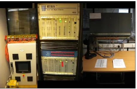
Figure 3. Modelling, Simulation, and HIL Laboratory Arrangment
IV. LIMITATIONS
The APMS RTDS study was not intended to de-risk the Active Stator power electronic topology, or the operation of the control hardware and software in producing firing patterns to control the topology. That work has already been completed as part of the design, assembly and test of the 150 kW Active Stator demonstrator that has successfully operated on an AC supply at the University of Nottingham, and a DC supply at ESTD. The APMS RTDS study was intended to de-risk the integration of an APMS into a representative naval combatant power and propulsions system, albeit with a single shaft line. That is not to say that RTDS cannot be used to de-risk a power electronics topology, but such work would require more detailed device models, and potentially faster execution times (reduced time steps). It may be necessary to use an alternative RTDS system geared towards real time simulation of power electronics.
A limitation of the implementation was the lack of an overall Power Management System (PMS), and no attempt has been made to optimise the speed and voltage droop control of the generator models.
There were two further limitations:
The 150 kW demonstrator did not have a dynamic brake resistor (DBR), instead regenerating to the network during transient operations. With no proven control hardware and software, this meant the APMS implemented on the RTDS was also limited to regenerative braking, when rheostatic braking might be more appropriate with a relatively low hotel load compared to propulsion load.
With the 150 kW demonstrator developed for operation at industrial sites, the software required to provide a droop characteristic1 (present in drives intended for marine application) was not included.
1 Automatic shedding of propulsion load, or limit of propulsion load, by
drive control in the event of limited generation capacity.
V. TESTING
A. Introduction
The test programme was developed with input from all stakeholders: Converteam; MOD; and the University of Strathclyde. Lloyd’s Register rules [6] were also consulted to help define the test programme.
Tests were divided into steady state, transient, and faults. 1) Steady State
Voltage, permanent variations, +6%, -10%.
Frequency, permanent variations, ±5%. 2) Transient
Voltage, permanent variations, ±20%, recovery time 1.5 seconds.
Frequency, permanent variations, ±10%, recovery time 5 seconds, maximum rate of change 1.5 Hz .s-1.
Acceleration to full speed followed by crash reversal2.
Loss of prime mover. (Loss of DG if in cruise, loss of GTA or DG if in sprint.)
Addition of prime mover. (For example the addition of GTA when accelerating from cruise to sprint.)
Loss of hotel load.
Addition of hotel load.
Phase imbalance, 10% for 2 s.
Droop characteristic. 3) Faults
Single phase to earth.
Three phase to earth.
Phase to phase short.
Three phase short.
All fault tests considered varying fault locations, clearance times and points on waveform of fault inception.
VI. RESULTS
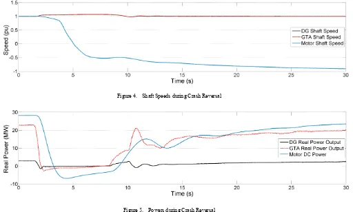
As an example of the results generated, Figs. 4 and 5 below illustrate a successful crash reversal.
All tests were successfully completed, although with the limitations identified earlier, not all the results illustrated the behaviour that would be observed on a naval application. For example with the lack of droop control, the response to loss of a prime mover was not representative of the behaviour observed on numerous platforms where droop control has been successfully implemented.
2 Crash reversal: Starting full speed ahead, to braking ahead (down to zero
This is a postprint of a paper published in IEEE Xplore [http://dx.doi.org/10.1109/ESTS.2011.5770869] and is subject to IEEE copyright.
Figure 4. Shaft Speeds during Crash Reversal
Figure 5. Powers during Crash Reversal
VII. VERIFICATION AND VALIDATION
A. Power System Models
The RTDS, like many digital electromagnetic transient simulators, uses algorithms based on the Dommel equations to represent power systems [8]. This approach is well understood and widely accepted. Many of the power system components used in this project, such as the synchronous machine, excitation systems, GTA governor, and circuit breaker models, are provided by RTDS Technologies and have been used extensively in the past [9]. Therefore detailed verification of each power system model is not considered further in this paper.
B. RTDS APM Mode Verification
The RTDS APMS model was verified, to an extent, by comparing the theoretical (steady state) rated values for several parameters with the values obtained through simulation.
TABLE II. RTDSAPMSMODEL VERIFICATION
Property Rated Value Results
Rated drive DC
voltage 5.00 kV 4.26 kV Rated drive DC link
current 6.8 kA 6.6 kA
Motor phase voltage 420 V 420 V Rated DC field current 500 A 500 A
Table II above illustrates some of the results used to verify the RTDS APMS model. Whilst some of the results match precisely, there is a discrepancy in the DC link voltage and current which merits further future investigation which at the time of writing a lack of time has prevented. However, it is believed to a result of overestimate the (non-linear) airgap flux in the RTDS implementation of the APM.
VIII. OBSERVATIONS
A. Introduction
Overall the results have illustrated that the APMS control is satisfactorily robust, responding as expected and as hoped to the network transients and faults. The major exception was the expected response to loss of a prime mover with no droop control implemented in the control software.
[image:4.595.58.559.57.184.2]This is a postprint of a paper published in IEEE Xplore [http://dx.doi.org/10.1109/ESTS.2011.5770869] and is subject to IEEE copyright.
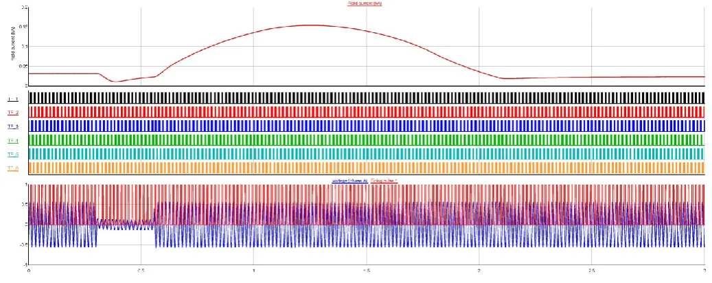
Figure 6. Results Illustrating Exciter Overcurrent
B. APMS Speeding up on Fault Clearance
The APMS tends to speed up after a fault is cleared. This was caused by the field current increasing above its reference value on fault clearance. This resulted in increased motor voltage and consequently motor air gap flux and torque, ultimately causing the motor to speed up.
On the 150 kW demonstrator, the drive controller regulates the field current and sends an analogue voltage reference to a (commercial off the shelf) six-pulse thyristor bridge rectifier (field converter), which has a limited signal sampling and firing pulse update rate. This constraint imposed a low limit on the field current control bandwidth resulting in sluggish field current response during transient non-linear events. Fig. 4 includes some of the results used to diagnose this behaviour, illustrating from top to bottom: field current; thyristor firing pulses for the six-pulse rectifier; and the network voltage indicating the application of the fault. When the fault occurs, the field current controller tries to compensate for the drop in field current, by demanding more field volts. When the fault is cleared, owing to the low bandwidth, the field takes time to wind the voltage down, resulting in the field current increasing above the reference before it eventually settles to the commanded value.
The 15 MW APMS was designed with a different excitation system (to the 150 kW demonstrator) to enable a more robust response to steady state, transient and fault conditions including:
Use of field converters with higher control bandwidth.
Modified field control strategy to include detection logic for non linear events (e.g. large transient variations in network volts or frequency) enabling the control system to adapt its synchronisation logic, field current referencing and controller gains to cope with such dynamic system variations.
Following review, this behaviour is not expected to be repeated on the 15 MW APMS.
In conclusion, this illustrates the ability of RTDS and HIL to highlight interactions that might not be observed in a lower power demonstrator during normal operations.
C. Controller Parameterisation
When the model parameters were scaled up from the 150 kW demonstrator to the 34 MVA APMS model, drive controller parameters also required modification. For example, most of the control loop gains required retuning owing to the changes in plant parameters such as motor inertia, impedance values, voltage, and current levels. To this end, the University of Strathclyde was given access to the controller to enable the parameter changes to be made with standard diagnostic tools, with Converteam providing remote support to facilitate rapid completion of this parameterisation process.
IX. DISCUSSION
The majority of the time was spent converting the APMS model to run on the RTDS and integrating the 150 kW demonstrator controller as HIL, before commissioning the system. Once successfully commissioned, simulating the steady state and transient behaviour and faults was relatively quick. With the RTDS scripting and automation features, circa 50 tests / hour can be conducted. Analysis of the results is much more time consuming, and the task of model verification must not be neglected or underestimated.
This is a postprint of a paper published in IEEE Xplore [http://dx.doi.org/10.1109/ESTS.2011.5770869] and is subject to IEEE copyright.
X. CONCLUSIONS
It has been possible to integrate an APMS controller as HIL with the RTDS and to model a simple representation of a naval combatant vessel power and propulsion system.
The HIL and RTDS system has been successfully used to provide indicative results from modelling the steady state and transient performance of the APMS, and to start to explore the system’s response to network transients and faults. A response not investigated during operation of the 150 kW power demonstrator.
The modelling has revealed aspects of performance that have not been observed during testing of the 150 kW demonstrator at either the University of Nottingham or ESTD where network faults have not occurred (intentionally or unintentionally). In some cases this has allowed the control methodology to be modified before APM testing.
RTDS and HIL has demonstrated its effectiveness as a low cost means of de-risking power and propulsion topologies and associated control algorithms, and can be considered as a useful precursor to, or complementary to, the design and build of full scale Shore Integration Test Facilities (SITF).
XI. OPPORTUNITES
Whilst limited in scope, the APM RTDS contract has demonstrated that RTDS and HIL can be used as part of the de-risking of the control hardware and software of a power electronic based marine propulsion system. There are a number of potential opportunities to exploit the work completed to date.
A. Increased Hardware and HIL
Increase RTDS hardware and HIL to enable a more representative system to be modelled. The system under test can be made more representative in two steps:
Additional RTDS hardware and HIL (controller) to model a second APMS.
Additional HIL to include protection relays, prime mover \ generator control etc..
Modelling two propulsion motors would enable system interactions to be investigated, particularly the impact of loss of one propulsion motor on the continued operation of the second.
Expanding the HIL to include hardware from multiple suppliers significantly increases the value of the system under test in risking system integration. For example, de-risking new protection strategies, potentially reducing the extent of SITFs and certainly de-risking the SITF.
B. Increased Accuracy of Ship Model
The current ship model is very simple. A more accurate model would allow improved predictions of ship performance and improve the degree to which controller parameters can be tuned before sea trials.
C. Topology Comparison
With RTDS and HIL it is a relatively easy and low cost to model multiple power and propulsion system topologies. Unlike a SITF, in all likelihood dedicated to a single topology, RTDS can be used to investigate multiple topologies during project concept design stages. Any investment in RTDS hardware can be reused, being reprogrammed for the different topologies. Whilst different sets of HIL hardware are likely to be required, the cost of the control hardware and software is generally a small fraction of the cost of the equipment it controls, particularly if no or minimal development is required. It is possible to envisage an RTDS being used to investigate the performance of multiple topologies, helping in the down select.
D. Fault Finding
Once established, RTDS and HIL can be used to model faults very quickly; the biggest challenge becomes handling the volume of data produced. Events that might be very rare at sea, perhaps occurring in a class of vessel once per year, can be investigated in less than a day, and at zero risk to the vessel(s). Diagnostic data recorded at the vessel can be compared and contrasted with the data gathered from the RTDS and HIL. Captured in-service data can also be used for ongoing model verification, validation and refinement. E. Training.
RTDS and HIL can also be used to train operators. The HIL can be the actual hardware the operators will use on the vessel, and with provision for an instructor to introduce events, the operators can be trained in terms of the system’s response to faults, and the appropriate corrective action.
ACKNOWLEDGMENTS
The authors acknowledge the Directors of Converteam UK Ltd, the UK Ministry of Defence and the University of Strathclyde for their permission to publish this paper. They would also like to thank RTDS Technologies and numerous colleagues for their valuable assistance and contributions.
REFERENCES
[1] D. Lee, S. Loddick, U. Mupambireyi, and S. Ouchouche “Active Stator, an innovative variable speed drive topology”, PEMD, April 2010.
[2] S. Loddick and Lt J. Watson, “APM, a new generation of ship propulsion motor”, INEC, May 2010.
[3] UK MOD, “Strategic defence and security review – securing Britain in an age of uncertainty”, October 2010.
[4] http://www.rtds.com/hardware/hardware.html. [5] http://www.rtds.com/software/rscad/rscad.html. [6] https://pscad.com/products/pscad/.
[7] Lloyd’s Register, “Rules and regulations for the classification of naval ships”, January 2008.
[8] Dommel H., “Digital computer simulation of electromagnetic transients in single and multiphase networks”, IEEE Transactions on Power Apparatus and Systems, 1969.