A FAST METHOD FOR COMPUTING THE OUTPUT OF RANK ORDER FILTERS
WITHIN ARBITRARILY SHAPED WINDOWS
Paul Murray and Stephen Marshall
Department of Electronic and Electrical Engineering, University of Strathclyde Royal College Building, 204 George Street, G1 1XW, Glasgow, Scotland
phone: + 44 (0) 141 548 2205, fax: +44 (0) 141 552 2487, email: [email protected] web: www.strath.ac.uk/eee/research/cesip/
ABSTRACT
Rank order filters are used in a multitude of image process-ing tasks. Their application can range from simple pre-processing tasks which aim to reduce/remove noise, to more complex problems where such filters can be used to detect and segment image features. There is, therefore, a need to develop fast algorithms to compute the output of this class of filter. A number of methods for efficiently computing the
output of specific rank order filters have been proposed [1].
For example, numerous fast algorithms exist that can be used for calculating the output of the median filter. Fast al-gorithms for calculating morphological erosions and dila-tions - which are also a special case of the more general rank order filter - have also been proposed. In this paper we present an extension of a recently introduced method for computing fast morphological operators to the more general case of rank order filters. Using our method, we are able to efficiently compute any rank, using any arbitrarily shaped window, such that it is possible to quickly compute the out-put of any rank order filter. We demonstrate the usefulness and efficiency of our technique by implementing a fast method for computing a recent generalisation of the mor-phological Hit-or-Miss Transform which makes it more ro-bust in the presence of noise. We also compare the speed and efficiency of this routine with similar techniques that have been proposed in the literature.
1. INTRODUCTION
Rank order filters are a set of non-linear filters that are commonly used in image processing to solve a number of problems ranging from simple noise removal to more com-plex tasks such as object recognition. The output of a rank order filter, of rank k, at a point p in an image, may be com-puted in two steps. First, we must sort into ascending order, the image pixels that are coincident with a window, B, when it is centred on a point, p, as it scans the image. The value assigned to point p in the output image is then the value of the kth order statistic of the image pixels that are coincident with B when it is centred on p. For example, let
1
,
2...
nx x
x
represent a set of arbitrary pixel intensities thatare coincident with some window, B, where
n
=
Card B
( )
i.e. the cardinality of the set B. If we sort these values in ascending order such that,(1) (2)
...
( )nx
≤
x
≤ ≤
x
,then
x
( )k represents the kth order statistic [2]. The outputof,
ζ
B k, a rank order filter, of rank k with window B, whencentred at a point p, is the value
x
( )k . For a point p, in an image f, the output of the rank order filter may be computed using,{
}
, ( ) ( ) th order statistic ( ) . B k
b B
f p k f p b
ζ
∈
= +
Perhaps the best known and most commonly used rank order filter is the median filter which is often used as a pre-processing step in image analysis to remove/reduce noise while preserving edges. Over the years this operator has re-ceived a lot of attention and various techniques which exploit the redundancy that exists when computing the median of a set of pixels that coincide with a sliding window have been proposed for reducing the execution time of this filter, [2], [3] and [4]. In [3], Huang et al. present an efficient technique for computing the output of a median filter. The authors ex-ploit the fact that when calculating the output of this filter using a sliding window, only a small number of the values that are considered in the calculation of the median actually change as the window moves from the current pixel to its neighbour. This means that instead of re-sorting every value in the window, we only need to consider the pixels that exit the window and the new pixels that enter it as it is translated from a pixel, p, to its neighbour before calculating the new median. This leads to an increase in speed which is further enhanced by a novel histogram technique that is used to sort the values that are coincident with the window and efficiently locate the median value. The authors describe and demon-strate their method using square and rectangular windows, and although it proves very effective and efficient, no tech-nique is provided for the case that the window is of an arbi-trary shape.
maximum rank filter, where k = n, using B, is equivalent to a dilation,
δ
B. That is,,1
B B
ε
=
ζ
and
δ
B=
ζ
B n, .In [1], Van Droogenbroeck and Talbot use a technique that is similar to the one used in [3] to compute fast erosions and dilations by searching the histogram for the minimum or maximum rank respectively instead of the median. The major contribution of this work however lies in the fact that the authors extend the techniques proposed in [3] such that it is possible to compute the output of the max/min filters using any arbitrarily shaped window. This is of particular impor-tance for morphological operations where the shape of the structuring element (window) used to process an image is critical.
More recently, [5] introduced a technique which always outperforms the method proposed in [1] when erosions and dilations are performed. Although the fastest known method for calculating morphological applications is the one pre-sented in [5], the authors state explicitly that their method cannot be extended to the implementation of general rank order filters.
In this paper, we extend the method described in [1] -which demonstrates fast computation of max (dilation) and min filters (erosion) - such that it is possible to compute the output of any rank order filter. In addition to this, we provide in Section 2, a mathematical formulation that can be used to calculate the so called “critical points” of a sliding window which is not given in [1]. We also demonstrate the usefulness of our extension by using these fast rank order filters to im-plement an extremely efficient Percentage Occupancy Hit-or-Miss Transform (POHMT) [6] as described in Section 3. The POHMT is a recently introduced extension the Hit-or-Miss Transform (HMT) that is robust to noise and other distortions that exist in digital images. Since this transform may be im-plemented using rank order filters as explained in Section 3, it is an ideal application to demonstrate the usefulness and efficiency of the method proposed here. Finally, we compare the efficiency of our routine with an optimised method for calculating rank order filters to show that our technique is faster.
2. A FAST METHOD FOR COMPUTING THE
OUTPUT OF AN ARBITRALILY SHAPED RANK
ORDER FILTER
In this section, we provide a concise description of the methods proposed in [1] and [3] for efficiently calculating the output of max, min and median filters before showing how we have extended these in order to quickly compute the output of any arbitrarily shaped rank order filter.
In [1], Van Droogenbroeck and Talbot use a sorting tech-nique that is similar to the one used by Huang et al. in [3] to sort the pixels that coincide with the window, B. The method calculates a histogram of the image pixels that are coincident with the window as it scans the image. It is then possible to find the min/max
10 20 15 10
20 10 15 10
20 15 10 10 10 20 15 10
20 10 15 10
20 15 10 10
(c)
(b) (a)
(d)
10 15 20 0
1 2 3 4 5
6Histogram of pixels coincident with window
Intensity
F
re
q
u
e
n
c
y
10 15 20 0
1 2 3 4 5
6 Intermediate Histogram
Intensity
F
re
q
u
e
n
c
y
10 15 20 0
1 2 3 4 5 6
Histogram of pixels coincident with window after updating
Intensity
F
re
q
u
e
n
c
y
med
[image:2.595.345.510.68.215.2]med
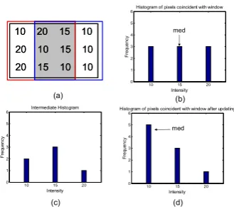
Figure 1 - Illustration of the histogram method used to calculate the median filter. (a) Arbitrary pixel values coincident with a 3x3 win-dow before (red) and after translation (blue). Shaded area - pixels that do not change as window is translated. (b) Histogram of pixels in red window, median = 15. (c) Histogram of pixels that remain in the window after those leaving it have been subtracted. (d) Histo-gram with new values in blue window added, new median = 10.
from the sorted values in this histogram in order to calculate the output of an erosion/dilation respectively at each image pixel. However, instead of generating a new histogram for each translation of the window in the image, the histogram is simply updated by removing the values that exit the window and adding those that enter it as it is translated from pixel, p, to its neighbour. Updating the histogram is achieved by dec-rementing the count in the bins that correspond to the values exiting the window and incrementing the count in the bins corresponding to the values entering it. The min/max value is easily located using this technique since the pixels are al-ready sorted in the histogram.
The authors point out in [1], that it is not always neces-sary to consult the histogram when searching for the maxi-mum or minimaxi-mum rank. In the case of erosion (similarly for dilation) it is only required to search for a new minimum if a value entering the window during translation is lower than the current minimum, or if the count in the histogram bin corresponding to the current minimum reaches zero. For this reason, the authors keep a record of the minimum value which is read for each translation of the window. A new minimum is only sought if one of the previous mentioned situations occurs.
L
B
E
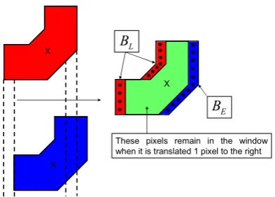
B
These pixels remain in the window when it is translated 1 pixel to the right X
X
[image:3.595.70.267.67.208.2]X
Figure 2 - Illustration of the critical points in the window. (Top) red window centred at (p). (Bottom) Blue window – red window trans-lated 1 pixel right centred at point (p+1). (Right) Critical points of the window (red = BL and blue = BE) and the points that remain in
the window (green) following a single pixel translation to the right.
(higher values within the histogram) of the current median to find the new one.
We demonstrate in Figure 1, the property of the overlap-ping window that is exploited to efficiently update the histo-gram and show by example how to calculate the value of the median using a 3x3 square window. It is more appropriate to demonstrate the calculation of the median rather than erosion or dilation since it facilitates the explanation of our extension of this operator such that we can calculate the outputs of any rank order filter.
Since the shape of a structuring element is extremely important for morphological operations, Van Droogenbroeck and Talbot [1], have extended the method proposed Huang et al. in [3] such that it is possible to compute fast erosions and dilations with any arbitrary window. Take for example the square window used in Figure 1. The only pixels which need to be updated in the histogram are those that are not included in the intersection (shown in grey region of window in Figure 1) of the window and its translation as it moves from one pixel to its neighbour. This concept is further illustrated in Figure 2 where the pixels leaving the window are denoted BL and those entering it are denoted BE. These points are called the “critical points” in [1] and may be computed for any win-dow, initially centred at some point p, using,
BL=B p( ) \
(
B p( )∩B p( +1))
(1)and BE=B p( +1) \
(
B p( )∩B p( +1))
(2)Given (1) and (2) it is possible to compute the critical points for any arbitrarily shaped window and store these in memory. For each translation of the arbitrary window, we remove from the histogram the value of those pixels which coincide with the points BLand add to the histogram the val-ues in the image that coincide with the points of BE.
By combining the techniques demonstrated in Figures 1 and 2, it is possible to extend the methods described previ-ously such that we can compute the output of any rank order filter defined by any arbitrarily shaped window. By using the method of computing the critical points of the window and using these to update the histogram, we can then search for
any rank,
1
≤ ≤
k
n
, using the method described for calcu-lating the median filter as demonstrated in Figure 1. That is, by generating a histogram of the image pixels coincident with the window and updating this histogram with the pixels coincident with the critical points as the window moves, we can exploit the redundancy associated with re-sorting these values. Then, by keeping a count of the number of grey lev-els that are lower than the intensity of the pixel in any rank k, we can quickly compute the output of any rank order filter defined by any arbitrary window B.This can be further generalised if the rank is specified as a percentage, where we would search for the P % rank, al-lowing the rank to be specified independently of the size and shape of the window. Regardless of the size or shape of the window it is possible to identify the kth rank using,
floor ( ) .
100
P
k= ×Card B
(3)
Using (3) it is then possible to compute the output of any rank order filter where for example a dilation would be im-plemented when P=100%. Specifying the rank in this way is particularly useful when implementing the POHMT as de-scribed in Section 3.
3. A PERCENTAGE OCCUPANCY HIT-OR-MISS
TRANSFORM IMPLEMENTED USING RANK
ORDER FILTERS
We demonstrate here, the benefits of extending the method proposed in [1] to the more general case of computing rank order filters by using our extension described in Section 2 to implement a fast POHMT. The POHMT is a recent exten-sion of the well known morphological HMT [4] which re-laxes the fitting criteria of the structuring elements (SEs) such that it is robust when image data is noisy or otherwise distorted. We provide a brief description of the POHMT here, where the interested reader is referred to [6] for a fuller explanation.
The HMT of a binary image X is the intersection of an erosion of X and an erosion of the complement of X by a complementary pair of SEs BFG and BBG respectively where
X, BFG and BBG are sets in 2D space,
E
=
ℤ
2. BFG and BBG are defined relative to a common origin in E where the composite SE B=BFG∪BBG andBFG∩BBG= ∅. That is,
{
}
( ) | ( ) , ( ) c ,
B FG x BG x
HMT X = x E B∈ ⊆X B ⊆X
where
( ) {
|}
x
B = b+x b∈B . A feature is detected by the HMT
if there is at least one point
x
∈
E
such that the foreground SE (BFG)x is included in X whilst the background SE (BBG)x is simultaneously included in its complement, c \X =E X, see [4]. To remain consistent with the literature, we define the notation used here. Let E represent a two dimensional digital space ( 2
E=ℤ ) and E
T be the set of all grey level functions from a subspace of E to T where T= ∪ +∞ −∞ℝ
{
,}
respect to the order “
≤
”. LetI∈TE, denote a greyscaleim-age, andB∈Edenote a flat SE.
The POHMT generalises the HMT by allowing partial fitting of a composite SE such that objects of interest can be detected in an image despite the presence of noise. Instead of using traditional erosions and dilations which require a perfect match between image features and the SEs, the POHMT considers the extent to which a composite SE, B, “fits” the image as it is raised through all grey levels,
t
∈
T
, when its origin is coincident with a pointx
∈
E
,∀ ∈
x
E
. A pointx
∈
E
is marked in the output of the POHMT if - when the origin of the SE is coincident withx
∈
E
- P %, (where Pis set prior to running the POHMT using a design tool that was introduced in [6]) of the points BFG∈Bare beneath or at
the same level as the signal, while simultaneously, P % of the points in BBG∈Bare strictly above the signal. If, when the origin of B is coincident with a point
x
∈
E
, there is at least one levelt
∈
T
for which this condition is satisfied, we deem that the composite SE is P % occupied in the image and this point is marked in the output of the transform. We may calculate the extent to which BFG and BBG are occupiedx
E
∀ ∈
and∀ ∈
t
T
, using,(
)
{
}
(
)
,
|
100
x t
FG FG FG FG
FG
Card b B I x b t PO
Card B
∈ + ≥
= ×
(4)
and
{
(
)
}
(
)
,
|
100
x t
BG BG BG BG
BG
Card b B I x b t
PO
Card B
∈ + <
= ×
(5)
The output of the POHMT may then be calculated by substituting (4) and (5) into,
[ ]
{
, ,}
2 -1 if max min ,
( ) .
0 otherwise
x t x t FG BG
n
FG BG t T
B B B
PO PO P
POHMT x ∈
∈
≥
=
∪
(6)
A direct implementation of the POHMT which processes the image in a single pass can be realised using (4), (5) and (6). Ultimately, the POHMT relaxes the strict conditions of the standard HMT by allowing the partial fitting of SEs where the extent to which the SEs fit a feature in the image may be measured using (4) and (5). A point
x
∈
E
is then marked in the output of the transform if ∃ ∈t Tsuch that P %of BFG fits the feature while P % of BBG fits its background. A common technique that can be used to relax the strictness of morphological operators is to implement more general rank order filters in place of traditional erosions and dilations [4], [6]. Indeed, an equivalent and more efficient implementation of the POHMT can be achieved using the fast rank order filters described in Section 2. Instead of calcu-lating POFG and POBG using (4) and (5) and subsequently the output of the POHMT using (6)
∀ ∈
x
E
and∀ ∈
t
T
, it is equivalent to implement this transform using,[ ] ,100 ,
2 -1 if ( ) ( ) ( ) ( )
( ) .
0 otherwise
FG P BG P FG BG
n
B B
B B B
I x I x
POHMT x ζ − ζ
∈
>
=
∪
(7)
It is clear from (7) that the POHMT may be calculated using rank order filters where the parameter P in (6) may be used to set the rank k for the filter. When implementing the POHMT in this way, we look for places in an image where the intensity in rank (100 – P) is greater for the elements of
BFG than the intensity in rank P for the elements of BBG. The output of the POHMT contains marker pixels for all
x
∈
E
that are coincident with the origin of the SE when this condition is satisfied.We give an example here of how this may be imple-mented. Say we determine for a particular image set, that P
should equal 75% for successful detection of the features that we wish to locate in a noisy image. We can implement the POHMT using rank order filters such that the image pixel that is coincident with the origin of B is marked in the output if the rank corresponding to (100 - 75)% of BFG is at an intensity level greater than the level contained in the rank corresponding to 75% in BBG. This is consistent with the definition of the POHMT as given in (6).
4. EXPERIMENTAL RESULTS
We have implemented the technique described in Section 2 to measure the execution time of our generalised rank order filters. In this section, we compare the speed of our C rou-tine with an optimised Matlab function which calculates the output of rank order filters using techniques described in [3] and [7]. Further, to demonstrate the usefulness of this im-plementation, we draw a comparison between the accuracy and efficiency of a fast POHMT (implemented using the rank order filters described here) with a similar technique that is proposed in [8], which makes the HMT more robust in the presence of noise. We show that our method achieves the same results when processing the image data presented in [8] but in a fraction of the time that is reported there.
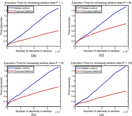
We have measured the execution time of our routine when processing a noisy 512 x 512, 8 bit, greyscale image using an arbitrary window which increases in size. The num-ber of elements in the window ranges from 289 points to 38809 points. We have computed the output of four rank order filters where P = 1, P = 30, P = 50 and P = 100 and have compared the execution time of our implementation and the optimised Matlab routine for each window of increasing size. The results of the comparison for each rank order filter are shown in Figure 3. By reference of Figure 3, it is clear that for all four rank order filters, and for all window sizes, our implementation always outperforms the competing tech-nique by a factor of around 2.
(a) (c)
(b) (d)
0 1 2 3 4
x 104 0
0.2 0.4 0.6 0.8 1 1.2 1.4 1.6
Number of elements in window
T
im
e
(
s
e
c
o
n
d
s
)
Execution Time for increasing window when P = 1
Matlab method Proposed Method
0 1 2 3 4
x 104 0
0.2 0.4 0.6 0.8 1 1.2 1.4 1.6
Number of elements in window
T
im
e
(
s
e
c
o
n
d
s
)
Execution Time for increasing window when P = 50
Matlab method Proposed Method
0 1 2 3 4
x 104 0
0.2 0.4 0.6 0.8 1 1.2 1.4 1.6
Number of elements in window
T
im
e
(
s
e
c
o
n
d
s
)
Execution Time for increasing window when P = 30
Matlab method Proposed Method
0 1 2 3 4
x 104 0
0.2 0.4 0.6 0.8 1 1.2 1.4 1.6
Number of elements in window
T
im
e
(
s
e
c
o
n
d
s
)
Execution Time for increasing window when P = 100
[image:5.595.335.517.67.271.2]Matlab method Proposed Method
Figure 3 - Speed comparison of our fast rank order filters with opti-mised Matlab routine for increasing window size. (a) Minimum filter, P = 1 (b) 30% filter, P = 30 (c) median filter, P = 50 (d) Maximum filter, P = 100.
images. The authors state that an optimised implementation (using heuristic techniques) of their routine takes on average 2 minutes to process one image.
An example of two of these images is shown in Figure 4(a). Clearly, the data is extremely noisy and there are a number of features in the image, in addition the LSB, which we do not wish to detect. We show in Figure 4(b) the results that we achieve when processing this image using the fast POHMT. Note that in Figure 4(b) we have performed open-ing by reconstruction usopen-ing the original image and the marker image produced by the POHMT purely for visualisation of the result. Clearly, the only feature that has been marked in the output of the transform is the LSB. Further, the average time taken to process one image using our method is 15 sec-onds which is a significant improvement on the 2 minutes reported in [8].
5. CONCLUSIONS
We have presented here, a fast algorithm for computing the output of any rank order filter within any arbitrary window. Our technique is a more general version of the method pre-sented in [1] that can be used to compute the output of any rank order filter and is not limited to special cases such as erosion and dilation. In addition to this extension, we pro-vide a mathematical formulation which is missing in [1] that can be used to calculate the so called critical points of the window that must be used when updating the histogram to avoid redundant computation.
We have compared the efficiency of our rank order fil-ters with an optimised Matlab routine for calculating the same. In all cases our method is faster and executes in around half of the time taken by the competing technique. Further, we have shown that by using our fast rank order filters to implement a fast POHMT, we obtain similar results to those presented in [8], in a fraction of the time that is quoted there.
[image:5.595.51.284.69.273.2](b) (a)
Figure 4 - Example of the fast POHMT detecting features of interest in very noisy data.. (a) Source images containing LSB and other features. (b) Output of the fast POHMT followed by an opening by reconstruction.
While the application of our more general algorithm for calculating the output of arbitrarily shaped rank order filters has been restricted to a fast implementation of the POHMT it is possible to use this technique in a number of applications. In fact, any image processing pipeline which uses median filters, morphological operations or more general rank filters to reduce noise or to achieve some other result could see a significant reduction in processing time by implementing these stages using the method proposed here.
REFERENCES
[1] M. Van Droogenbroeck, H. Talbot, “Fast computation of mor-phological operations with arbitrary structuring elements,” J. Pat-tern Recognition Lett., vol. 17, no. 14, pp. 1451-1460, 1996.
[2] I. Pitas and A. N. Venetsanopoulos, "Order statistics in digital image processing", Proc. IEEE, vol. 80, no. 12, pp. 1893 - 1921, 1992.
[3] T.S. Huang, G.J. Yang, and G.Y. Tang, “A fast two dimensional median filtering algorithm,” IEEE Trans. Acoustics, Speech and Signal Processing, vol 27, no. 1, pp. 13-18, Feb 1979.
[4] P. Soille, Morphological Image Analysis: Principles and Appli-cations, New York: Springer, 2003.
[5] E. Urbach and M.H.F Wilkinson, “Efficient 2-D Grayscale Mor-phological Transforms with Arbitrary Flat Structuring Elements”,
IEEE Trans. Image Processing, Vol. 17, No.1, Jan. 2008
[6] P. Murray and S. Marshall, “A New Design Tool for Feature Extraction in Noisy Images based on grayscale Hit-or-Miss Trans-forms”, IEEE Trans. Image Processing, doi: 10.1109/TIP.2010.2103952
[7] Haralick, Robert M., and Linda G. Shapiro, Computer and Robot Vision, Volume I, Addison-Wesley, 1992.
[8] B. Perret, S.Lefèvre, Ch.Collet, “A robust hit-or-miss transform for template matching applied to very noisy astronomical images,”