City, University of London Institutional Repository
Citation: Comley, R.A. (1978). Portable computers for real-time signal processing: EEG analysis as a case study. (Submitted Doctoral thesis, City University, London)
This is the published version of the paper.
This version of the publication may differ from the final published version.
Permanent repository link: http://openaccess.city.ac.uk/18587/
Link to published version:
Copyright and reuse: City Research Online aims to make research outputs of City, University of London available to a wider audience. Copyright and Moral Rights remain with the author(s) and/or copyright holders. URLs from City Research Online may be freely distributed and linked to.
City Research Online: http://openaccess.city.ac.uk/ [email protected]
PORTABLE COMPUTERS FOR REAL-TIME SIGNAL PROCESSING: EEG ANALYSIS
AS A CASE STUDY (VOLUME I)
R.A.COMLEY
Thesis presented for the degree of Docto= of Philosophy
ABSTRACT
Recent advances in both digital hardware and digital signal theory have led to a rapid expansion in the importance and application of computer-aided measurement (CAM) techniques. Of these advances, the emergence of cheap microprocessor
technology of sufficient processing power and speed to support some of the real-time signal-processing tasks encountered in CAM, is probably the single most important factor.
The Roving Slave Processor (RSP) represents a novel extension to the field of CAM. The RSP is a basic hardware unit comprising, in its simplest form, a central processor, a memory system and a means' of input-output. By the use of a microprocessor, it is possible to reduce the size of the complete system to very small dimensions, i.e. to construct a portable computer.
The unit is wholly dependent upon a master computer for the provision of all fundamental peripherals (e.g.
teletype, reader-punch, etc.) and for all program preparation. To provide these facilities, a special purpose interface has been constructed. The RSP is, however, capable of disconnected operation and this is shown to lead to a very efficient and economical means by which to perform CAM operations.
The design and development of two prototypes is described with particular attention being given to the
choice of processor, the storage system and the link to the rnaster computer. Some consideration has also been given to
the problem of how the RSPs should be programmed and a scheme based on a high-level calling system is detailed. Problems of reliability, both hardware and software, are also discussed.
An application of the RSP technique in the very
with particular attention given to the development of an automatic spike detector algorithm. The occurrence of spikes
in the EEG signal is of particular clinical significance as it is indicative of the onset of an epileptic attack. Sharp-waves, slow-waves and all other abnormal behaviour have been
omitted from this study.
A system, based on a filtered, first-order difference of the EEG signal has been developed and is described. Very-encouraging results have been obtained, with a 95% success rate for the abnormal spikes occurring in a series of test records.
1. 2. 3.
4.
5. 6. CONTENTS Abstract Contents Introduction ReviewThe Roving Slave Processor Concept
Practical Realization of the Roving Slave
Page 1. iii 1 4 11
Processor 19 4.1 4.2 4.3
4.4
4.5 4.6 4. 7 4.8 IntroductionChoice of Processor
Interface to Master Computer Memory System
Input - Output Considerations Power Supply Considerations The Software System
Reliability Nature of the Problem
Signal Processing Considerations
6.1 Mathematical Representation
20 21 35 39 49 52 57 67 70 98 101
6.2 Input - Output Considerations 104
6.2.1 The Sampling Process 105
6.2.1.1 Time Domain Sampling 106
6.2.1.2 Frequency Domain Sampling 107
6.2.2 The z-transform 108
6.2.3 Aliasing 110
6.2.4 Quantization 111
6.3 Effect of Errors on Proposed
Signal-Processing Operations 114 6.3.1
6.3.2
6.3.3
Register Length
Limit-Cycle Behaviour
Para~eter Quantization
118
120
7.
8.
6.4 Recursion Noise
Experimental Method and Results 7.1 Differentiation
7.2 7.3 7.4 7.5
Choice of Filter Filter Design
Practical Implementation
EEG Results
7.5.1 Artifact Rejection 7.6 Concluding Remarks
Discussion and Suggestions for Further Work 8.1
8.2
Discussion
Suggestions for Further Work
Page 128 130 131 137 141 146 154 165 169 170
9. Conclusions
171 176 182 185 187 188 189 10. Acknowledgements
11. Appendices
A. Publications
i) The Roving Slave Processor ii) Relieving the Real-Time Signal
Processing Load 194 iii) Super-tool: the microprocessor is
revo1utionising induGtry 199 iv) More bits, more power, more precision 203
v) Digital Filter Implementation by means of Slave Processors
B. Memory Technology Review B.l Introduction
B.2 Semiconductor Random Access Memories B.3 Semiconductor Read Only Memories B.4 Semiconductor, Non-Volatile Random
Access Memory B.S Core Memory
B.G Charge-Coupled Devices B. 7 Magnetic Bubble Memory
B.8 Cassette, Cartridge and Disc Stores C. Memory Reliability
D. Program Listings
i) Autocorrelation Program ii) Spike Detector Program
E. Error Calculations for the Second-Order
Page 238
244
250
251
255
Butterworth Filter 261
E.l Introduction 262
E.2 Cut-Off Frequency Error 262
E.3 Amplitude Error 263
The purpose of the work described in this thesis is two-fold. The initial phases are concerned with the
theoretical constraints, design philosophy and development of a portable digital computer system, suitable for real-time signal-processing applications. The latter phases are concerned with the use of these portable computers in the very.demanding field of real-time analysis of1abnormal
electroencephalogram (EEG) signals.
The portable computers, known as Roving Slave Processors (RSPs), are very basic hardware units that depend upon a
master computer for the provision of all basic peripherals. In their simplest form they comprise a central processor, program and data store and a means of input-output. The RSPs receive their programs from the master computer and, once loaded, they may be disconnected and transported to some required site for operation. In this manner they can be made to fill a whole variety of roles by the provision of a
suitable program.
At the commencement of this project, microprocessors of sufficient speed and processing power, suitable for the RSP, were just becoming available. Two prototype devices, based on different microprocessors, have been developed and are described. One of these was eventually chosen as the
vehicle for a study of the feasibility of providing the real-time EEG analysis, chosen as a target processing task. The random, non-stationary nature of the EEG signal make it a very demanding test case for the portable systems and provides a useful guideline as to their signal-processing potential and power.
The EEG case lS of particular interest, in that ever
still much conjecture as to the usefulness of this gross, averaged and distorted signal, as to whether it conveys any meaningful information or is merely an interesting phenomenon and nothing more [2].
Berger, however, was not only the first to demonstrate the EEG phenomenon in man but was also the first to discover that it was abnormal in epilepsey. This, combined with the work of Walter [3] who established that slowly varying voltages arose near the tissue surrounding brain tumours
which could thus be detected via the EEG, gave electroenceph-alography an air of respectability and led to its acceptance as a tool for clinical diagnosis.
In order to test the RSP principle in this field it was desirable to chose one demanding application, so it lS in
the detection of the abnormal activity occurring as a precursor to an epileptic attack that the main use of the RSPs has been directed. This abnormality usually manifests itself as high-frequency activity in the EEG and the eventual aim is to provide a means of detecting this activity as it occurs (i.e. in real-time).
The two main themes of the research are closely related, though this may not at first sight be evident. A major
consideration when the design of the portable computer was embarked upon was the hope that technology would eventually permit the construction of a pocket-size, portable computer, which may be attached to, and conveniently carried by, a
patient. This would permit the continuous monitoring of that patient and provide a means of automatically detecting, for
example, any abnormal activity of the brain under different environmental conditions.
During the past decade computer-aided measurement (CAM) has become a recognizable and well defined branch of applied science. As the name suggests, it involves the use of a
computer to assist in the solution of a measurement problem. It often involves the computer in controlling and performing the whole measurement task.
There are two main reasons for this rapid development to the present level of importance and applicability, one economic and the other technical necessity. The basic
underlying economic factor is that the computer, by confining speciality to software, enables extensive use to be made of its capital intensive hardware; i.e. the hardware can be
effectively reconfigured to perform a whole range of different operationsi
by the provision of a suitable program. This is not generally the case with specialized equipment, which
tends to be designed for one specific application.
The technical necessity behind the rapid developments ~s simply that many of today's measurement problems are not soluble without the processing power offered by a computer.
Major advances made in integrated circuit technology have had a dramatic impact on signal processing techniques and associated hardware, not only in the design, construction and processing pOvler of digital computers but also on such devices as digital-to-analogue (D-A) and analogue-to-digital
(A-D) converters. These items are indispensable in interfacing with the real (time-continuous) world. A recent development which, 'it appears likely, will have a revolutionary effect
on the field of digital signal-processing, and with it CAM ~n general, is the introduction of the first single-chip microprocessors, in particular the more powerful sixteen-bit devices.
A microprocessor incorporates all of the essential
features of the central processing unit (epe) of a conventional
in a single package. These new devices offer a sufficient operating speed, digital wordlength and computational power to make them suitable for many signal-processing applications.
The rapid advances made in integrated circuit technology have led to a considerable reduction in the cost and physical dimensions of digital processors (Fig. 2.1) thus making
them a viable proposition for many applications and has, further, brought them into range of many potential users.
This cost versus power consideration adds considerable weight to the economic factors already discussed.
Accompanying the recent hardware developments, and of equal importance, are rapid advances being made in digital signal-processing techniques and algorithms [4][5]. The most important of these is probably the rediscovery and subsequent development of the fast Fourier transform (FFT) algorit~~s
[6]. Advances made in digital filter theory and techniques have also been responsible for the increasing use of digital rather than analogue equipment for signal processing.
The development of digital techniques has not only brought about the simulation and replacement of analogue techniques, but has also led to entirely new theories and methods which exploit the discrete nature of the data and
have no counterpart in the older theories. The combination of these theories and techniques ,,,ith the processing power of modern computing devices is providing the experimenter with unprecedented signal-processing capabilities.
A brief review of the application of this new found capability to the problem of real-time analyses of the electrical activity of the brain will now be presented.
An enormous amount of effort has been expended in random signal analysis techniques for application to EEG
resulting in many papers on computerized pattern recognition (or feature ext:-,'::ction) schemes [71[R1. Of these~ most ayC'
~.
~---
.
Figure 2.1 The F100L - a complete central processing unit
and are thus of little direct relevance to the current project, except where the algorithms may be modified to produce a
real-time solution. From the papers concerned with real-time EEG analysis, none could be found which utilized a micro-processor as the basic processing element, and so it has been assumed that none exists. Indeed there is very little published work in any branch of signal-processing concerning the use of microprocessors. The papers to be reviewed have-been selected with an emphasis placed on schemes which offer the potential for possible modification and implementation on a microprocessor based system.
Special purpose hardware systems have been built for automatic spike detection (the high-frequency abnormality referred to in Chapter 1) that employ the second derivative and spike width as the criteria for detection (9][lO] • Carrie used a hybrid computer for spike detection working on both
the orignal EEG signal and its second derivative
[11].
A quantitative comparison was made between values from consec-utive EEG waves and a moving average. An output was generated when the ratio of the input sample to the moving averageexceeded a preset limit. Carrie reported that use of the second derivative gave better results than the first derivative.
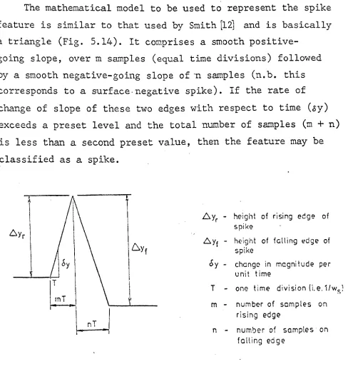
Smith [l2] used a technique of modelling the waveform
to be recognized. The model adopted was a triangle to classify the three essential features of an abnormal
spike:-i) a relatively large and smooth slope followed by a similar slope of opposite polarity
ii) a sharp apex
iii) a definable base of 20 - 80ms.
analysed with this technique, the predominant cause of false alarms being muscle artifact (which'satisfied the spike
model) .
Various methods of performing a direct filtering operation on the original data have been implemented. One such method was that of matched filtering [13]. For this, a non-recursive filter whose pulse response is the required
signal in reverse form is used. Reasonable results can be obtained by the use of this method but it suffers from a
high false alarm and 'miss' rate because many different spike waveforms may occur, each requiring a different matched
filter.
Another approach is the use of a bandpass filter centred around the spike frequency. Stevens et al [14] describe such a system which utilizes a 6 - 10Hz bandpass filter, a slope recognition unit and a voltage trigger. The parameters were preset for each subject on an empirical basis, which appears
to be its major disadvantage. The method was used to carry out an automatic analysis, on recorded data, of spikes occurring in 24hr. epochs. The performance of the system, to quote the authors, ' ... suffered from arbitary errors ... but is likely to be more consistent than intuitive recog-nition by the electroencephalographer' (i.e. the system does not appear to be a very sound means of automatic recognition).
A long term analyser has also been developed by Gergely and Paul [15] which enables a short length of record preceeding and following a spike-and-wave discharge to be recorded.
This leads to a considerable condensation of the data collected during a long term analysis, by removing the
substantial lengths of record between the features of interest. The device operates on all sixteen channels of a conventional EEG recording simultaneously, but trigger levels can be set
Various studies have been conducted involving the fast Fourier transform (FFT) since the orignal work of Grass and Gibbs [16]. These are concerned more with an analysis of the frequency components of the complete waveform rather than for the detection of specific features. As a result they were considered to be an unsuitable method for the purposes
of detecting spike activity. A further consideration against the Fourier methods is that of computational requirements and the effect this would have on the real-time bandwidth of any system using them as a means of analysis.
Any computer installation engaged in computer-aided measurement will almost certainly experience periods of
inefficient usage. The extent of this inefficiency will be directly related to the proportion of time during which the computer performs real-time signal-processing measurements.
This appears to be a contradictory state of affairs, after all if the purpose of the computer is to assist in measurement tasks any increase in this demand should lead, ~
automatically, to an increase in the efficiency of use. However, a closer inspection of a number of typical CAM problems indicates that this assumption may not always be
correct. In general, three distinct phases may be identified:-i) preparation
ii) measurement iii) post mortem.
A consideration of the computational requirements of these phases reveals that phase (ii) is very different in nature from phases (i) and (iii).
The preparation phase is the period during which the measurement problem is analysed and the programs, necessary
for its solution, written and tested. This will normally require the use of many of the system resources, both peripherals and system software.
The measurement phase consists of using the programs
prepared in phase (i) to carry out the prescribed measurement. This will not, in general, require any of the system resources other than the central processing unit (CPU) itself and a
few signal-processing peripherals (e.g. analogue-to-digital and digital-to-analogue converters, real-time clock, etc.). The final phase, post mortem, is an optional phase and the usual activity here lS further analysis of the results
As can be seen, phase (ii) requires none of the system resources required by the other two and it is as a consequence of this difference that the computer system can be put to
very inefficient use. The situation is further aggravated by the fact that much, or all, of the measurement phase may
involve real-time processing, usually with full occupancy I
of the CPU.
It is worthwhile defining the term real-time, at this ~
stage, as it has been the author's experience that the term suffers from a 'Humpty Dumpty' type of definition in that it means whatever the user wants it to mean! By real-time, the author is implying that the interaction between input and output of the computer is such that a minimum processing speed exists, below which there is an essent i.al bn;akdown in the intended sequence of operation.
This should not be confused with on-line for which
there is usually no such lower limit, other than the artifice of time-out circuits, which may be included on some periph-erals, and the patience of ,the user. Real-time ~s a special class o~ on-line operation. All three phases of the typical CAM exercise discussed involve on-line processing but only phase (ii) will involve any real-time demands. Phases (i) and (iii) may be conducted quite conveniently under multi-user, time-sharing conditions, but the processes involved
in phase (ii) may be so time dependent that the entire
processing power of the CPU must be devoted to the execution of the measurement program. As a result, all of the expensive peripherals will stand idle until the measurement is
comp-leted. Obviously, phase (ii) makes very inefficient use of the computer installation and as the real-time load ~s increased so the efficiency of use will decrease.
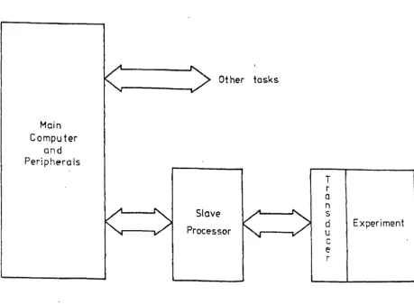
micro-processor system. The normal relationship between the pre-processor and the main pre-processor is some form of hierarchy with the main processor acting as master and the pre-processor
its slave. The connection of the on-line experiment is now modified from the simple layout of Figure 3.1 to that sho~~
in Figure 3.2. The slave processor can now be delegated various operations concerned with the real-time measurement
task only requesting attention from the main computer when, absolutely necessary.
This can ease the load on the main processor considerably, leaving it free to perform other tasks betw€en interruptions from the experiment. The number of interruptions received by the main processor during the course of a measurement will depend upon the nature of the measurement and the
computational power of the slave processor. If a minicomputer is used it should be able to act in almost total autonomy, once loaded with its program from the main processor. An interrupt need only be requested upon completion of the assigned task or if, for example, a block of data is to be
transferred to the main backing store (e.g. disc). In contrast, if the slave falls in the special hardware category it may
be very basic and will demand attention from the main
processor for all but very simple operations; e.g. the slave may be a simple level detector which causes an interrupt to
the main processor every time the input rises above a pre-defined threshold level. The main computer would then take over and perform the required analysis on the input waveform returning control back to the slave upon completion, to
await the next interrupt. The microprocessor based solution falls between these two extremes and its power is a direct function of the power and complexity of the microprocessor and associated system.
T
Main r
a Computer
:>
ns Experiment
and
~
dPeripherals u
c e r
Figure 3.1 Connection of an on-line experiment.
Main Computer
and Peripherals
Other tasks
Slave
Processor
T
r a n s
d Experiment
u c e r
[image:22.596.110.541.73.408.2] [image:22.596.87.547.460.798.2]important of these being the Pulse Height Analyser
(17]
and Transient Recorder(18].
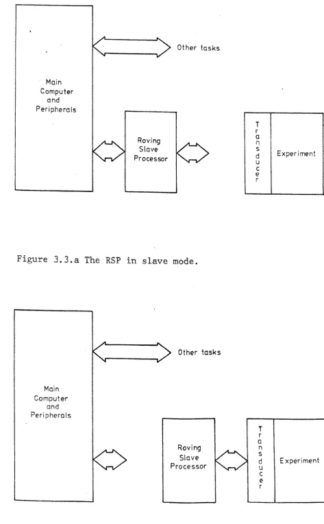
It was during this work that another problem was becoming more prominent, and that was thephysical immobility of the computer installation. There was a real need to be able to transport the power of the main computer to remote sites, and it was from this need that the idea of the Roving Slave Processor arose [19][20][21][22]. In this, the hierarchical system already outlined is taken a . stage further and the slave processor is made detachable. It is then free to be taken to the object under test rather than vice-versa, as is the normal case (see Figs. 3.3.a and 3.3.b).
The RSP is dependent upon the main computer for all program preparation and ?rovision of peripherals, as is any pre-processing device, but unlike the others once it has been loaded with a suitable program it Ls r::.a~)abI e of disconnected operation.
Several important advantages accrue from an approach of this type, besides those already mentioned; a few of the more important \vill be considered briefly.
Firstly, numerous RSPs may be serviced via a single link to the master, instead of each pre-processor requiring its o~m individual link which can involve important economic consequences.
Individual users may have exclusive use of an RSP for considerable periods which can be of great importance as
some measurements can involve many hours, or even days, of continuous monitoring.
Certain important peripherals can be given a roving commission, e.g. the Transient Recorder [23] .
Finally, and probably most important of all, is the
fact that
~heRSP is,
lnessence, a portable, software
Main Computer
and Peripherals
Other tasks
Roving Slave Processor
Figure 3.3.a The RSP in slave mode.
Main Computer
and Peripherals
Other tasks
Roving Slave Processor
T r a n s d u c e r
T
r
a n
s d
u
c e
r
Exper i ment
Experiment
[image:24.589.65.539.22.787.2]instruments to perform a variety of measurement and control operations.
Clearly, the hardware unit devised to fulfil the role of the RSP must be of sufficient computational power to
facilitate its useful application to a variety of measurement problems and also be of suitable dimensions to permit easy transportation, i.e. it must be portable rather than trans-portable. Ideally, the final version will be a pocket-sized device.
Of equal importance to the hardware considerations is the soft'\vare system necessary to exploit the RSPs. With
the availability of these basic hardware units it is possible to describe an instrument as a concatenation of standard
software blocks [24]. Ultimately, the usefulness and applic-ability of the RSP technique will depend upon the organization of the software system and the ease with which it may be
4.1 Introduction
The design constraints laid down for the RSP in t~e
previous chapter were that it C.ust be of sufficient comp-utational power to permit its useful application to many
signal-processing and cont~ol proble~s and that the complete system must be portable, easy to use (interface) and to
program. The practical implications of these constraints will be considered in this chapter.
,
It is proposed tr~t a very basic hardware unit comprising, in its simplest form, a central processor (microprocessor), a program and data store and a means of input-output, fonn the basis of the RSP (Fig. 4.1). A configuration of this type offers the potential of producing a miniature device. Special hardware units may be added to the basic processing unit, as required, for specific applications (e.g. real-time
clock, hard\vare multiply-divide, etc.). The basic unit, however, should be capable of performing many of its processing tasks alone, without the aid of these special add-on hardware units.
Program and
Data store
'</
. - ':
._._---~rocessor
Input - Output
C hanriel
!
'"
.--' 7'
,
.
Figure
4.1 The basic RSPThree prototype stages were planned, the first to be a large rack-mounted system housed in a mobile unit. This system is the one used in the present research to evaluate the applicability and potential power of the RSP concept. The second prototype is to be a portable device of similar proportions to a modern oscilloscope and a final stage
involves the construction of a miniature version, of about the size of a pocket calculator.
4.2 Choice of Processor
This is the most fundamental decision to be made, an incorrect decision at this stage could invalidate the whole project. The two major considerations are the choice between multichip (i.e. bit-slices) or single board microprocessors
and single chip devices, and the wordlength required for the envisaged applications.
The bit-slice approach appears attractive on first inspection since the wordlength can be tailored to suit the application as can the instruction set via microprogramming. Bit-slice and single board systems must, however, be rejected on size and weight grounds. Not only are the circuits involved bulky, but large supplies are also required to power them. Also, microprogramming is very expensive in man-hours, \\'hich would have posed serious problems.
These constraints effectively limit the choice of microprocessor to a single chip device. Further, the processor eventually chosen must be of sufficient
co~put-ational power to fulfil the processing requirements outlined earlier (Chap. 2), on its own. If it becomes necessary to resort to a multiprocessor design to achieve the desired goals then a bit-slice or single board system may as well have been opted for from the outset, since the two sysl\:'T:~S
will be of similar dimensions and will both involve s: i 'ar
As an example, a dual processor design based on the
FIOOL
microprocessor is compared with the single board'Miproc t. system, in Figure 4.2. The elements shown in the
dual
FIOO
system correspond to the processing unit repre-sented by the single board Miproc. A hardwaremultiply-divide chip has been included since Miproc has this facility and the memory and interface for th~ second processor must also be included since they are additions, necessarily
introduced by the second processor. In both cases, the main memory and other system peripherals have been omitted and
so, as far as possible, two like systems are being compared. As can be seen, the dual processor system does not
appear very attractive when considered as a complete processing unit with all of its additional circuitry. With other
single chip processors the situation would be somewhat worse, since the
FIOO
is geared to multiprocessor configurations. Not only is the multiprocessor system slower than a comparablesingle board system, of approximately the same board area and with similar power supply requirements, but it is also far more complicated to program. One of the design criteria for the RSP is that it must be easy to use and understand so that persons whose expertise does not lie in the comp-uting field may utilize them (see Chap.3). The concept of
a multiprocessor approach was favoured at the commence~ent
of the proj ect [22J and is still the subj ect of much research, the main aim being to relieve possible input-output bottle-necks.
The original intention was to produce a dual processor system with the secondary processor responsible for all input-output operations. As has been shmm by Figure 4.2,
this is not such an attractive system as was first anticipate1. The dual processor approach represents an elegant conceptual
system but it is now the author's opinion that it is
Power Requirompnts
+5v at 3A
Basic instruction
L
ex<?cU1ion t iiTle\' ~350ns (zero acces.s 1
_ L . . rl'12mor
FiOO
k
235~
B u f f e r B u f f e r '
-Multiply I
Divide
C
c
0 n t r 0 I ~ r----B u f f e r
F100 I
-8 u f f e r
Buffer Buffer
B uf fer Buffer
r ' '
-Cont rot
Buffer Buffer
Interface I
~---1-K-'X-1-5-"-DI~
Nerr,ory I
I ! o n t r o I
Primary Bus
Power Requir('mer,t s
2 x F100 8[,0 rnA
10xBuffers 1.200A
3xControl 255mA
1 x Mutt.! Div. 100 rnA
16x Memories 90GmA
1 x Interface
(::: 10 x 'LSpacks) 50mA
Total 3.3/.5 A
at +5v
Secondary Bus
Basic 'Instruction execut ion time
-~)Js(for5M~z
2
ctock and zero access rnemory 1
Figure 4.2 Gomparison of sixteen-bit single-board and dual
[image:30.591.84.554.19.793.2]version.
It is possible to reduce the total power requirement of the dual processor system given 1_n Figure 4.2 by the substitution of specially constructed circuits to replace some of the interface sets (e.g. the memory interface).
This, suprisingly, does not involve any appreciable increase in the physical dimensions of the interface and can reduce power consumption quite appreciably. The major problem of ~
this approach, however, is the considerable amount of
valuable research time which must be spent in development. These comments do not, however, rule out the use of secondary microprocessors as part of special processing units (SPUs), or peripheral control units (PCUs), the
optional add-on hardware units discussed at the beginning of this chapter. Indeed, a microprocessor based solution will often represent the optimum choice for an SPU or PCU
application. It should be re-emphasized, though, that these are optional add-on units, extra to the basic RSP.
Before any comparisons are made between the available single chip microprocessors, it is necessary to determine the wordlength requirement. This will be specified by the most demanding application envisaged for the RSP. These will arise in real-time signal-processing applications. Of the
real-time processing tasks, digital filtering is likely to present one of the most demanding computational problems, and was therefore used as a 'benchmark' to help determine wordlength requirements. The theoretical constraints imposed
during the design phase have been subsequently borne-out by practical assessments on prototype devices ~5J .
discrete levels used to descibe the original waveform (see
Chap.6). The difference, in amplitude, between adjacent
quantization levels, and hence the number of points used
to describe a given input level, is related to the number
of binary digits available to describe each level. The number
of bits used has a direct effect on the accuracy to which a
given input level can be defined:-number
of bits 4 8 10 12 14 16 number of levels
16 256 1024 4096 16384 65536 % error 6.25 0.39 0.098 0.024 0.006 0.0015
Clearly, ten bits would appear to be the optimum number
of bits to use as it provides an accuracy of 1 part in 103 ,
which should be suitable for most instrumentational
requ-irements. However, eight-bit devices (A-D converters) are
mo~e readily available and these offer an accuracy of 4
parts in 103 , which was considered adequate for the present
applications (see Chap.6).
At this stage eight or sixteen-bit microprocessors
appear equally acceptable. Problems start to occur for
'eight-bit devices as soon as any processing is performed
on the input data, however. For any input above half
full-scale (i.e. bit 7 set) ambiguities arise over the sign of
the data and hence the sign of any calculated results. A
reduction in the A-D conversion accuracy to seven bits
giving an accuracy of 8 parts in 103 (approx. 1%) was
considered unacceptable. As a result, the user will be
immediately forced to double-length working with its
associated increase in co~putational load and programming
effort. Neither of these overheads are compatible with the
RSP concept. The effect of the increased program length
will be to more than halve the operating speed of the
system, thereby reducing the real-time "bandwidth.
It can be argued that some eight-bit microprocessors operate at more than twice the speed of current sixteen-bit devices and so double-length working would impose no bandwidth penalty. The faster eight-bit devices, however, will impose a greater load on the power supply than the
sixteen-bit machine they would replace. This need not necessarily be only as a function of the processor itself but due to such factors as the requirement for faster memory systems, with an associated increase in power
consumption.
From the point of view of increased programming effort, double-length working demands a comprehensive understanding and programming knowledge on the part of the user, which has the effect of making the RSP a difficult device to use.
The programming area is where the sixteen-bit micro-processors have an undisputable advantage over the eight-bit machines. The range and flexibility of instructions facilitated by a sixteen-bit wide instruction field is vastly superior to anything which can be supported by an
eight-bit field.
Finally, some operations involve the use of fixed constants which are used in calculations, e.g. the
coeff-icients required in a digital filter calculation. The range these coefficients may take is again governed by the number of binary digits available for their quantized representation. For this purpose even sixteen-bits is none too generous,
offering only ±32,768 levels (i.e. 0.003%). Further, when these constants, or indeed any quantities, are used in calculations, the number of bits required to represent the
results will, in general, be more than was required to describe the original values (e.g. intermediate results in
are often inadequate. The effects of finite wordlengths are considered further in Chapter 6.
Following the choice of a sixt~en-bit processor a review of those available was made. Three main contenders were identified, each offering a specific advantage over
the other two [26] • The three chosen were the Ferranti FIOOL, General Instrument Corporation CP1600 and Texas Instruments TMS9900.
The FIOOL has already been mentioned and is attractive as it has been designed to a military specification and has come from a computer manufacturer unlike the other two,
which come from semiconductor 'manufacturers. This background manifests itself in subtle ways in the architecture, input-output structure and instruction set.
The CP1600 is attractive from the point of view that it was designed primarily for real-time applications. It is not only a very powerful single chip microprocessor but is also easy to understand and use. In addition to the normal mnemonic assembly language, a 'Super Assembly Language' is
also available (see sect.' 4.7) which provides a very powerful, yet easy to use, real-time programming language. Also worthy
of special note is the inclusion of two interrupt inputs, one maskable in software and the other not, and a group of four outputs and one input which may be demultiplexed to provide a powerful polling system comprising sixteen possible inputs.
The TMS9900 is probably the most powerful of the three single chip microprocessors considered. The inclusion of a hardware multiply-divide facility in the circuit which, even if only for unsigned operations, gives the device a great advantage in terms of processing power. The major
disadvantage of the TMS9900 is the large number of additional packages it requires for a minimal system configuration.
Any advantage offered to the
RSP
by the hardwaredivide facility is more than offset by this latter requirement. The processor should not, however, be considered in
isolation, special purpose interface chips must also be considered. These are not necessarily for incorporation into the RSP but may prove very useful for peripherals to be attached to the RSP. Special purpose interface chips make the task of interfacing user peripherals to the system very simple and hence make the RSP easier to use.
The F100 is well supported from this point of view, having a three-chip 'interface-set' which can be made to
operate in one of five modes:-i) peripheral mode
ii) store mode
iii) special processor unit (SPU) mode iv) bus extension mode
v) buffer mode
Not all of these modes are usable in a real-time system, for example when one is employed as a store interface a minimum delay of 775ns for a read and l~s for a write
operation is introduced for. current 5MHz devices. This timing overhead, added to the access time of the memory devices makes the memory cycle prohibitively long for any real-time system. Further, the size of the full interface-set, three forty-pin packages, and power requirement of 325rnA virtually exclude their use in any mode within the RSP. However,in their place, the interface-sets can simplify considerably the task of connecting peripherals to the FlOO bus.
The CP1600 is also well supported in terms of special interface chips having two main support chips, the input-output buffer (lOB) and peripheral interface controller
(PIC). These are designed specifically as peripheral interface devices, both housed in forty-pin packages. The lOB is
basically an eight-bit buffer offering two bi-directional,
eight-bit ports to the user. Also included are registers to hold the interrupt vector for the attached peripheral, an error input and associated interrupt vector and timer circuit which may be used to count external events or be controlled by an oscillator.
The PIC device is virtually a microcomputer in its own right and may be delegated tasks from the CP1600. Unfortun-ately this requires that the PIC has an internal program store, which is of the mask-programmable type. This rules out their application to experimental work since, to be economic, they must be manufactured in large quantities
(>1000) to cover the initial masking charges.
The TMS9900, at present, has no special interface
devices and it is left to the user to construct any that may be required. This makes the TMS9900 inconvenient when
peripheral interfacing is involved.
As well as the hardware required for interface, the method of data transfer must also be considered. The FIOO
operates on an asynchronous transfer basis (i.e. transfers are not tied to the system 'clock) whereas the other two use synchronous systems. The asynchronous method offers a
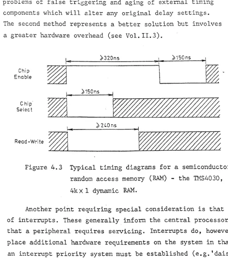
faster overall transfer rate, which is in keeping with real-time considerations, but in general requires a more complex interface involving more hardware than an equivalent synch-ronous system. Further, many peripherals are inherently synchronous in operation and so little speed advantage can be offered by the asynchronous system. Take for example, the commonest peripheral, a memory. The normal sequence for a memory access, shown in Figure 4.3, has strict timing
requirements imposed on the clocking waveforms. With a synchronous system, the system clock can generally be the source of these waveforms. For the asynchronous system, either monos tables or some form of clock and dividing
for high-integrity systems, which the RSP must be, due to
problems of false triggering and aging of external timing
components which will ~lter any original delay settings.
The second method represents a better solution but involves
a greater hardware overhead (see Vol.II.3).
Chip
Enable
Ie!! ),320ns 'PL 1 • J,150ns
~~~I
___~~_15_0_n_s
__~_~1 ~~rT~~~r7~~/7~~77~
Chip
/m3
_ _ _
Select ~
)2l.0ns
1_ ~I
Figure 4.3 Typical timing diagrams for a semiconductor
random access memory (RAM) - the TMS4030,
4k X 1 dynamic RAM.
Another point requiring special consideration is that
of interrupts. These generally inform the central processor
that a peripheral requires servicing. Interrupts do, however,
place additional hardvlare requirements on the system in that
an interrupt priority system must be established (e.g. 'daisy
chain') and any interrupting device must supply the start
address of its service routine to the processor. Wherever
possible, a polling" scheme should be used, which will often
suffice for many applications, although for some, the
interrupt facility will still be required. The polling and
interrupt system offered by the
CP1600
make it ve=y attractivefrom this point of vie\v.
A final point in the choice of processor, is the
provision of internal registers in which intermediate results
may be stored as opposed to main memory locations. The
CP1600
[image:37.598.75.546.50.583.2]has eight internal registers, the F100L only one and the TMS9900 relies entirely on external memory. The argument in favour of the use of memory locations instead of internal registers is that interrupts may be serviced very quickly, since few registers need be saved; the TMS9900 merely
switches to a new group of memory registers in a single operation. The argument in favour of internal registers is that they make the device easier to program.
Another important consideration, in favour of the internal register approach, for the RSP, is one of power consumption. The memory system will draw most power when it is accessed, due to the fact that current must be switched into capacitive loads (see sect.4.4). The situation is
emphasized for many memory devices which may be placed in a low-power standby mode between access operations. For certain devices the standby current can be reduced to a negligible value (pA) e.g. CMOS devices (see sect.4.4 and Appendix B).
Hence, it can be seen that any method of minimizing the number of memory access operations, involved in a g~ven program, will minimize the 'supply drain imposed by the
system. This is an important consideration since the miniature RSPs are to be battery operated and so the average supply
drain is very significant.
An example to demonstrate the effect of internal
registers on the average power drain imposed by the memory, is given in Table 4.1, where the same programming operation performed on the CP1600 and FIOOL are compared. The example
illustrates not only the considerable reduction in the
number of memory accesses but also the program simplification offered by the multiple internal registers. Hence, on both counts, the provision of internal registers must be considered as a very desirable feature of the processor to be used in the RSP.
are suwmarized in Table 4.2. From the'foregoing section and a study of Table 4.2, it would appear that the CP1600
represents the optimum choice for the microprocessor most suited to the RSP application (presently available).
Two prototype systems have, in fact, been constructed, one based on the CP1600 and the other on the F100M, '\vhich is a five board processor, equivalent to the single chip
FIOOL
in all but size and power requirements (Fig.4.4).Table 4.1 Effect of internal registers on number of memory access operations.
Function:- Yn
=
xn+ Yn-I+ Xn-I2 2
FIOOL
LDA
xSRL 1
STO ml
ADD m3
ADD
rn2
STO Y STO
m3
LDA ml STO m2
CPl600
'::MVI
x,RO
SLR RO,l
ADDR
RO,RlADDR R2,Rl
MOVR RO,R2
):< - Double-word instruction FIOOL
9
instr. fetch cycles+ 6 memory cycles
=
15 IT.e~oryaccesses+
=
8 0 8 Comments Load x n value Divide by twoSave result (in location ml) Add Yn-I term
Add Xn-I term
-2-Output result
Store next Yn-I value Fetch next xn-Ivalue
2
Store new Xn-I value
2
Continue
CP1600
instr. f~tch cycles :::emory cycles
[image:39.602.71.548.307.853.2].
.
-
.
..
..
.-
.
-
.
,--
.
.
....
...
...
-I . . . . . I, ..
•
•
•
•
•
W .J> Device FIOOL CP1600 TMS 9900
Basic Total
No. of Basic instrct. Intrn1 No. of Power power
bits instrct. execute regs. clocks Package supp1s. dissip. Document.
time (typ) (typ)
1.9 - 37SmW
16 109 8.8ps 1 1 40 pin +SV
in CPU Poor
, (3S0ns di1 @420mA
+ 1.72SW memory ...
SHHz CPU) in pass transis.
2.4 - +12V @
7 . 2 flS 40 pin 70rnA Very
16 87 basic CPU 8 2 dil
+5v
@900mW
1.6 - 12mA
good
4.8 flS -3V @
'A'
versn. 0.2mA4.7 - +12V @
41.3,us 30mA
(assuming 0 4 64 pin +SV @ 990mW Good
16 72 no wait di1 12SmA
cycles -SV @
for slow 1rnA
.
memory)
Table 4.2 Comparison of three, sixteen-bit, single-chip microprocessors. (
Interface Special support
I
featu.resI
I
Special
Good Processor
facility
Branch external
Good polling
system. Super assmb1r.
Ha ::-d\·;are
Poor mul ti.
-di\-ide
I
4.3 Interface to Master ComEuter
The interface, or link, between the main computer and the RSP is a fundamental component of the overall RSP
philosophy. A great deal of design consideration and
constructional effort has been expended on this part of the project. The first task was to define a design specification
for the link and the functions it was to perform. Basically, the function of the link is to transfer data between the master computer and the RSP, and vice-versa. This data
transfer may take the form of block or single word transfers. Since the final RSPs will have no front-panels a means of controlling start-stop operations from the master computer via the link will also be required.
Three basic approaches were identified, each offering different merits and drawbacks. The three methods
are:-i) a special parallel highway, connected directly into the main computer's bi-directional data highway
ii) modification of an existing channel already available on the main computer (e.g. high-speed teletype channel to give a high-speed serial link) iii) use of a general purpose input-output channel,
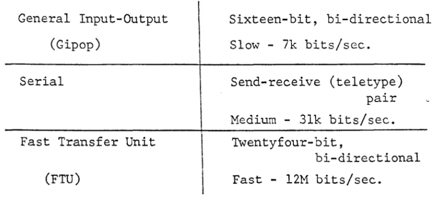
available as an option on most minicomputers. The option based on method (iii) above, has been developed and is, at present, the only link between the master and slave processors, although both of the other methods are being evaluated [27] (28) • The basic features of
an eight-bit microprocessor has been used as the basis of
the system.
General Input-Output
(Gipop)
Serial
Fast Transfer Unit
(FTU)
Sixteen-bit, bi-directional
Slow - 7k bits/sec.
Send-receive (teletype) pair
Medium - 31k bits/sec.
Twentyfour-bit,
bi-directional
Fast - 12M bits/sec.
Table 4.3 Characteristics of Link Methods.
The general input-o~tput (Gipop) channel, although the
poorest choice from the performance point of view, represents
the simplest approach both in terms of design and
construct-ional time and effort. Since the link forms an essential,
but not a major section of the overall RSP development
program, it was decided that, for the purposes of this
research, the Gipop method offered the best solution.
The link system developed is basically a sixteen-bit
parallel, bi-directional data highway to the RSP, constituted
from two sixteen-bit uni-directional highways from the master
computer (Fig.4.5). Data are transferred as a series of direct
memory access operations controlled by an asynchronous
handshake pair plus an additional control line. The control
input serves to latch a four-bit control word into the link
which specifies the type of operation to be performed. The
control word is stable at. the link output before any data
transfer request signals are issued.
At the time of writing, only the prot·otype based on
the FlOOM is interfaced to the link; the CP1600 being, at
present, a more self-contained system lS less dependent upon
[image:43.600.111.554.100.302.2]the master cor,lputer for progro.m preparation and associated activities n A separate hlJffer board ,\\'as constructed to form
the interface bctv7een the FlOOl-'1 data bus and the Gipop link. The design of the buffer was complicated by problems
encountered Iv-ith time-out circuits built into the FIOOM
system, which did not allow sufficient time for data
transfers from the link. As a result, the buffer circuitry became a little more complex than was originally intended.' From Table 4.3, it can be seen that 'vith the link, transfer rates of up to 70Hz are possible. Hence, for a thousand-word program, a loading time of l5sec. will be required.
This may appear excessive, but in practice p:roves more than usable.
I nt
~'---!
16 Mast er
Ccmput er
16
3
Gipop
link
Control
Date 110
'HO:lcshc:-<.\?' Pair
Figure 4.5 General input-output link to the master computer.
Full design and constructional details of both the Gipop link and buffer circuits are given in Volume I I
(Chaps. land 2), together with listings of the control programs required to op'2rate the system. At present the
Disc
Plotter
Main Computer
R.S.P.
Tape Reader
VDU .
'---'~
Teletype Tape Punch
AID Conv. Processor
G 8 DIA
i u Cony.
p f
0 f Real
p e Time Experiment
r
Non-volatile Clock store
Inter-~
face
I
A diagramic representation of the Gipop system in use is "given in Figure 4.6. For data transfers between the master and slave computers, the RSP is plugged into the
Gipop link, as shown, and when ready, may be disconnected and taken to the site of the experiment. A further
consideration arises at this stage, again due to the fact that the final RSP versions are to have no front-panels.
It is essential during program loading to check that . the program has been transferred to the RSP's store correctly. A simple method of performing this check is to read the data,
just written, back from the RSP's store, one word at a time, and compar.e it with the corresponding word in the master computer's store. The comparison process is merely an
exclusive-OR operation; any result other than zero indicates an error and the bit position(s) indicate the location(s)
of the error(s).
The error checking process is, in fact, performing an integrity check on the Gipop link, buffer and RSP memory, as well as checking the transferred data.
It may also be desirable to perform a check on data
read from the RSP to the master computer (e.g. for phase (iii) operations - see Chap.3). In this mode, the initial read and checking operations would be performed in the normal manner, except that now the check word in dispute (i.e. second read from an RSP store location) must also be stored. When an error 1S found, a third read must be performed to establish
which of the previous two readings was in error. It should be noted that the read check cannot identify errors in the Gipop link, buffer or RSP memory; a write-read operation
is the only way in which this check may be performed.
4.4 Memory System
section 4.2. A vast range of memory devices is available from which to fabricate the system, all with different technical
specifications.
The basic requirements of the memory are that it is sixteen-bits wide, since a sixteen-bit processor is to be used, and 4k (4096) words in length. For many applications, a lk (1024) word memory would suffice but it is considered that to make the RSP completely general purpose, a minimum of 4k words is desirable.
It is proposed that the entire memory be of the read-write type, with no predefined distinction made between which portions are to be used for program or data storage.
It is left to the user to define the partitioning of the memory, which means it may be tailored to suit individual applications. A restriction will normally be imposed on the
start address of the program area which is defined by the reset address of the microprocessor employed. Any reset address may be provided for the CP1600 and this will
normally be location zero, but the
FIOOL
is confined to reset to location 2048 or 16384.The use of read-write memory makes the task of programming and re-programming fairly easy, which is an
important consideration for a device like the RSP, which will require frequent program changes. A further requirement
of the memory is that it must be fast in order to maintain the real-time potential of the RSP system. This last require-ment imposes many conflicting design problems since, in general,
as the speed of the memory is increased so the power consump-tion rises.
mains power is removed.
From the non-volatility point of view, core storage would appear attractive, but unfortunately this must be
rejected on the grounds of size and weight. A 4kx16 core memory would not only be bulky, but the power supplies
required to drive it would also have to be large.
A recent development in this area, is the introduction of bubble memories. Like core store, these devices depend upon a magnetic form of data storage. At present, bubble memories are better suited to mass storage systems (see
later), being organized in a 64k or 92kxl configuration with average access times in the order of 4ms. Further, they
impose a fairly heavy load on the power supply during use. Hence, although bubble memories offer a non-volatile storage medium with a high packing density, they are not suitable
for the read-write store of the RSP, in their present form. Two other devices, recently introduced, are also of
some interest. The first of these is the electrically alterable read-only memory (EAROM), which is a programmable read-only memory (PROM) that may be programmed and re-programrned with
the use of an overvoltage input (compared with TTL levels). These devices are far more convenient in use than their ultra-violet erasable counterparts in that they do not need
to be cleared before prograrnming and further, the re-programming may be performed with the chips in circuit
(provided any TTL circuits are protected). Unfortunately, present devices are fairly slow in operation, with typical access times of 1 - 4~s. Their main disadvantage, however,
is that they are only suitable for program storage; it is not a practical proposition to program the EAROMs via the
RSP during program execution. Hence, if EAROMs were used it would be necessary to separate the program and data stores,
A better solution is just becoming available in the form of a non-volatile random access memory (RAM). This is a very new device and still requires some technological improvements before it will be useful for the RSP. Basically, the device comprises two distinct storage areas, one a RAM and the other an EAROM, into which the data held in RAM are copied upon power down. When power is restored the contents of the EAROM are returned to their appropriate RAM locations and the system
is again ready for use. Present devices are organized in a 256x4 bit configuration and although rather slow in operation
(typical access time 1.5~s) they hold great promise for the future.
All of the devices discussed so far are inherently non-volatile. A considerable advantage may be gained by the
adoption of an alternative approach which makes use of voltile storage elements provided with a means of back-up supply
(i.e. battery) which takes over automatically if the main supply is interrupted.
The use of this technique brings the potential of a whole range of semiconductor memory devices into reach of
the RSP. The first, and most obvious choice would be RAMs produced using the CMOS technology. This family of devices
is very attractive from the power supply point of view since they may be operated over a wide range of supply voltages
(3 -llv typical) and will maintain their data storage down to even lower voltages (2.2v typical) with very little supply current drain. A further attraction of these devices is that the surface leakage currents are so small that they may be considered as only drawing power when actually accessed; during all other times they are effectively in the standby mode.
Unfortunately, the price paid for this very attractive form of memory device is a low packing density. Until ve~T
some sixty-four packages in the RSP's store, although now 4kxl bit chips are becoming available.
For the miniature RSP, CMOS devices are the only practical solution since the only power source will be a battery. The portable version, however, is to be powered from the mains during operation and so alternative avenues of approach may prove profitable. One such alternative approach involves the use of devices fabricated in the n-channel MOS (NMOS) tech-nology. Much higher packing densities are possible with this
technology and at the commencement of this project, 4kxl bit chips were available, although still very new. These devices, when operated from the same supply and at the same speed as
CMOS memories, consume a comparable amount of energy, but require considerably more power during the standby phase. It was felt, hm>Jever, that a 4kxl6 bit memory could be
constructed from NMOS devices and a moderately sized battery (130X35X60mm approx.) with a standby period of at least one day (2L~hrs.). A standby period of this duration was considered as adequate for most RSP applications.
There are two main classes of NMOS device, one based on. a flip-flop type of storage element and the other on the
parasitic capacitance of an FET. The flip-flop element may be set to either state and will remain in this state
indef-initely, provided power is maintained, and is hence. te.rmed a 'static' memory. In contrast, the other device, which relies on the charge stored in a capacitive element, needs to be continually refreshed (i.e. the charge on the capacitor must be replenished) if the stored data are to be retained. The
rate at which these refresh operations must be performed is governed by the surface leakage currents of the material
u:.:iL'd III LhL' IabrlcuLion of Lhl.' sLor.:lge cell uLHl is typically
of the order of 2ms.