Preparation of high density heavy metal fluoride
glasses with extended ultraviolet and infra red
ranges, and such high density heavy metal fluoride
glasses
Steve W. Martin
Iowa State University, [email protected]
Jesse Huebsch
Iowa State UniversityFollow this and additional works at:
http://lib.dr.iastate.edu/patents
Part of the
Ceramic Materials Commons
This Patent is brought to you for free and open access by the Iowa State University Research Foundation, Inc. at Iowa State University Digital Repository. It has been accepted for inclusion in Iowa State University Patents by an authorized administrator of Iowa State University Digital Repository. For more information, please [email protected].
Recommended Citation
Martin, Steve W. and Huebsch, Jesse, "Preparation of high density heavy metal fluoride glasses with extended ultraviolet and infra red ranges, and such high density heavy metal fluoride glasses" (2001).Iowa State University Patents. 250.
Preparation of high density heavy metal fluoride glasses with extended
ultraviolet and infra red ranges, and such high density heavy metal fluoride
glasses
Abstract
A heavy metal fluoride glass composition range (in mol percent) consisting essentially of:
(16-30)BaF
2.(8-26)Hf F
4.(6-24)InF
3or GaF
3.(4-16)CdF
2.(6-24)YbF
3.(4-22)ZnF
2. In an alternative
embodiment, a heavy metal fluoride glass composition range (in mol percent) comprises
(16-30)BaF
2.(8-26)Hf F
4.(6-24) of (0-24)InF
3, (0-24)GaF
3and
(0-19)AlF
3.(1-16)CdF
2.(6-24)YbF
3.(4-26)ZnF
2. A preferredheavy metal fluoride glass produced in
accordance with the present invention comprises a composition (in mol %) and comprises about
26BaF
2.18Hf F
4.7InF
3.5GaF
3.10CdF
2.18YbF
3.16ZnF
2. A preferred heavy metal fluoride glass has maximum
thickness of most preferably about 3 mm. Another preferredheavy metal fluoride glass comprises a
composition (in mol %) and comprises about 26BaF
2.18Hf F
4.12AlF
3.10CdF
2.18YbF
3.16ZnF
2.
Keywords
Materials Science and Engineering
Disciplines
Ceramic Materials
(54) PREPARATION OF HIGH DENSITY HEAVY FOREIGN PATENT DOCUMENTS
METAL FLUORIDE GLASSES WITH
EXTENDED ULTRAVIOLET AND INFRA
magi; :
gig)
RED RANGES, AND SUCH HIGH DENSITY 7487708 * 7/1995 (JP) HEAVY METAL FLUORIDE GLASSES 8469725 * 7/1996 (JP) _
(75) Inventors: Steven W. Martin; Jesse Huebsch, * Cited by examiner
both of Ames, IA (Us) Primary Examiner—Mark L. Bell
_ _ _ Assistant Examiner—David Sample
(73) AsslgneeZ Iowa State Umverslty Research (74) Attorney, Agent, or Firm—Henderson & Sturm LLP
Foundation, Inc., Ames, IA (US)
(57) ABSTRACT
( * ) Notice: Under 35 U.S.C. 154(b), the term of this
patent Shall be extended for 0 days‘ A heavy metal ?uoride glass composition range (In mol
percent) consisting essentially of: (16—30)BaF2.(8—26)HfF4.
(6_24)InE3 Or GaF3.(4—16)CdF2.(6—24)YbF3.(4—22)ZnF2.
(21) Appl' N05 08/938,409 In an alternative embodiment, a heavy metal ?uoride glass
(22) Filed:
Sep_ 26’ 1997
composition range (in mol percent) comprises (16—30)BaF2.
(8—26)HfF4.(6—24) 6f (0—24)InF3, (0—24)GaF3 and (0—19)
(51) Int. Cl.7 ... .. C03C 3/32 AlF3.(1—16)CdF2.(6—24)YbF3.(4—26)ZnF2. A preferred
(52) US. Cl. ... .. 501/40; 501/904; 501/905 heavy metal ?uoride glass produced in accordance With the (58) Field of Search ... .. 501/40, 904, 905 present invention Comprises a composition (in mol %) and
comprises about
(56) References Cited 26BaF2.18HfF4.7InF3.5GaF3.10CdF2.18YbF3.16ZnF2. A
preferred heavy metal ?uoride glass has maximum thickness
U'S' PATENT DOCUMENTS of most preferably about 3 mm. Another preferred heavy
4,647,545 * 3/1987 Lucas et a1. ... .. 501/40 metal ?uoride glass Comprises a Composition (in K1019504991
4,717,691 * 1/1988 Lucas et al. .. .. 501/40 comprises about
4,761,387 * 8/1988 Tokida a a1. . .. 501/40 26BaF2.18HfF4.12A1F3.10CdF2.18YbF3.16ZnF2.
5,480,845 * 1/1996 Maze et a1. ... .. .. 501/40
5,856,882 * 1/1999 Yanagati et al. ... .. 501/40 10 Claims, 11 Drawing Sheets
2-17A, 2mm thick original formula
2-17with A1 re ‘heir-1 65315142815441
200 400 600 800 1000 1200 1400 1600 1800 2000 2200 2400 2600 2800 3000 3200
U.S. Patent
Jan. 23, 2001
Sheet 1 0f 11
US 6,177,372 B1
08m
8am 8am
25w 8a
5
at
E:
ooow can. 82
SE
camp
82
c3
cam
N.I
5
...
. . . . . . . . . I . ' - . . . . .
- 1 . . ~ . I . . . - . . . - . . ~ . ~ . .
. . . \ | . .
lllllllllllll
2252 E25
is EN .52 k
w. QQQQQQQQQQQQQQQ—
% mcmomcmomomomomo'
NNLOQOLOLOQ‘Q’MOONNP'P 19
mm
E:
comm
8cm
ooww
ooww
ooeu
8mm
26m
82.
com:
83
comp
coop
0cm
cow
cow
com
“ u u .. 2. Q
8.255 see
".2. 2
5:882
__.
r.
m
8
_ H, m. on
v.25
N
EE
2m
8353
__<
,_
3
m .. .
X, w
cm
\\ \ 1
. m.
./
3
E05
5?
E2 .
€..§.,fi-1i ... 1.... T ,,,, .. E
.,1.,...l...\~..L.:2...::... I .2 H
<D-N E525
om
_ _ c29
at
89
com?
83
E2
*EENF 5:5 D-~
2526a
:25 22
E6
x25 EEN 2m $358
=<
U.S. Patent
Jan. 23, 2001
Sheet 5 0f 11
US 6,177,372 B1
In:
at
com
cccp comp
88
8mm
coon
comm
- b _ _ n L o
22
$65
is
:.N
-2
2526a
=25
E2
E8
x25
EEN 2m
8358
__<
- 3 w.
w
u
w
o
r , -8 e
E2
225
2
gr
2 2.
i.
2
3
, I cm
2:
6m 91
§
5
E
22'
°
F I ' '
/
\
LL
)
F
L?)
/}
Q LO LO LO 5
A“ V10
1 I L | o
0 LI? LO {Q
8
a
a
a
q- Q
U.S. Patent
Jan. 23, 2001
Sheet 7 0f 11
US 6,177,372 B1
Bio-Rad Win -//5’
100 -
mucmEEwcmC.
Wavenumber (cm-1)
U.S. Patent
Jan. 23, 2001
Sheet 9 0f 11
US 6,177,372 B1
glass
1 ¥PMT ) v
K57/
53 /
Fig. 4
\ “
HVin
incident
glass
PMT
) J
‘
particle
/
55 "7
/\
55
>
x-ray
0|’ —>—- . 56 PMT
X- ray
54
57
5a
55
glass
/ y /
5/f
53]
Fig. 6
m
HV
= L
V
/
\
V’\
PMT
4
|_
=
pulse
U.S. Patent
Jan. 23, 2001
Sheet 11 0f 11
US 6,177,372 B1
f7/b
glass K756 PMAI
/
rparticle
736' ,)\
glass / PMT) )
7/C
’
7 d
3
fwd glass /
PMT 3-1
8
pulse
GOVERNMENT SUPPORT
This invention Was made With government support under Grant No. NGT-40018 awarded by NASA. The US. Gov ernment has certain rights in the invention. The rights of the
US. Government are acknowledged to the extent con?rmed
thereon in vieW of the funding of this application by NASA
under Grant No. NGT-40018.
TECHNICAL FIELD
The present invention relates to the ?eld of high-density
glasses. In particular, the present invention is directed to heavy metal ?uoride glasses (HMFG), processes for the production of such heavy metal ?uoride glasses, and appa ratus embodying such heavy metal ?uoride glasses.
More speci?cally, the present invention is directed to
heavy metal ?uoride glasses With extended ultraviolet (UV)
and infrared (IR) transmission ranges, methods of producing
heavy metal ?uoride glasses With extended ultraviolet (UV)
and infrared (IR) transmission ranges, and apparatus
embodying heavy metal ?uoride glasses With extended
ultraviolet (UV) and infrared (IR) transmission ranges.
BACKGROUND ART
Anumber of glasses having high density and exhibiting a Wide transmission WindoW in the ultraviolet range are gen erally knoWn. The high density and Wide transmission
WindoW in the ultraviolet range alloW high stopping poWer
and high Cerenkov light yield. Consequently, such glasses
are good materials for applications requiring either fast time
measurements, or energy measurements at high energy.
The folloWing are examples of patents directed to glasses
and technology related to the present invention: US. Pat. No. 4,717,691, Lucas et al.; US. Pat. No. 4,749,666; US. Pat. No. 5,015,281, Hall et al.; US. Pat. No. 5,081,076, Rapp; EP 0 234 581, Minoru et al.; EP 0 282 155, FranZ et al.; and GB 2,082,168, Lucas et al.
Fluoride glasses have good optical transparency both in
the infrared and ultraviolet regions of the electromagnetic spectrum. In this ?eld, neW high density ?uoride glasses
Were developed and characteriZed in terms of density, ultra
violet (UV)/visible/infrared (IR) transmission, chemical
stability, and glass transition/crystalliZation temperatures.
The family of glasses found in this ?eld have a very high
density, are free of any lead or radioactive elements, and are accompanied by a loW UV cut-off as Well as extended
transmission into the mid-IR range.
Fluoride glasses Were ?rst discovered in 1974 by Michael and Marcel Poulain, Who Were Working With J acque Lucas at the University of Rennes in France. These glasses Were
found to have good optical transparency in the UV and visible ranges. High density ?uoride glasses are of particular
interest because they tend to have a loW UV cut-off as Well as extended transmission into the mid-IR range. Possible
uses for these glasses are: Cerenkov detectors, scintillation
hosts, x-ray detectors, optical ampli?ers, and if stable
enough, laser ?bers.
Other high density glasses have been reported, including
a family of glasses in the BaF2—YbF3—ThF4—ZnF2 sys tem With a reported density of 6.43 g/cc. The problem With
10 15 20 25 30 40 45 50 55 60 65
and extended IR transmission compared to traditional ?uo
roZirconate glasses.
Another high density glass family, 6.0 g/cc, Was discov
ered by Tick in the CdF2—Lif—AlF3—PbF2 quaternary
system, but these glasses can only be made up to a maximum thickness of 2 mm. This system also contains lead, Which has been shoWn to have quenching affects for scintillation
mechanisms in ?uoride glasses.
Zhou, et al. reported glass formation in the PbF2—BaF2— HfF4—ZnF2—YbF3 system having a density range of
6.0—6.9 g/cc, a maximum thickness of 3 mm, and a UV cut-off of 254 nm. HoWever, these glasses Were found to be
very susceptible to attach by moisture as they exhibited a thick reaction layer after being immersed in Water for a
period of only one hour. This Would make the glasses
unsuitable for uses in an ambient atmosphere.
In his Work, Zhou Was originally trying to synthesiZe
glasses the BaF2—YbF3—ZnF2—HfF4 system by substitut
ing Hf in place of the Th found in the BaF2—YbF3—ZnF2— ThF4 system described above. HoWever, these direct sub
stitutions Were not glass forming compositions so he varied
the molar ratios of the four elements until he found some
areas of glass formation. He later added lead in place of
some of the barium and Zinc in an effort to increase the glass forming character.
In the fall of 1995, several companies expressed interest
in the lead free glass compositions reported by Zhou. This
led to an effort, through the IoWa State University Research Foundation (ISURF) to reproduce some of these glasses.
Attempts at reproducing his Work failed as the compositions
Were found to have a severe tendency to crystalliZe at a thickness as small as 1 mm. It Was later found that Zhou had
used porcelain crucibles to melt some of his compositions. It is assumed that the alumina and silica oxides from the
crucibles aided in glass formation, and may have actually produced an oxy-?uoride glass, as ?uoride Will readily attack any oxides present at elevated temperatures. During
attempts reported herein to reproduce his Work, platinum
crucible, knoWn not to contaminate ?uoride glasses, Were used.
Even though the lead free compositions Were not good glass formers, there Was evidence that maybe some of the
compositions could be modi?ed and/or stabiliZed to produce
a family of good glass forming compositions. This evidence came from the fact that When a melt Was quenched betWeen tWo plates at room temperature, rather than at an elevated
casting temperature, thin sheets of glass Were formed.
The purpose of the present invention is not only to ?nd a
high density glass free of lead and radioactive elements, but
also to ?nd a stronger glass forming system since most applications Would require a glass With a thickness greater
than 3 mm.
SUMMARY OF THE INVENTION
The present invention relates to heavy metal ?uoride glasses Which have been discovered to exhibit extended
transmission into ultra-violet (UV) and infra-red (IR)
ranges.
In this regard, the present invention is also directed to
heavy metal ?uoride glasses, such as HfF4-based heavy metal glasses having extended UV and IR transmission
US 6,177,372 B1
3
The glass forming region found in this Work is: (16—30)
BaF2.(8—26)HfF4.(0—16)CdF2.(6—24)YbF3.(4—26)ZnF2.
(6—24)AlF3 or GaF3 or IfF3. These glasses have a density
range of 5.8—6.0 g/cc, a UV cut-off of 260 nm, and had an
IR cut-off of 9—10 pm, depending on the speci?c composi tion.
The heavy metal ?uoride glasses of the present invention comprise a composition range (in mol percent) selected from the group consisting of:
(16—30)BaF2.(8—26)HfF4.(6—24)InF3 or GaF3 or AlF3. A more preferred heavy metal ?uoride glass produced in
accordance With the present invention comprises a compo
sition (in mol %) comprising about:
A more preferred heavy metal ?uoride glass produced in
accordance With the present invention have a maximum
thickness of most preferably about 3 mm.
Another more preferred heavy metal ?uoride glass pro
duced in accordance With the present invention comprises a
composition (in mol %) comprising about:
A more preferred heavy metal ?uoride glass produced in
accordance With the present invention have a maximum thickness of most preferably greater than about 6 mm.
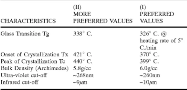
The heavy metal ?uoride glasses produced in accordance With the present invention exhibit the folloWing character
istics:
(II) (1)
MORE PREFERRED CHARACTERISTICS PREFERRED VALUES VALUES
Glass Transition Tg 338° C. 326° C. @ heating rate of 5°
C./min
Onset of Crystallization Tx 421° C. 370° C. Peak of Crystallization Tc 440° C. 399° C.
Bulk Density (Archimedes) 5.8g/cc 6.0g/cc
Ultra-violet cut-off ~268nm ~260nm
Infrared cut-off ~9,um ~10,um
The high density ?uoride glasses in accordance With the
present invention also exhibit transmission characteristics that transmit light in the ultra-violet range.
The heavy metal ?uoride glasses in accordance With the present invention also have a high density.
The high density ?uoride glasses in accordance With the
present invention may also have a high index of refraction.
Although not Wishing to be bound by any particular
theory, it is believed that high density ?uoride glasses having
extended UV and IR transmission ranges are produced in accordance With the present invention and preferably are substantially or essentially devoid of at least one member
selected from the group consisting of thorium, radioactive thorium, and lead. The previously mentioned discoveries of
the present invention are believed notWithstanding that the ?uoride glasses may have a density greater than about 6.0
g/cm3.
In accordance With the present invention, high density
?uoride glasses With extended transmission into the UV and
IR ranges preferably comprise a density greater than about
10 15 20 25 30 35 40 45 50 55 60 65
4
6.0 g/cm3 Which preferably are substantially or essentially
devoid of at least one member selected from the group
consisting of thorium, radioactive thorium, and lead. For purposes of the present invention, the starting
materials, also referred to herein as raW materials, for such
heavy metal ?uoride glasses are compounds of metals that are capable of being converted into ?uorides. Preferably, such starting materials for such heavy metal ?uoride glasses
are materials selected from the group consisting of oxides,
hydroxides, ?uorides, and carbonates, and most preferably
oxides that are capable of being converted into such ?uo rides.
In accordance With the process for the production of such
heavy metal ?uoride glasses, the starting materials identi?ed
above are ?rst converted to ?uorides prior to melting a
resultant ?uoride mixture at predetermined temperatures for
prescribed time periods, quenching the melt, and then
annealing the resultant glass at a temperature beloW the glass transition temperature of the glass.
In accordance With the present invention, it has been noted that emitted ?ux of these glasses When used a Cer enkov detector scales as the inverse square of wavelength,
103.
The heavy metal ?uoride glasses of the present invention
have been discovered to be useful and advantageous over
conventional glasses generally in being denser, exhibit more
UV transmission/transparency, in addition to being more
chemically stable and durable, more easily produced, and
having stronger glass forming abilities and/or capabilities.
The high density of the ?uoride glasses in accordance With the present invention advantageously results in higher
stopping poWer for electromagnetic particles, particularly
When the high density ?uoride glasses are used in detectors,
such as Cerenkov detectors.
The light transmission characteristics of the ?uoride glasses used in accordance With the present invention are
advantageous in increasing ?ux of detectable light, and particularly increasing the ?ux of detectable Cerenkov light. Although not Wishing to be bound by any particular theory, the heavy metal ?uoride glasses of the present
invention are believed to be advantageous, partially in
comparison to the prior art, because the heavy metal ?uoride glasses of the present invention preferably are substantially
or essentially devoid of at least one member selected from
the group consisting of thorium, radioactive thorium, and lead in addition to being essentially devoid of manganese.
The heavy metal ?uoride glasses of the present invention
are also essentially devoid of manganese because it is believed to be a very undesirable component of glass.
The present invention is also directed to apparatus for measurement of time, apparatus for measurement of energy, Cerenkov radiators, and Cerenkov detectors that include
heavy metal ?uoride glasses of the present invention, in
addition to laser ?bers, scintillating glasses, optical
ampli?ers, and imaging equipment, particularly medical
imaging that include heavy metal ?uoride glasses of the present invention.
BRIEF DESCRIPTION OF THE DRAWINGS FIGS. 1 and 1B—1F depict graphs shoWing comparison
data.
FIG. 2 depicts an additional graph shoWing comparison
test data.
FIG. 3 depicts an additional graph shoWing comparison
test data.
FIG. 7 shoWs a Cerenkov apparatus for measuring time
including a heavy metal ?uoride glass in accordance With the present invention.
FIG. 8 shoWs a Cerenkov energy detector including a
heavy metal ?uoride glass in accordance With the present
invention.
DETAILED DESCRIPTION
The folloWing is a detailed description of the present
invention that is intended to be claimed.
In general, the present invention relates to heavy metal ?uoride glasses, methods or processes for preparing heavy metal ?uoride glasses, uses of high density glasses, and
apparatus embodying heavy metal ?uoride glasses Wherein
the heavy metal ?uoride glass comprises a composition
range (in mol percent) of:
High density glasses produced in accordance With the
present invention most preferably comprise a composition
(in mol %) comprising about:
Another more preferred high density glasses produced in
accordance With the present invention comprises a compo
sition (in mol %) comprising about:
26BaF2.18HfF4.12AlF3.1OCdF2.18YbF3.16ZnF2 (II)
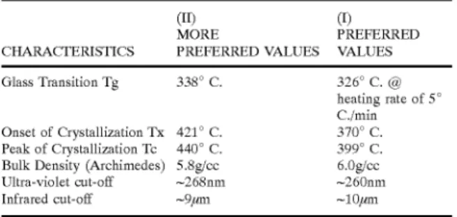
The high density glasses produced in accordance With the
present invention exhibit the folloWing characteristics:
(11) (1)
MORE PREFERRED CHARACTERISTICS PREFERRED VALUES VALUES
Glass Transition Tg 338° C. 326° C. @ heating rate of 5°
C./min
Onset of Crystallization Tx 421° C. 370° C. Peak of Crystallization Tc 440° C. 399° C.
Bulk Density (Archimedes) 5.8g/cc 6.0g/cc
Ultra-violet cut-off ~268nm ~260nm
Infrared cut-off ~9,um ~10,um
Turning ?rst to the methods or processes for producing
heavy metal ?uoride glasses in accordance With the present invention, the method or process for producing heavy metal ?uoride glasses in accordance With the present invention
involves initially converting the starting materials, also referred to as raW materials, into ?uorides. In this regard, the starting materials may be separately or in a mixture con
verted into such ?uorides.
Alternative methods Which have been discovered to be
suitable for converting the starting materials into ?uorides
include:
(i) reaction of raW materials, e.g. metal oxides,
hydroxides, carbonates, or any other metal salts Which
can be converted into ?uorides, With a solid ?uorinat
ing agent, such as NH4HF2; and,
10 15 25 35 45 55 65
from the group consisting of oxides, hydroxides, ?uorides,
carbonates or oxy?uorides of Hf, Ba, In, Ga, and Cd.
Preferably, the starting materials are ?uorides of the said
materials. As used herein, the abbreviations, such as Hf, Ba, In, Ga, and Cd, are the accepted IUPAC abbreviations for the elements, such as Hafnium, Barium, Indium, Gallium, and
Cadmium, respectively.
For purposes of the present invention, a ?uorinating agent
preferably should be used even if all the starting materials are ?uorides. Although not Wishing to be bound by any particular theory, it is believed that this use of a ?uorinating
agent converts the raW materials, such as oxides,
hydroxides, oxy-?uorides, and the like, into ?uorides in a
reaction as folloWs:
(2) (3) (4)
Where M is Hf, Yb, Zn, Pb, or Ba; x=1 or 2; y=1, 2 or 3; and
Z=1, 2, 3 or4.
This use of a ?uorinating agent is also believed to ensure
that oxides and other impurities, if any, are also converted
into ?uorides in reaction as shoWn in Eq. (1) through Eq. (4),
here reWritten as Eq. (5) through Eq. (8):
Where, as above in Eq. (1—4), M is Hf, Yb, Zn, Pb, or Ba; x=1
or 2; y=1, 2 or 3; and Z=1, 2, 3 or 4.
Accordingly, the ?uorides themselves are prevented from
being oxidiZed during the process.
Most preferably for purposes of the present invention, the starting materials are ?uorinated by using NH4HF2 as the
?uorinating agent. HoWever, suitable ?uorinating agents
may be selected from the group consisting of HF, F2, and
SF6.
In accordance With the present invention, the starting
materials, such as the above-identi?ed oxides, are ?rst mixed together With an excess amount of a solid ?uorinating
agent, most preferably NH4HF2. In accordance With the
present invention, it has been discovered that the ratio of
starting materials to ?uorinating agents varies inversely to
the ?uoride content of the starting materials.
More speci?cally, excess NH4HF2 amounts to about 20 Wt
% of the total Weight of the starting ?uorides. Although not Wishing to be bound by any particular theory, the ?uorinat
ing agents are believed to function here to remove
impurities, such as impurities selected from the group con
sisting of oxide impurities and Water impurities from starting
?uorides.
Appropriate amounts of oxides are Weighted out and ground preferably in a mortar and pestle, With excess
NH4HF2 (?uorinating agent), Which may be approximately
US 6,177,372 B1
7
Appropriate amounts of starting ?uorides Were Weighed
out and combined With excess NH4HF2 equal to tWenty
Weight percent of the total Weight of the starting ?uorides.
The purpose of the ?uorinating agent here is to remove any oxide or Water impurities from the starting ?uorides.
Most preferably the synthesiZed ?uorides are added to the
starting ?uorides and excess reagent mixture and ground
thoroughly.
The resultant mixture is then placed into a crucible Which has been previously rinsed out With Water and dried With
high pressure air to ensure that all traces of Water are removed and heated at a predetermined temperature for a
prescribed period of time. Most preferably the oxides are
then placed in a platinum crucible and ?uorinated at about
400° C. for about three hours in an electric tube furnace. The
temperature and time for purposes of this step of the process of the present invention is at least in part dependent upon the
batch amount and the speci?c starting materials used.
The mixture is then placed in the crucible and the excess
?uorinating agent is burned off preferably at about 600° C.
for betWeen about 1—1.5 hours.
Although a crucible is the most preferred form of a vessel in Which the mixture is heated at this stage of the process, other suitable vessels may be used. In any event, for pur poses of the present invention, the crucible or other suitable vessel should be composed of a material selected from the group consisting of vitreous carbon and noble metal, or other
chemicals stable in the presence of high temperature ?uo rides and oxy-?uorides. For purposes of the present invention, noble metals selected from the group consisting of gold, platinum and platinum-rhodium are preferred, With gold and platinum more preferred, and With platinum most
preferred.
The heated mixture is then subjected to additional heating
at higher temperatures for a time suf?cient to melt the heated mixture to result in a melt molten liquid.
For purposes of the present invention, it is preferred to
effect melting in an inert atmosphere. In this regard, the inert atmosphere is provided by an inert gas more preferably selected from the group consisting of argon and nitrogen,
With nitrogen being most preferred.
Most preferably, a lid is then placed on top of the crucible and the furnace temperature is increased up to about 900° C.
and the mixture is heated for about thirty minutes. Although not Wishing to be bound by any particular theory, the
purpose of the lid is believed to create someWhat of a protective atmosphere for the melt by keeping the ?uorinat
ing agent from leaving the crucible to quickly as the last
traces of it burned off.
The melt or melted mixture may then be quenched, for
example by pouring the melt into a preheated mold in Which
it is quenched to form a glass bulk.
Most preferably, the crucible is then removed from the furnace and kept hot using an appropriate burner, such as a Bunsen burner. This step is believed to be necessary to keep the top of the crucible hot in order to avoid crystalliZing the glass as it is poured. The melt is then quickly poured into a preheated brass mold at a temperature most preferably at
about 270° C. to cast the melt as glass discs typically 3 cm in diameter and up to 6 mm in thickness. The mold is then
shut off and alloWed to cool naturally.
For purposes of the present invention, it is important that
the mold be stable at the pouring temperature and have
sufficient capability for quenching. Thus, for purposes of the
present invention, any conventional mold that is stable at the
pouring temperature and has suf?cient quenching ability is
suitable. The materials suitable for making the mold are
10 15 20 25 30 35 40 45 55 65
8
preferably selected from a group consisting of graphite, ceramics, and metals. Preferably, the metal suitable for the
quenching mold comprises at least one material selected
from the group consisting of carbon steel, superalloy, brass, and stainless steel; With brass and/or stainless steel being preferred, and brass being most preferred. Related to this, superalloys selected from the group consisting of Ni-based
superalloys, Fe-based superalloys, and Co-based superalloys are suitable for use in the manufacture of the mold.
Finally, the quenched melt or bulk glass is subjected to
annealing at a predetermined temperature for a prescribed
period of time effective to anneal the glass. The annealing temperature is dependent upon the glass transition tempera ture of the speci?c glass. In this regard, the glass is prefer ably subjected to temperatures beloW the glass transition
temperature of the glass during annealing. Preferably the
glass is subjected to temperatures Within the range of about
250° C. to about 325° C. for a period of time Within the range of about tWo hours to about 10 hours. Most preferably, the
cast glass disks are then annealed at 305° C. in a box furnace
for 16 hours before being polished.
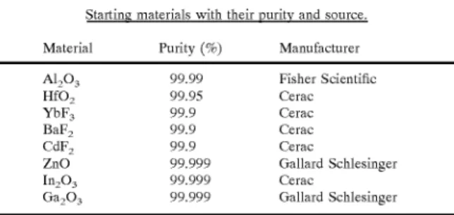
The raW materials used in this project are shoWn beloW in
Table 1. Fluorination of oxides Was accomplished using the
much described ammonium bi?uroide, NH4HF2 method. The appropriate stoichiometric amount of ?uorinating agent
Was determined and then 50 mol % excess as added to
ensure complete ?uorination. First, the ammonium bi?uo ride Was ground With a porcelain mortar and pestle into a very ?ne poWder. The starting ?uorides and oxides Were then mixed in thoroughly With the ammonium bi?uoride
poWder.
TABLE 1
Starting materials With their purity and source.
Material Purity (%) Manufacturer
A1203 99.99 Fisher Scienti?c
HfO2 99.95 Cerac
YbF3 99.9 Cerac
BaF2 99.9 Cerac
CdF2 99.9 Cerac
ZnO 99.999 Gallard Schlesinger
In2O3 99.999 Cerac
Ga2O3 99.999 Gallard Schlesinger
This mixture Was then placed in a 90 Pt/ 10 Ir crucible and
inserted in a tube furnace. The temperature of the furnace
Was raised to 300° C. for 2—6 hours, depending on the initial
siZe of the batch, to alloW the conversion of oxides to
?uorides. The furnace temperature Was then raised to 600°
C. to alloW any excess ?uorinating agent to burn off. After all of the excess ?uorinating reagent Was removed,
the crucible Was taken out of the furnace and alloWed to
cool. The resulting ?uoride poWder Was then ?nely ground
With a mortar and pestle. After grinding, the poWder Was placed back in the crucible and inserted into the furnace
Which Was still operating at a temperature of 600° C. A lid
Was placed on top of the crucible and the temperature of the
furnace Was raised to 900° C. for thirty minutes to melt the
entire sample and alloW for ?ning of the melt to take place.
In the ammonium bi?uoride process, the continuous ?oW
of NH4HF2 protects the melt from atmosphere hydrolysis,
Which occurs for only a feW minutes When the glass is ?rst melted. If a deep crucible is used, hydrolysis does not hinder
glass formation. Adeep crucible design alloWs the glasses to
be made in an ambient atmosphere. The crucible used in this
project had a test tube design With an outer diameter of 21 mm, and a Wall thickness of 0.5 mm. The overall length of
at a rate of 3° C./min up to a temperature about 15—20° C.
beloW the glass transition temperature, in order to anneal the
glass. The annealing time ranged from 16 hours, for samples
2 mm thick, to 36 hours for samples 6 mm thick. The glass
disks Were polished for three minutes per side for each or a
range of polishing papers.
The glass transition temperatures (Tg) Were determined
using a Seiko TG/DTA 3020 scanned at a rate of 10° C./min.
The UV/visible transmission spectra Were measured using a
UV/VIS/NIR Perkin-Elmer Lambda 19 Spectrometer. The
IR transmission spectra Was found using a Bio-Rad Digilab FTS 40 Spectrometer. Bulk densities of the glasses Were
found by the Archimedes method using distilled Water.
TABLE 2
Optimum compositions of the ?uorides glasses in mol %
of the present invention.
Sample HfO2 BaF2 YbF3 InF3 GaF3 ZnF2 CdF2 All:3
I 18 26 1 8 7 5 1 6 1 0 —
II 18 26 — — 16 10 12
Table 2, shoWn above, gives compositions for tWo of the best glass forming samples found in this Work. Sample II Was made by simply substituting 12 mol % AlF3 for the InF3 and GaF3 found in Sample I. As expected, the addition of
AlF3 improved glass forming ability, loWered the density,
raised the Tg, and loWered the IR cut-off of the glass. The
general properties of these glasses are shoWn beloW in Table
3.
TABLE 3
General properties of the ?uoride glasses.
max. thick IR cut-off UV cut-off
Sample p (g/cc) Tg (mm) (,um) (nm)
I 6.0 326 3 10 260 II 5.8 338 >6 9 260
The Group IIA elements, A1 in particular, are considered
to often act as stabliZers in ?uoride glasses. GaF3 and InF3, Which are both heavier and have a much higher density than
AlF3, Were tried ?rst in small amounts to stabiliZe the glass.
Samples using only GaF3 or InF3 Were not glass forming compositions. In addition, combinations of AlF3 and GaF3/
InF3 Were not glass forming. Larger amounts of the Group
IIIA elements Would most likely increase the stability of the
glass, but this Would also dramatically loWer the density of
the glass, as evidenced by the increased thickness and loWer
density of Sample II. Table 4 beloW shoWs the knoWn
densities of the crystalline ?uorides, as Well as ionic radii of
the respective cations.
10 15 20 25 30 35 40 45 50 55 60 65
AlF3 2.88 A1+3 0.057
InF3 4.39 In+3 0.092
CdF2 6.64 Cd+2 0.103
ZnF2 4.95 Zn+2 0.083
YbF3 unknown Yb+3 0.100
HfF4 4.40 Hf+4 0.084
BaF2 4.89 Ba+2 0.143
GaF3 4.47 Ga+3 0.062
Cadmium ?uoride Was chosen because it has an ionic
radius close to that of Zinc, but has a much higher crystalline
density. Also, the addition of CdF2 Would hopefully coun teract the addition of the loWer density Group IIIA elements,
and it appears that it did because partial substitution of
cadmium for Zinc seemed to increase the glass forming character of the system, While maintaining a high density.
HoWever, glasses With less than 4 mol %, or more than 10 mol %, CdF2 Were found to have a greater tendency to
crystalliZe.
Experimental results for this system indicated that higher amounts of BaF2 are good for glass formation. HoWever, it
Was also found that increasing the concentration of the
higher density HfF4 and YbF3 tended to increase the devit
ri?cation rate of the glass.
The glasses of the present invention Were clear and colorless. They also exhibited a loW UV cut-off, as shoWn in FIG. 1. From this data, it does not appear that the group IIIA
element affected the UV cut-off as both glasses have essen
tially the same UV cut-off Wavelength. There is a strong absorption band from ~850—1050 nm due to the rare-earth ion, Yb+3. This band does not affect the UV or visible regions of the glass. Tests Were done to see if this absorption
band could be eliminated by substituting another trivalent
ion into the glass, such as yttrium and lanthanum, but these compositions Were not glass forming. Attempts Were also made to shift the band by using tWo other rare-earth elements, Cerium and Gadolinium. Other elements, such as Europium, Terbium, Erbium, and Lutetium Were not tested. Only heavy metal ?uorides Were considered in the interest of
keeping the density of the glass as high as possible.
The IR cut-off of these glasses is shoWn in FIG. 1E. As
expected, the cut-off of glass I is higher than that of glass II
because of the heavier group IIIA elements, In and Ga. The amount of Water absorption seen in the samples could be
reduced dramatically by preparing the samples in a protec
tive atmosphere such as N2.
Preferably, heavy metal ?uoride glasses produced in
accordance With the present invention comprise a composi tion range (in mol percent) selected from the group consist
ing of:
A more preferred heavy metal ?uoride glass produced in
accordance With the present invention comprises a compo
sition (in mol %) comprising about:
A more preferred heavy metal ?uoride glass produced in
accordance With the present invention have a maximum
US 6,177,372 B1
11
Another more preferred heavy metal ?uoride glass pro
duced in accordance With the present invention comprises a
composition (in mol %) comprising about:
26BaF2.18HfF4.12AlF3.10CdF2.18YbF3.16ZnF2 (II) A more preferred heavy metal ?uoride glass produced in
accordance With the present invention have a maximum thickness of most preferably greater than about 6 mm.
The heavy metal ?uoride glasses produced in accordance With the present invention exhibit the folloWing character
istics:
(II) (I)
MORE PREFERRED CHARACTERISTICS PREFERRED VALUES VALUES
Glass Transition Tg 338° C. 326° C. @
heating of 5° C./min
Onset of Crystallization Tx 421° C. 370° C. Peak of Crystallization Tc 440° C. 399° C.
Bulk Density (Archimedes) 5.8g/cc 6.0g/cc
Ultra-violet cut-off ~268nm ~260nm
Infrared cut-off ~9,um ~10,um
The densities of the glass samples Were determined by the
Archimedes method. Distilled Water Was used as the
immersing medium. The glass transition temperatures Were tested by using a Differential Scanning Calorimeter. The
UV/visible transmission spectra Were measured by using a
UV/VIS/NIR Spectrometer.
The folloWing examples are provided to illustrate the present invention.
EXAMPLE I
The synthesiZed ?uorides are added to the starting ?uo
rides and excess reagent mixture and ground thoroughly.
The crucible is then rinsed out With Water and dried With high pressure air to ensure that all traces of Water are
removed. The mixture is then placed in the crucible and the excess ?uorinating agent is burned off at about 600° C. for betWeen about 1—1.5 hours. Alid is then placed on top of the crucible and the furnace is turned up to about 900° C. for about thirty minutes. The crucible is then removed from the
furnace and kept hot using an appropriate burner. The melt
is then quickly poured into a preheated brass mold that Was at about 270° C. The mold is then shut off and alloWed to
cool naturally.
EXAMPLE II
The raW materials used Were the same as in Example I. The process Was the same as Example I except that the
annealing temperature in Example II Was different.
The emission of Cerenkov radiation in the UV and visible optical ranges is a Well-knoWn property of relativistic par ticles in transparent media.
The mechanisms of energy loss, multiple scattering and
Cerenkov emission of light in materials are knoWn, and these processes Were simulated exactly for these examples. The detection of the Cerenkov photons is simulated With a Burle photomultiplier tube (PMT) C31000M. TWo other Burle PMT’s Were simulated, the C83060 and the C83063E, Which Were both inferior in performance to C31000M for
Cerenkov light in all glass. The transmission of light through
10 15 20 25 30 35 40 45 50 55 60 65
12
samples Example I and Example II Was taken from mea surements; and transmission through the materials Were
taken from the measurements described by E. Ramberg,
“PbF2 for High-Rate, High Energy Calorimetry,” Calorim
etry in High Energy Physics, eds. D. F. Anderson, Fermilab,
Oct. 29—Nov. 1, 1990, the disclosures of Which are incor
porated in their entirety by reference thereto herein.
PbF2 has been investigated as a Cerenkov detector by the
high energy physics community, and SP5 is a neWly manu factured and commercially available ‘lead-glass’ material.
For purposes of these examples, tWo sources have been simulated: a 0.478 MeV electron (from a backscattered
0.6617 MeV 137Cs )t-ray) and a minimum-ioniZing high energy p lepton.
The pulse height distributions for incident 0.478 MeV
electrons are displayed in FIGS. 1(a—a) for the four com
parison materials, (a) Example I, (b) Example II, (c) SP5,
and (d) PbF2. The samples simulated Were each 1-mm thick,
Where the average range of these 0.478 MeV electrons is about 0.04 cm. The number of events With Zero pulse height is a direct measure of the ine?iciency of the e'%sample— aPMT detection chain.
The mean pulse height and the detection e?iciency for
each material are listed in the folloWing table. The Example
1 glass is superior to all others in performance.
Energy/Particle Medium Pulse Height E?iciency
0.478 MeV e’ Eg. I 1.80 pe 82% 0.478 MeV e’ Eg. II 1.33 pe 69%
0.478 MeV e’ SF5 1.12 pe 65%
0.478 MeV e’ PbF2 1.35 pe 71%
The pulse height distributions for incident 1 GeV p’s are
displayed beloW (a—d) for the same materials, (a) Example
I, (b) Example II, (c) SP5, and (d) PbF2. This energetic p
passes through the 1-mm samples. The mean pulse height
distributions are listed in the folloWing table. The samples
all had comparable e?iciency.
Energy/Particle Medium Pulse Height
1 GeV ,u Eg. I 11.4 pe
1 GeV ,u Eg. II 8.9 pe
1 GeV ,u SF5 5.0 pe
1 GeV/1 PbF2 10.1 pe
Although not Wishing to be bound by any particular
theory, the superior performance of the Example I glass is
attributed to its superior transmission in the ultra-violet
(UV), and the subsequent high e?iciency of the Burle
photocathode in the UV range.
The present invention has been unexpectedly discovered
to result in high density glasses having suf?cient stopping
poWer for nuclear particles, and transition doWn into the
ultraviolet range so as to result in a higher ?ux of light, and,
therefore, higher efficiency and higher precision.
Although not Wishing to be bound by any particular
theory, the foregoing characteristics of the high density glass
produced in accordance With the present invention are
Where the indeX of refraction may be Wavelength-dependent and the ?uX is in units of photons per unit Wavelength per
unit track length in the glass.
It has also been discovered that the high density glass produced in accordance With the present invention is par
ticularly useful in science and technology as applied to any
crystalline material sensitive to the passage of ioniZing
radiation, including devices to measure time, and devices to
measure energy.
HarshaW Chemical, Bicron, ReXon, and similar
companies, routinely produce crystalline scintillators and
Cerenkov media. The glassy materials of the present inven
tion are intended to function in an advantageous manner in
such devices.
As to the measurement of time, Cerenkov light is emitted
instantaneously; and, therefore, provides an immediate sig
nal for the presence of a charged particle. For eXample, in
medical applications of positron emission tomography (PET), a positron from a radioactive source annihilates an
atomic electron in a sample, resulting in 2 y-rays having an energy of about 0.511 MeV, Which are geometrically back
to-back. Thus, it is necessary to localiZe impact points of the y-rays for imaging. Background to the image consists of
scattered y-rays, and y-rays from other annihilations. These background hits are usually out of time With the correct hit,
and can be eliminated by stringent timing conditions on the
y-rays pairs accepted as annihilation events. With Cerenkov
radiation, a timing WindoW as small as 5 ns is easily achievable and reduces background from one MHZ sources
by a factor of 200.
As to devices to measure energy, also referred to as
calorimeters in high energy and nuclear physics, photons in the visible, the integral ?uX is about 300 photons per centimeter of charged particle track linked in the glass. Therefore, the optical ?uX is proportional to track length,
Which is proportional to the number of tracks, Which is proportional to the incident particle energy. This provides an
effective means of high energy electromagnetic particle
energy measurement above a feW GeV.
A Cerenkov detector comprising glasses I and/or II With
characteristics in accordance With the present invention may
be optically coupled to a photomultiplier 43 With high quantum e?iciency in the UV (ultraviolet) doWn to about
215 nm. The combination of a Cerenkov radiator With
optical transmission and photocathode efficiency doWn to
about 215 nm constitutes a detector of ioniZation radiation.
The surfaces of the glass are coated With a thin layer of Te?on of aluminiZed Mylar, of any other re?ective material
less than about 1 mg/cm2. The high optical indeX of refrac
tion results in total internal re?ection of most of the Ceren kov light. The re?ective coating re?ects most of the remain
ing light, resulting in a highly efficient light gathering
medium.
Although not Wishing to be bound to any particular theory, the method of detecting Cerenkov light radiation using glasses of the present invention is believed to be
uneXpectantly advantageous due at least in part to the fact that the glasses of the present invention are transparent to the
bulk of the produced Cerenkov light Which travels through the glass to the photocathode of the PMT.
1O 15 25 35 45 55 65
54 is a point of primary Compton scatter of photoelectric
conversion. 55 is a point of secondary scatter of conversion. 56 is a point of tertiary scatter or conversion. 57 is Cerenkov
light emitted form charged particle (in this case, an electron
or positron) Which has velocity v>c/n Where n is the indeX
of refraction and c is the velocity of light. 58 is optical Cerenkov light re?ected and captures by a photocathode of
the PMT.
The efficiency of the glass of the present invention is advantageous at least in part due to: the high optical
indeX, n, (ii) the higher density of the material, (iii) the higher average atomic number, Z, of the material, and (iv)
the net collected Cerenkov light is larger due to the superior transmission of light in the ultraviolet.
A method of radiating Cerenkov light using glasses of the
present invention is believed to be uneXpectantly advanta geous due at least in part to the fact that the glasses of the
present invention have characteristics, including: higher
density, (ii) higher indeX of refraction, (iii) higher transmis
sion of the generated Cerenkov light in the ultraviolet (UV) optical range, and (iv) higher average atomic number of the materials of the glass.
A Cerenkov apparatus for measuring time comprises
glasses 61 With characteristics in accordance With the
present invention, optically coupled to a photomultiplier 63
With high quantum efficiency in the UV (ultraviolet). Since
the emission of Cerenkov light is substantially instantaneous
along the particle trajectory, and since the particles are
relativistic, the emitted light forms a ?at disc of light travelling through the Cerenkov radiator. Furthermore, the
high density of the radiator necessitates a shorter and more
compact radiator.
The time dispersion on Cerenkov photon arrival time at
the photocathode of the PMT is about L/c(n2—1), Where L is the length of the glass 61. For L=5 cm, this time dispersion
is 0.25 ns, Well-matched to the time resolution of a good, fast
high-quality PMT.
The method for measuring time in accordance With the
present invention using glasses comprising the properties of:
(i) higher density, (ii) high optical indeX, and (iii) high
transmission in the UV is believed to be uneXpectantly advantageous due at least in part to the fact that the high
density results in a more spatially compact material, the high
indeX results in more total internal re?ection of the Ceren
kov light, and the high transmission in the UV results in more light into the PMT. The luminous light from the glasses of the present invention is recorded by the leading edge of
the PMT output pulse, Which is more abrupt in time due to
these properties.
A Cerenkov energy detector comprising glasses 71a, b, c,
a' With characteristics in accordance With the present
invention, optically coupled to a photomultiplier 73a, b, c, a'
With high quantum e?iciency in the UV (ultraviolet) doWn
to about 215 nm. The total emitted Cerenkov light is
proportional to the total pathlength of relativistic particles;
and, therefore, a measurement of the intensity of Cerenkov light is a measure of the incident particle energy. The higher
density of the Cerenkov radiator improves the quality of the
energy measurement over previous detectors since the total
particle energy is absorbed in a shorter spatial distance. All of the incident energy of the particle is converted into
US 6,177,372 B1
15
therefore, the total incident energy is proportional to the total
Cerenkov light emitted. The peak pulse of the PMT mea
sures the amount of light; and, therefore the energy. The high density of the glasses of the present invention ensure that all of the incident particle’s energy is converted into neW
particles.
The method of energy measurement of the present inven
tion involves copious production of light due to high
density, (ii) high index of refraction, and (iii) high transmis sion in the UV. All three factors alloW a measurement of the energy of a particle by measuring the peak pulse height of
the PMT pulse.
Heavy metal ?uoride glasses in accordance With the
present invention are particularly useful in laser ?bers.
Heavy metal ?uoride glasses in accordance With the present invention are particularly useful in scintillating
glass.
Heavy metal ?uoride glasses in accordance With the present invention are particularly useful in optical ampli?
ers.
In addition, the heavy metal ?uoride glasses of the present
invention are also useful and advantageous in medical
imaging systems, x-ray detection systems, laser systems,
and optical systems.
The heavy metal ?uoride glasses of the present invention
are someWhat sensitive to moisture When ?rst cast. A thin
?lm develops on the surface of the glass, but this is easily removed during polishing. Although not Wishing to be
bound by any particular theory, the purity and quality of
these heavy metal ?uoride glasses of the present invention
may be improved by making these heavy metal ?uoride
glasses in a glove box under a protective atmosphere free of
oxygen and Water.
Some of the heavy metal ?uoride glasses are a bit irregu lar in shape. The small, White pieces found in some of the specimens are believed to be traces of unmelted poWder.
Notwithstanding irregularity in shape and unmelted poW
der in some of the glasses, this Was still a good glass forming
composition as evidenced by the absence of crystalliZation in the samples.
The numbers Which appear in brackets refer to the refer ences listed in the section of this application entitled Back
ground Art; the disclosure of such references in their entire
ties being incorporated by reference thereto herein.
Having thereby described the subject matter of the present invention, it should be apparent that many substitutions,
15
25
35
45
16
modi?cation and variations of the invention are possible in
light of the above teachings. It is, therefore, to be understood
that the invention is taught and described here and is only to
be limited to the extent of breadth and scope of amended
claims.
What is claimed:
1. A high-density glass, comprising heavy metal ?uoride glass comprising a composition range (in mol percent):
(16—30)BaF2; (8—26)HfF4; (6—24) of (0—24)InF3, (0—24)
GaF3 and (0—19)AlF3; (1—16)CdF2; (6—24)YbF3; and (4—26)
ZnF2.
2. The high density glass of claim 1, comprising a
composition comprising about 26 BaF2; 18 HfF4; 7 InF3;
5GaF3; 10CdF2; 18YbF3; and 16ZnF2.
3. The high density glass of claim 1, comprising a
composition comprising about 26 BaF2; 18 HfF4; 12AlF3;
10CdF2; 18YbF3; and 16ZnF2.
4. Aprocess for producing the high density glass accord
ing to claim 1, said process comprising:
(a) converting materials into ?uorides in amounts suf?
cient to form said glass;
(b) melting said ?uorides at a melt temperature for a time suf?cient to produce a melt;
(c) quenching said melt to produce a quenched melt; and (d) subjecting the quenched melt to an annealing tem
perature for a time sufficient to anneal the resultant
glass.
5. The process of claim 4, Wherein said materials are
selected from the group consisting of metal oxides, hydroxides, and carbonates capable of being converted to
?uorides.
6. The process of claim 5, Wherein said melt temperature is about 800° C.
7. The process of claim 6, Wherein said melt time is Within the range of about 10 minutes to about 60 minutes.
8. The process of claim 4, Wherein said annealing tem perature is a temperature less than the glass transition
temperature of the glass.
9. The process of claim 4, Wherein said resultant glass comprises a composition comprising about 26 BaF2; 18
HfF4; 7 InF3; 5GaF3; 10CdF2; 18YbF3; and 16ZnF2.
10. The process of claim 4, Wherein said resultant glass comprises a composition comprising about 26 BaF2; 18
HfF4; 12AlF3; 10CdF2; 18YbF3; and 16ZnF2.