International Journal of Innovative Technology and Exploring Engineering (IJITEE) ISSN: 2278-3075, Volume-8 Issue-12, October 2019
Abstract: In this analysis, the liquid flow and heat transfer in micro channel heat sink (MCHS) to find the pressure drop are experimentally investigated by three degree slope in manifolds in addition to the arrangement of micro channels. This experimental analysis is executed with respect to the Nusselt Number and Heat transfer characteristics for three manifolds with different arrangement. We are working on this experiment at three different arrangement manifolds: Arrangement (A) is the three-degree slope in manifolds downward and upward, Arrangement (B) is the three-degree slope in manifolds upward and downward and Arrangement (C) is the three-degree slope in upward direction of the manifolds are selected. In this investigation we are using the Reynolds number ranging from 705-1411 for micro channel heat sink. The Arrangement (A) is the greater heat transfer coefficient within the increase Nusselt number and velocity and low pressure drop in comparison to Arrangement (B) and (C) type manifolds.
Keywords : Pressure drop, Heat transfer, Micro channel Heat sink, Reynolds Number, Manifolds.
I. INTRODUCTION
Heat Transfer effects the liquid flow in micro channels
manifolds heat sink. Convection is a process in which heat transfer in gases or liquid when it flows above the surfaces. The gases or liquid flow above the surface, and it convey heat to the surface depending upon the different temperatures. MCHS is of individual interest to very high rate of heat transfer they authorized in the concurrence with very much reduced the heat exchanger length and coolant mass. A consequential number of researches have been exclusive to micro channel heat sink conduct in recent years. In 1981, D.B. Tuckerman and pease [1] identify the decreasing fluid cooling channels measurement to the microns scale will prompt the heat transfer rate are increases. They are additionally tentatively that an improvement in heat exchanger ability in Silicon based micro-channels anemically clung to pyre spread chips. Qu et al. [2,3] led tests toward examine stream qualities of water through silicon trapezoidal micro-channels with the pressure-driven breadth going from 51 μm to 169 μm. Their outcomes show that the weight inclination and stream erosion in the micro-channels are greater than those given through the ordinary stream in laminar hypothesis because of the impact of surface harshness of the micro-channels. Along these lines, they proposed an unpleasantness thickness model to translate the test data. Peterson and Peng [4, 5] executed trialRevised Manuscript Received on October 05, 2019. * Correspondence Author
Devender kumar*, Department of Mechanical Engineering . Chandigarh University, Punjab, India [email protected]
Harpreet singh, Department of Mechanical Engineering . Chandigarh University, Punjab, India [email protected]
examinations happening weight droplet or convective heat transversal for liquid stream on quadrilateral straight micro-channels. It remained discovered the cross-sectional viewpoint proportion impacted the stream erosion then convective heat transfer for both in laminar and stormy flows in liquid. Philips [6] projected a strategy for deciding general thermal resistance by a component in relevant factors. He played out an affectability investigation to assess different parametric impacts on his experiment and stretched out the investigation to incorporate bigger channel widths of rectangle -shaped micro-channels with temperate viewpoint proportion then for completely creating streams in laminar or turbulent flows. Test areas were manufactured utilizing phosphate as the wafer material was utilized the work in liquid. Wu, Cheng [7] analyzed tentatively the contact factors in even silicon trapezoidal straight micro-channels through various viewpoint proportions. They was presumed the fRe of liquid flows in micro channels, requiring the equivalent pressure-driven distance across yet with various transaction structures, can be particularly extraordinary due to the transactional figure of micro channel chips. Wang [8] planned the non-symmetrical helical organize framework the research and impacts on bend or torsion of low range Reynolds number stream in spiral pipe. Friedrich and Huttl [9, 10] Analysis mathematically impacts of ebb flow and torsion on the fierce stream in a helically wound channels. Results must demonstrate was the stream amounts stood influenced through the pipe ebb and flow, though the torsion impact was little and it can't be ignored. Sehgal SS, Murugesen K, Mohapatra SK [11] analyzed experimentally the fluid flow arrangement and effects on the presentation of microchannel heat exchanger.This investigation worked at the widthfor each microchannel is 331µm and depth 2.5 mm. And the effects of S, P, plus U – the flow type of arrangements are studied by 3 different 125W, 225W and 375W heat inputs, and the Reynolds no. range 224-1121. In this research, it observed that greater heat transfer amountin U – type flow arrangement is better than others, but the p-type flow arrangement is lower pressure drop has effective performance. Sehgal SS, Mohapatra SK, Murugsen k [12] investigated is experimentally in the effects of microchannel heat sink and the plenums aspect ratio with different fluid flow engagements S, U and P- type microchannel heat sink and various Reynolds number at the different warmth inputs in sink. In this work microchannel pieces the aspect ratio in two- microchannel, 4.72 and 7.57 the three aspect ratio of 3 plenums, 2.5, 3.0, and 3.75 are tested. In this investigation, nusselt number is increased
126 to 165%, has been observed, the increased length in manifolds (decrease in the
Effect of Taper Manifolds with Different Slopes
in Microchannel Heat Sink
manifolds aspect ratios defineas per length to width of manifolds) the result increases the nusselt number 18 to 26%. The maximum pressure drop is S – type arrangement the increase the aspect ratio in manifolds, and there is decrease pressure drop in p typefluid stream arrangements. The p-type arrangements the pressure drop is minimum. Wang j [13] investigated the pressure drop and fluid flow rotation in parallel channel Z – type arrangement. This investigation show, the model based on momentum and mass equations has been prepared.
II. METHODOLOGY
The Design of microchannel heat exchanger shown in figures (1-5). Assembly of a microchannel heat exchanger with different tapered manifolds arrangement shows in figures. The selected material for micro-channel is copper (Cu) and the acrylic sheet cover is used. The parameters on the micro-channels heat exchanger and acrylic sheet cover is given by the Table no.1. The different specifications are taken into contemplation for the study is shown in Table no.2. Experimental study has been carrying out water as a fluid. The given result all readings have been holding for the calculations. These all readings are used to determining for finding the results.
Fig.1 MCHS Original Test pieces copper material.
.
Fig.2 Slope of Arrangement (A)
Fig.3 Slope of Arrangement (B)
Fig.4 Slope of Arrangement (C)
International Journal of Innovative Technology and Exploring Engineering (IJITEE) ISSN: 2278-3075, Volume-8 Issue-12, October 2019
Table 1. Specification Of The Micro Channels.
Channels Width 500 µm
Spacing B/w Channels 500 µm
Thickness base plate 8000 µm
Channels Length 24500 µm
Channels Depth 3000 µm
Cover plate thickness 8000 µm
Slope of manifolds 3 degree
Table 2. Thermal Hydraulic Parameters.
Flow(LPH) 4, 6, 8,LPH
Wattage 50W, 75W, 100W
Base, fluid Water
Experiments performed 27
Flow, type perpendicular
Reynolds Number 705 - 1411
Work pieces 3
The steps of calculation procedure:- 1. Reynolds Number
Re =
2. Temperature Difference ∆T = Tw - Tavg̮
Tw = Temperature of wall
The heat input is constant supplied on the bottom of micro-channels heat sink.Thermocouplesarelocated in heat sink in bottom surfaces for observing the wall temperature. 3. Average Temperature
Tavg =
T1 Inlet Temperature
T2 Outlet Temperature
4. Heat transfer Coefficient h =
5. Flow Discharge q = mcp∆t
6. Nusselt Number
Nu =
III. RESULTANDDISCUSSIONS
3.1 Variation of heat Transfer Coefficient with in Reynolds Number.
According to this experiment we compare the three different flow rate (4, 6, 8 LPH) in a three different wattages (50,75, and 100W). At last we found the conclusion, the heat transfer coefficient of the Downward - upward manifold is the higher among two different manifolds followed by upward – downward and both upward manifolds Figures 4 – 7.
600 900 1200 1500
[image:3.595.60.279.73.218.2]0 500 1000 1500 H ea t t ra nsf er co ef fici en t (W /m^ 2K) Reynolds number Downward-Upward Upward-Downward Both Upward
Fig.4 Reynolds Number vs. Heat transfer coefficientat 50W
600 900 1200 1500
300 600 900 1200 H e a t t ra n sf e r co e ffi ci e n t (W /m^ 2 K) Reynolds number Downward-Upward Upward-Downward Both Upward
Fig.5 Reynolds Number vs. Heat Transfer Coefficient at 75W
600 900 1200 1500
200 400 600 H e a t tra n sf e r co e ff ici e n t (W /m^ 2 K) Reynolds number Downward-Upward Upward-Downward Both Upward
Fig.6 Reynolds Number vs. Heat Transfer Coefficient at 100W
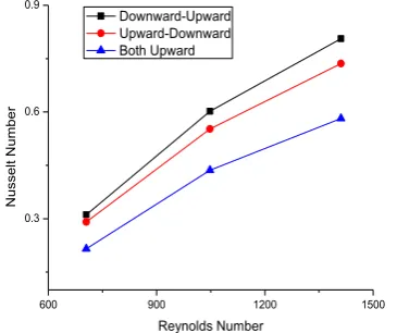
3.2 Variation of Nusselt Number with in Reynolds Number
According to this experiment we found the variation of Nusselt Number with in Reynolds number the experiments comparisons have been prepared at the three different (50, 75, 100 W) wattage‟s and different flow rates (4, 6, 8 LPH). At last we found the conclusion
[image:3.595.326.508.259.402.2] [image:3.595.331.522.472.634.2]manifolds is greater between the two followed through upward-Downward or both upward manifolds Figures (7 –10).
600 900 1200 1500
0.7 1.4 2.1
N
u
ssel
t
N
u
mb
e
r
Reynolds Number Downward-Upward Upward-Downward Both Upward
[image:4.595.330.527.92.223.2]Fig. 7 Nusselt Number vs. Reynolds Number at 50W.
600 900 1200 1500
0.5 1.0 1.5
N
u
ssel
t
N
u
mb
e
r
Reynolds Number Downward-Upward Upward-Downward Both Upward
[image:4.595.80.265.108.258.2]
Fig.8 Nusselt Number vs. Reynolds Number at 75W.
600 900 1200 1500
0.3 0.6 0.9
N
u
ssel
t
N
u
mb
e
r
Reynolds Number Downward-Upward Upward-Downward Both Upward
Fig.9 Nusselt Number vs. Reynolds Number at 100W. 3.3 Variation of the Reynolds Number with in pressure drop :
Through the experiments the low pressure drop increase with Reynolds Number in downward -upward manifolds
arrangements. The Downward-Upward manifolds
arrangement is better than other arrangements of manifolds Figure 10.
600 900 1200 1500
300 600 900
Pre
ssur
e
dro
p
[image:4.595.74.264.320.487.2]Reynolds number Downward-Upward Upward-Downward Both Upward
Fig. 10 Reynolds Number vs. Pressure Drop.
IV. CONCLUSION
In this experimental study calculate the heat transfer characteristics or pressure drop within Reynolds number on Microchannel heat sinks (MCHS) using water as base fluid. This experiment is done by 3 different flow rates (4, 6, and 8 LPH). Pressure drop is dependent upon Reynolds Number. The pressure drop also played a major role in heat transfer characteristics on the micro channels. The heat transfer coefficient is increased with Reynolds Number in downward – upward manifolds. The Nusselt Number also parallels increased as Reynolds Number. We observe the heat transfer coefficient in Downward-Upward manifolds are greater than upward– downward and both upward manifolds. And both the manifolds are using different heat inputs (50, 75, and 100W). Three degree slope in manifolds which played an important role in reduce the pressure drop to increasing the flow area in flow direction. The slope in micro channels manifold also advantages to improving the overall substantiality.
REFERENCES
1. D. B. Tuckerman, R. F. Pease, [1981] High performance heat exchangerplatesfor VLSI. IEEE Electron devices. Lett EDL 127 -129. 2. W. Qu. G. M. Mala, L. Dongquing. Int. J., [1999] Pressure driven water flows in the trapezoidal silicon. Micro channels heat sink. 354 - 364. 3. W. Qu. G. M. Mala, L. Dongquing. Int. J., [2000] Fluid flow and heat
transfer in trapezoidal silicon micro-channels. 3925 – 3936. 4. X. F. Peng, G. P. Peterson, [1995]the consequence of thermos fluid
geometrical dimensions on convention of liquids in rectangular micro-channels 755 – 758.
5. X. F. Peng, G. P. Peterson, [1996]„Convective heat transfer and friction flow for fluid flow in micro-channels heat sink. 2597 – 2608. 6. R. J. Phillips, [1987] forced convection in liquid cooling in
micro-channels heat sink.
7. H. Y. Wu. P. Cheng, [2002] Experimental analysis of convective heat transfer in silicon micro-channels heat sink with different surfaces conditions Int. J. 2547 – 2856.
8. Q. W. Wang, C. L. Z, M.Zeng, Y.N. Wa, [2008] Numerically investigated of rare field diatomic gas flow or heat transfer in micro-channels using DSMC with static Boundary conditions in heat fluxes. 5498 – 509.
9. T. J. Huttl, R. Friedrich, [2000] Curvature of influence and torsion on turbulent flow in helical and curved coiled pipes.2549 – 65. 10. T. J. Huttl, R. Friedrich, [2001] numericallysimulation of turbulent
flow in helically and curved coiled pipes. 2549 – 67.
[image:4.595.74.257.551.704.2]International Journal of Innovative Technology and Exploring Engineering (IJITEE) ISSN: 2278-3075, Volume-8 Issue-12, October 2019
Author-1 Photo
Author-2 Photo
12. S.S. Sehgal, Murugsen K, Mohapatra SK., [2011 experimentally investigation in Micro channels heat sink and effect of flow adjustment‟s on the Performance of micro channels.215 – 33. 13. Wang J. [2010] Flow distribution and pressure drop in parallel
channels configurations of fuel cells in Z – type arrangements. 175 – 93.
14. Kalani, A., and Kandlikar, S. G., [2014], “Effect of taper manifolds on pressure recovery during flow boiling inopen micro channels with using homogeneous flow model,” Int. J. Heat Mass Transf., 83,pp. 110–117.
AUTHORSPROFILE
Devender kumar, Researcher at Chandigarh University, Deptt. of Mechanical Engineering,, Thermal Engineering. B. Tech from lala lajpat rai institute of engineering and technology moga, Research area Microchannel manifolds and compact heat exchangers.