International Journal of Innovative Technology and Exploring Engineering (IJITEE) ISSN: 2278-3075, Volume-8, Issue-9S, July 2019
Abstract: A Wireless Power Transfer system consists of a transmitter coil which is inductively coupled with secondary coil and is popular for wireless charging of future office communication system. Wireless power transfer is used in different applications ranging from mobile chargers to charging stations. In this paper simulation of Wireless Power Transfer for future office communication systems has been conducted over Maxwell 3d of Ansys electromagnetic suite. The input frequency of primary coil is varied from 1kHz -120kHz with respect to the change in resonant capacitance and observed that input frequency between 20kHz-30 kHz, the output power in secondary coil appears to be maximum at variable distances between transmitter coil and receiver coil. There is an improvement of 72% seen in the output power of secondary coil for 25kHz input frequency of primary coil as compared with 40kHz input frequency. This model can be helpful to design future Office Communication systems for charging the mobile phones, Laptops and to turn on the printer wirelessly.
Index Terms: Communication System, Laptop Charger, Mobile Charger, Receiver Coil, Transmitter Coil, WPT(Wireless Power Transfer)
I. INTRODUCTION
Wireless power transfer (WPT) has been demonstrated using various WPT systems, such as Acoustic [1], [2]; Light [3]; Microwave [4]; Laser [5]; Capacitive [6]; and Inductive [7]. The basic layout of all WPT systems is similar. They all consist of a transmitter connected to a primary electronic circuit and a receiver connected to a secondary electronics circuit. The ‘medium of power transfer’ between receiver and transmitter makes them different from each other. It has been established that an inductive WPT system has the potential to be applied for medium and high power applications, and particularly for the charging of batteries. This method of power transfer has also been referred, contactless power transfer (CPT), contactless energy transfer (CET), inductively coupled power transfer (ICPT), resonant inductive power transfer (RIPT) and inductive power transfer (IPT). Resonant inductive power transfer (IPT) is not a new concept, and many attempts have been made in the past to transmit power wirelessly, most notably by Nikola Tesla (1856 –1943) in the late 1800s and early 1900s. He was inspired by the work of Heinrich Hertz (1857–1984) who first confirmed the existence of electromagnetic radiation in his experiments in 1888. Tesla reported several experimental setups of his WPT
Revised Manuscript Received on June 15, 2019.
Lala Bhaskar, Electronics and Communication Engineering, Amity University, Uttar Pradesh, Noida, India.
Pradeep Kumar, Electronics and Communication Engineering, Amity University, Uttar Pradesh, Noida, India
Kishore Naik Mude, Systec R&D, Porto, Portugal .
study using a high-frequency oscillator for
[image:1.595.339.537.241.369.2]medical/therapeutic applications [8]. Figure 1 shows a simplified schematic of one of his experimental setup to power a light bulb wirelessly using RIPT system.
Figure 1 RIPT setup suggested by Tesla[8], [9]
In Figure 1 the circuit contains two loosely coupled and tuned resonant circuits as primary (P) and secondary (S). An external capacitor C is used to tune the primary while self-capacitance of the solenoid coil is applied to tune the secondary coil. The operating frequency used by Tesla was in the range between 20-100 kHz. Periodic spark gap discharges were used to control the power in the resonant circuit, as the modern resonant converter do today by using power electronic switches. Also, these discharges convert the mains frequency to high frequency of the resonant circuit. It is worth noting that Tesla’s experiments were first to demonstrate power transfer using a resonant inductive link and forms the basis of the majority of today’s modern wireless power transfer system.
Figure 2 The Block Diagram of WPT System
Simulation Analysis of Wireless Power Transfer
for Future Office Communication Systems
[image:1.595.304.559.578.723.2]II. COILANALYSIS
Accurate physical modeling of the Archimedean spiral (inductor) is important since, once built, it is difficult to modify the spiral. In [10], [11], Wheeler presented several formulas for planar spiral inductors, which were intended for the discrete inductors. In [12], a modified expression of Wheeler formulas was given for spiral, square, hexagonal and octagonal planar coils but it relies on lookup tables. In this paper, an amended form of the original Wheeler formula for an Archimedean spiral coil has been used to calculate the geometric parameters of the spiral coil from the estimated value of self-inductance. Figure 3 shows the representation of an Archimedean spiral.
(a)
[image:2.595.305.549.429.648.2](b)
Figure 3 Physical representation of Archimedean spiral (a) 3-D view [13] (b) Cross-sectional view
The expression for inductance is given as :
L=N2A2/(30A-11D i)
Where A=[Di+N(W+S)]/2
From Figure 3 it is obvious that Dout is the outer diameter, Din is inner diameter, S is the spacing between turns and W is the diameter of the wire used for making the coil.
Skin Effects:
For optimal transmission we use high frequencies of input EMF. As a result of frequency increase the depth to which the conduction occurs is reduced by a significant amount given by the formula
The solution to our problem is to use stranded wire which reduces skin effect to a considerable amount.
Proximity Effects:
The distance between two strands of wire (p) should be greater than or equal to 2.5 times of wire thickness (w) P >= 2.5W
III. SIMULATIONANALYSIS
Simulations have been conducted over Maxwell 3d of Ansys electromagnetic suite. For simulation, a transmission coil and a receiver coil have been made over Maxwell 3d. Both the transmission and receiver coils have a wire of cross sectional diameter 1.5 millimeters, the transmitter coil has 30 turns and the receiver coil has 30 turns. Both the coils have two terminals each extruding from the coils to the face of a region box which is of vacuum, hence the region where the simulation of the coils is conducted is vacuum. Magnetic field simulation has been made over the coils with respect to the vacuum box. The two coils are designed over Ansys electromagnetic suite, where they are identical and both are of copper. The color difference is only to identify the difference between the transmitter and the receiver coils. The following parameters have been considered for designing the both the primary and secondary coils as Di=50mm, N=30, W=1.5mm, S=0.2mm and D0=152mm
Figure 4 Transmission and receiver coils in Alignment (with terminals)
International Journal of Innovative Technology and Exploring Engineering (IJITEE) ISSN: 2278-3075, Volume-8, Issue-9S, July 2019
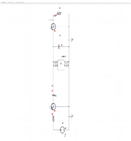
Figure 5 Schematic of Circuit made on Twin Builder
[image:3.595.46.262.47.279.2]Initially the distance between the primary to secondary coil is taken as 5mm and the input frequency is 40kHz. Theoretically the inductance is calculated as 93.64 µH and the simulated mutual inductance is 177.47µH(adjusted to the material and the effect of addition of terminals). The coupling coefficient is 0.9164 which is almost best in class for very efficient wireless power transfer. Using Twin builder the power output is calculated as 87.8Wwhich provides fast wireless charging of a device.
[image:3.595.306.572.48.241.2]Figure 6 Magnetic Field between coils at 5mm enclosed in a vacuum box
Figure 7 Lateral closed view of Magnetic Field density at 5mm
Figure 8 Power Output received at 5mm distance
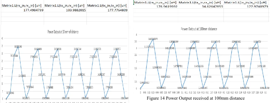
[image:3.595.317.535.391.519.2]Now the distance between the primary and secondary is increased to 30 mm and the simulated mutual inductance is given 103.98 µH and the coupling coefficient is 0.585. The coupling coefficient is very respectable for wireless power transfer. Using the Twin builder the power output is calculated as 33.14 W which is very respectable for charging of a device with a thick outer shell or base.
Figure 9 Magnetic Field between coils at 30mm enclosed in a vacuum box
[image:3.595.40.561.406.789.2]Figure 11 Power Output received at 30mm distance
[image:4.595.46.571.51.252.2]The distance between the primary coil and the secondary coil is further increased up to 100 mm and the coupling coefficient is 0.195. The output power is 3.5W but when the input is adjusted to 3 times the regular input the output is obtained around 35W.
Figure 12 Magnetic Field between coils enclosed in a vacuum box
Figure 13 Lateral closed view of Magnetic Field density
[image:4.595.47.287.354.524.2]Figure 14 Power Output received at 100mm distance
Table 1 Power Output in Secondary coil with respect to distance
Distance
5mm 30mm 100mm
Mutual Inductance 177.47 µH 103.98 µH 34.62 µH
Coupling coefficient 0.9164 0.585 0.195
Output Power 87.8 W 33.14 W 3.5 W
As per the table1 the output power received in the secondary coil having enough power to charge or drive the Office communication systems like Laptops, monitors, mobile phones, printers.
[image:4.595.302.574.518.732.2]The input frequency is varied from 1kHz to 120kHz and the respective resonant capacitance values are calculated and put in the circuit of Twin builder. It can be seen from the figure 15 that input frequency between 20kHz to 30 kHz, the output
Figure 15 Power output Vs Resonant frequency
[image:4.595.46.290.549.729.2]International Journal of Innovative Technology and Exploring Engineering (IJITEE) ISSN: 2278-3075, Volume-8, Issue-9S, July 2019
[image:5.595.303.549.110.263.2]power appears to be maximum, with all the other parameters fixed. So far the simulations were performed with input frequency 40kHz. Now the input frequency is taken as intermediate of 20kHz-30kHz and is 25kHz of resonance frequency. Now the simulations have performed with 25kHz input frequency for same coil parameters with coil distance of 30mm. The simulated mutual inductance is given 103.98 µH and the coupling coefficient is 0.585. The coupling coefficient is very respectable for wireless power transfer.
Figure 16 Magnetic Field between coils at 30mm enclosed in a vacuum box
[image:5.595.47.262.179.309.2]Figure 17 Lateral closed view of Magnetic Field density at 30mm
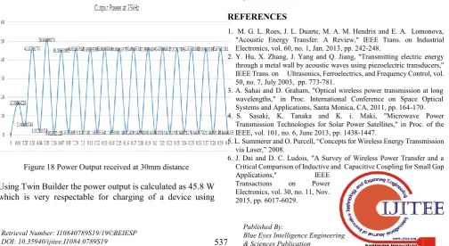
Figure 18 Power Output received at 30mm distance
Using Twin Builder the power output is calculated as 45.8 W which is very respectable for charging of a device using
[image:5.595.47.278.366.514.2]wireless power transfer technique. There is an improvement of 72% in the output power over the previously taken input frequency 40kHz. Hence 25kHz input frequency is better suitable for proposed coil design.
Figure 19 Distance vs Coupling coefficient As per the data from Table 1, distance vs coupling coefficient is plotted and is shown in Figure 19. The coupling coeffiecent between coils descreases as the distance betweenthe coils increases.
IV. CONCLUSION
The simulation analysis of Wireless Power Transfer for office communications has performed using the over Maxwell 3d of Ansys electromagnetic suite. As per the simulation results the output power received in the secondary coil having enough power to charge or transmit the power to the Office communication systems like Laptops, monitors, mobile phones, printers. The simulations were performed at variable distances between transmitter coil and receiver coil as 5mm to 100mm. As per the results it has been observed that the input frequency of primary coil between 20 kHz to 30 kHz, the output power appears to be maximum with all the other parameters fixed. There is an improvement of 72% seen in the output power of secondary coil for 25 kHz input frequency of primary coil over the input frequency of 40 kHz. Hence the 25 kHz input frequency is best suitable for the proposed model of coil parameters.
REFERENCES
1. M. G. L. Roes, J. L. Duarte, M. A. M. Hendrix and E. A. Lomonova, "Acoustic Energy Transfer: A Review," IEEE Trans. on Industrial Electronics, vol. 60, no. 1, Jan. 2013, pp. 242-248.
2. Y. Hu, X. Zhang, J. Yang and Q. Jiang, "Transmitting electric energy through a metal wall by acoustic waves using piezoelectric transducers," IEEE Trans. on Ultrasonics, Ferroelectrics, and Frequency Control, vol. 50, no. 7, July 2003, pp. 773-781.
3. A. Sahai and D. Graham, "Optical wireless power transmission at long wavelengths," in Proc. International Conference on Space Optical Systems and Applications, Santa Monica, CA, 2011, pp. 164-170. 4. S. Sasaki, K. Tanaka and K. i. Maki, "Microwave Power
Transmission Technologies for Solar Power Satellites," in Proc. of the IEEE, vol. 101, no. 6, June 2013, pp. 1438-1447.
5. L. Summerer and O. Purcell, “Concepts for Wireless Energy Transmission via Laser,” 2008.
6. J. Dai and D. C. Ludois, "A Survey of Wireless Power Transfer and a Critical Comparison of Inductive and Capacitive Coupling for Small Gap
Applications," IEEE
Transactions on Power
[image:5.595.49.554.554.830.2]7. G. a. Covic and J. T. Boys, “Inductive Power Transfer,” Proc. IEEE, vol. 101, no. 6, 2013, pp. 1276–1289.
8. N. Tesla, “High frequency oscillators for lectro-therapeutic and other purposes,” in Proc. IEEE, vol. 87, no. 7, 1999, pp. 1282–1292. 9. S. Y. R. Hui, "Magnetic Resonance for Wireless Power Transfer [A Look
Back]," IEEE Power Electronics Magazine, vol. 3, no. 1, March 2016, pp. 14-31.
10. H. A. Wheeler, "Simple Inductance Formulas for Radio Coils," in Proceedings of the Institute of Radio Engineers, vol. 16, no. 10, Oct. 1928, pp. 1398-1400.
11. H. A. Wheeler, "Inductance formulas for circular and square coils," in Proceedings of the IEEE, vol. 70, no. 12, Dec. 1982, pp. 1449-1450. 12. S. S. Mohan, M. del Mar Hershenson, S. P. Boyd and T. H. Lee, "Simple
accurate expressions for planar spiral inductances," in IEEE Journal of Solid-State Circuits, vol. 34, no. 10, Oct 1999, pp. 1419-1424. 13. Kunwar Aditya, Sheldon S. Williamson “Design Guidelines to Avoid
Bifurcation in aSeries–Series Compensated Inductive Power Transfer System IEEE Transactions on Industrial Electronics, vol.66, no.5, May 2019.
AUTHORSPROFILE
Lala Bhaskar received the M.Tech. degree from Guru Gobind Singh Indraprastha University, Delhi, India, in 2008. He is currently working as an Assistant Professor in the Department of Electronics and Communication Engineering, Amity University Uttar Pradesh, Noida, India. He is pursuing his Ph.D. from AIIT, AUUP, Noida and has 10 years of teaching experience, most recently focusing on Wireless Power Transfer Systems, VLSI, Embedded and IoT applications, design and verification using Verilog and System Verilog. He has published more than 10 research papers in international Journals/conferences.
Dr Pradeep Kumar is currently working as an Associate Professor in the Department of Electronics and Communication Engineering, Amity University Uttar Pradesh, Noida, India. He has received his Ph. D. degree from Garhwal University Srinagar (Garhwal) Uttaranchal, India, in 2006. Dr Kumar’s has 14 years of teaching and research experience, most recently focusing on VLSI, microelectronics, device modelling and simulation, design and verification using Verilog and system verilog. He has published more than fifty research papers in national and international Journals/conferences.
![Figure 1 RIPT setup suggested by Tesla[8], [9]](https://thumb-us.123doks.com/thumbv2/123dok_us/8192682.258432/1.595.304.559.578.723/figure-ript-setup-suggested-tesla.webp)
![Figure 3 Physical representation of Archimedean spiral (a) 3-D view [13] (b) Cross-sectional view](https://thumb-us.123doks.com/thumbv2/123dok_us/8192682.258432/2.595.305.549.429.648/figure-physical-representation-archimedean-spiral-view-cross-sectional.webp)