Published By:
Abstract: This paper presents a multi-agent based distributed traffic control model to optimize the traffic signal for multiple intersections. Previous works in the area of traffic signal control suffer from a number of inadequacies, including the use of fixed cycle length, centralized mode of operations and dependency on historical data. Considering these, the aim of this work is to control the traffic signal timings by adjusting the phase sequence in order to minimize the delay in traffic at the intersections. To model the traffic network, a three-tier multi-agent system has been adopted in distributed mode. In addition, a fully actuated signal control algorithm is designed and it utilizes state-space equations to formulate the queue length at the green light phase and red light phase. The proposed model is simulated with SUMO simulator and a comparative analysis has been made between adaptive control method, multi-agent method based on collective learning and multi-agent based fully actuated control method on a similar platform. The results spectacle the proposed traffic control model outperforms that of other existing control methods in all condition; hence it can be deployed to control the tremendous traffic on the road network and to optimize the traffic signal in more effective manner.
Index Terms: Distributed system, Multi-agent, Queue length, Traffic delay, Traffic optimization.
I. INTRODUCTION
In the era of advancement, traffic network optimization is becoming a more complex and challenging task in developing countries because of the rapid development of urbanization construction. The gigantic amount of vehicles on the limited road network is resulting in a slow movement, congestion and traffic jams [1]. The expansion of road infrastructure with the increasing number of vehicles is a simple method to resolve this problem. However, it is not possible because of lack of free space. According to United Nations report, traffic congestion costs 30 bn to the economy and India losses 3% of its GDP (Gross Domestic Product) to road accidents. The above statics implicates that; decrease in congestion will reduce road accidents, increase the economy and accelerate the GDP.
To improve the efficiency of traffic network, intelligent traffic system research is essential, aims to increase the traffic flow on the road network. Optimization of a traffic signal at intersections within the network is the prime goal of the intelligent traffic system.
Revised Manuscript Received on September 05, 2019
Pushpi Rani, Department of Computer Applications, National Institute of Technology Jamshedpur, India; Department of Information Technology, University College of Engineering and Technology, Vinoba Bhave University, Hazribag, Jharkahnd, India
Dilip Kumar Shaw, Department of Computer Applications, National Institute of Technology Jamshedpur, India
.
The optimization of a traffic signal entails minimization of vehicles’ delay and maximization of traffic flow at intersections and this can be accomplished by improving the capability of a traffic signal.
Although, there are an extensive range of previous research within the area of traffic optimization, but these works have several inadequacies. One of the previous inadequacy is the use of historical and off-line data to govern the signal timing at intersections. These methods do not describe the current state of traffic, as traffic pattern does not remain static over all the time. Many of these methods are using either pre-timed operation or semi-actuated operation [2]. They have a fixed cycle length that is not apposite in the current traffic scenario. Second, various existing intelligent traffic control methods are based on a centralized architecture which is not capable to handle large cities having thousands of intersections [3]. Centralized methods highly depend on large communication networks to pass information, failure within the communication lines resulting in substantial degradation of performance. For a huge network system consisting of many intersections, it is computationally difficult to optimize the traffic signals due to expanded complexity. This is the place a multi-agent based distributed control strategy can handle the complexity as proposed in this paper.
Multi-agent technology (MAT) is an augmentation of the agent-based method where every agent is self-governing and it can take care of the control problems dependent on the data gathered without no one else's input [4]. In the meantime, these agents can team up with each other in accomplishing a common aim. In such a way, MAT divides a huge multifaceted framework into some small sub-frameworks that is easy to oversee. MAT possesses communication competence of agents, can explicitly address the collaboration issue among individuals or associations with conflicting objectives. It makes the MAT prevalent in solving complex real-world problems. Therefore, it has been broadly adopted in many areas including railway scheduling [5]-[7], CMM assessment [8], urban land planning [9]. In a traffic network, each intersection maximizes its own throughput and communicates with each other to maximize the network throughput; here MAT is a suitable technology to balance the conflicting requirements of an individual intersection.
The work presented here, has two main contributions to the optimization of traffic signal control. 1) To design a multi-agent based distributed traffic control model. 2) To develop an algorithm based on a fully actuated control method, for the determination of effective signal state. The proposed algorithm is also used to simulate a traffic network; simulation results computed the average delay in traffic. Thereafter, this algorithm is implemented in the proposed distributed traffic
model which increases the robustness of the system.
Multi-Agent Based Traffic Signal Optimization
under Fully Actuated Control
The rest of this paper is organized as follows. A brief summary of related works is presented in section 2. Section 3 describes the proposed method followed by simulation results in section 4. Section 5 provides the concluding remarks on the work done in the paper.
II. RELATEDWORKS
Significant contributions of researchers towards the optimization of the traffic signal are available in the literature. Araghi et al. (2015) have reviewed many computational methods for controlling the traffic signal. They implemented four controllers: Fuzzy logic system, Neural Network, Q-learning and Fixed-time and evaluated the performance for different scenarios [10].
Split, cycle and offset optimization technique (SCOOT) [11] and green link determining (GLIDES) [12] is applied successfully in the number of cities and manage the traffic control system. These systems use the centralized control method to optimize traffic signal timing. RHODES is one of the most popular adaptive traffic control systems based on distributed approach [13]. This system run locally and the neighbors can communicate with each other to maintain the coordination between intersections. Maa et al. (2016), presented multistage stochastic program based on phase clearance reliability. This is an adaptive traffic control approach with fixed cycle length [14].
Another area of research for the optimization and estimation of traffic signal includes artificial intelligence based techniques. Fuzzy logic, Neural Networks, reinforcement learning are the most common artificial intelligence techniques adopted in the traffic controller. Several fuzzy logic signal controllers have been presented by researchers. Most of them are based on fuzzy logic [15]-[18] and some are on type-2 fuzzy logic [19], [20]. These all are based on static rule-base; simple and effective methods for a small network. However, it is difficult to generate a large number of rule-base for multiple and complex intersections. Neural networks based signal controllers are another artificial intelligence based method for traffic control. In this method, a neural network is used to train the network; static traffic data is used for training [21]. The structure is simple, but the model must be retrained if the traffic volume changes. Some researchers applied a decision support system in traffic optimization and developed the traffic signal control, aim to assist human operator in the selection of effective signal state [22]-[24]. Similar to fuzzy logic, these systems also depend on the historical database and need a frequent update with a change in the traffic scenario. The application of reinforcement learning in the optimization of traffic is also highlighted in the previous research works. These approaches generated reward model for state-action pair to allow interaction between the environment and traffic controlling agents [25]. However, these approaches suffered from the use of static traffic data and also require an extensively large number of state-action pair to model the city-sized network.
Multi-agent technology gain popularity since the last few decades and many models has been proposed [26, 27, 28]. Arel et al. used reinforcement learning in multi-agent system for traffic scheduling at intersections. Balaji and Srinivasan adopted Hierarchical multi-agent system and used neuro fuzzy decision system for urban traffic system control.
Abdoos et al. introduced holonic multi-agent system to model the large traffic network and incorporate it with Q-learning method to control the signal.
From previous works, it has been observed that the traffic control method is pre-timed or semi actuated. In the pre-time mode, the cycle length is predefined and will remain fixed, while in the semi-actuated mode the cycle length is fixed for a certain time and vary for the rest of the time. It has been observed that the pre-timed mode of signal control doesn’t use green time effectively. Besides this, majority of multi-agent based system adopted artificial intelligence techniques to split the green time at the intersections. The signal coordination is centralized hence not the robust model. To fill this breach, this paper proposes a distributed model based on multi-agent technology and fully actuated traffic control method.
III. PROPOSEDMETHODOLOGY
The proposed method is divided into two parts; first, a multi-agent based distributed traffic model has been designed, thereafter a fully actuated signal control algorithm is developed and has been assimilated in the designed traffic model.
A. Multi-agent based distributed traffic control model A distributed road traffic model
A road network is represented by a graph where V is a set of nodes and E is a set of edges. In the proposed system it is viewed as a distributed system; there are several intersections (nodes), each have own local memory and have the same goal. Although, each component of the distributed system has its individual needs, therefore, they coordinate with each other to share the common resources. Similar to a distributed system, there are several intersections in the road network. Each intersection has a different infrastructure and traffic scenario, but as a system, they have a common goal of maximizing the traffic flow, therefore; they coordinate with each other to share the signal timing at an intersection.
Architecture of multi-agent system
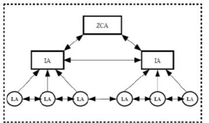
[image:2.595.311.524.591.716.2]The proposed multi-agent system is composed of three components: Zone controller agents (ZCAs), Intersection agents (IAs) and Lane agents (LAs). It has three-layer architecture as shown in Fig. 1.
Published By: Zone controller agents (ZCAs): Zone controller agents, the
highest level agents are the monitoring agents aim to balance the conflicting requirements of an individual intersection. They will communicate with IAs to gain information about their control mechanisms and then regulate these mechanisms to accomplish the goal of global optimization for the unabridged road traffic scheme.
The ZCAs divides the road traffic network into a set of a small network; consisting an adaptable number of IAs and LAs, i.e.; a widespread signal control problem is divided into a set of sub-problems for the lower level layers. Although, the overall performance of the road traffic network is managed by the ZCAs, they do not pact with the signal control mechanism. The ZCA determines the partition for the entire network, considering that each partition is controlled by one ZCA. In this paper, the partition has been done according to the road network architecture. Viz., the intersections on the main road and within the range of 10KM, where coordination among the intersections is highly required form one partition, whereas the other intersections of the side roads are clustered together and form another partition. Similarly, the entire road traffic network is partitioned into a cluster of sub-network. Thus, each partition has some supporting agents (LAs), at least one computational agent (IA), and it is governed by a single monitoring agent (ZCA).
Intersection agents (IAs): Intersection agents are located in the middle layer and determine the signal timing. This is the computational unit of the multi-agent system. The intersection agent can be defined by a 3-tuple IA(ID N, RE,NRL) where,
ID is a unique identification number of that intersection, NRE
is the number of routes entering that intersection and NRL is
the number of routes leaving that intersection. The unique identification number plays a key role to distinguish the intersections by identifying each intersection uniquely in the network. Each intersection follows the fully actuated signal planning mechanism. In the actuated signal control method, the green time has two constituents: actual green time and extended green time. The actual green time is fixed and assured for each intersection whereas, extended green time is optional and depends on the current traffic conditions. The intersection agent executes FASC, described in the next section, before the actual green time has been elapsed, which determine whether the extended green time should be added with the actual green time or not.
Lane agents (LAs): Lane agents are in the lowest layer agents. It works as a supporting unit of the multi-agent system and aims to provide the current traffic status to the neighbor intersection agents. The lane agent can be defined by a 3-tuple LA(ID N N FL, L, I, ) where, ID, is the unique
identification number of the lane agent, NL is the set of all
neighboring lane agents, NI is the set of all neighboring
intersection agents and FL represents the traffic flow direction. Similar to intersection agents, the unique identification numbers of the lane agents specify them distinctively in the network and aim to resolve the ambiguity. All the lane agents can communicate and receive the information from their neighbor lane agents only and transmit the information to their neighboring, both lane agent and intersection agents. The information transmission among the neighbor agents is through communication lines. The lane
agent receives basic traffic information (vehicle speed, traffic flow, traffic volume) from sensors and vehicle detectors placed at the roadside.
Multi-agent based control
[image:3.595.321.530.287.436.2]To implement the multi-agent based control in a distributed manner, assumed that, there are N intersections and each intersection work as an independent agent. In the real traffic, there are various types of intersection and it is classified by the number of links connected at an intersection. It can be a T-shape intersection or cross intersection. The T-shape intersection connects 3 links and the cross intersection connects 4 links. Road network is complex and the intersections are too far from each other, hence it is not possible to govern the entire region of intersection using a single agent. To distinguish the intersections, different agents are placed at T-shaped intersection and cross intersection. T-shaped intersections are governed by lane agents and whereas, cross intersection by intersection agents as shown in Fig. 2.
Fig. 2 A road network with multiple agents
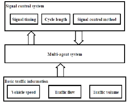
[image:3.595.317.532.486.659.2]The structure of proposed multi-agent based traffic control system is presented in Fig. 3.
Fig. 3 Structure of multi-agent based traffic control system B. Data communication
The communications among the agents are very critical in the proposed method as the system highly depends on the data received from the neighboring agents. Here the continuous transmission of data is required, considering the aforementioned; the designed
traffic model uses both,
bidirectional mode of data transmission.
The communication between lane agents and intersection agents are unidirectional, as the lane agents are supporting agents and send traffic information to the neighboring intersection agents. The transmission between the neighboring lane agents are bidirectional, they send and receive the traffic information reciprocally. Similarly, the traffic information to be transmitted by the lane agent is defined by a 3-tupleTI LA
L T, max,FL
, where, L is the length of the lane, FL is the traffic flow direction andT
maxis the maximum traffic volume which a lane can sustain. It can be evolved as follow:
(1)
Here, L is the length of the lane; l is the average length of vehicles and
is the distance between the vehicles. FL is set to 1 or 0, FL1 represents the traffic flow towards the lane agent and FL0 states that the vehicles are leaving the current lane agent. Similarly, the intersection agents send the traffic information to the neighbor intersection agents and receive the information too, hence follow the bidirectional transmission. Traffic information to be transmitted between the intersection agent is defined by a 3-tuple
, r,
TI IA C G TV includes Cycle length, the Green ratio and the Traffic volume at that intersection. Allthe intersection agents can communicate and receive information from their neighbor intersection agents and lane agents. Based on the information gathered from the neighboring agents, an intersection agent makes their decision. It receives traffic information from the neighbor lane agents and intersection agents. Then, it aggregates all the collected information and applies the FASC algorithm, discussed in the next section, on the aggregated information. This algorithm processes the information and decides accordingly.
The intersection agents will communicate with the Zone controller agents by sending the relevant traffic information (e.g., signal timing, traffic volume, and distance between adjacent intersections) to it. The ZCA will gather this information and test the performance of a multi-agent based traffic system to monitor and control the unabridged system. C. Fully actuated signal control algorithm (FASC) Before enlightening the mechanism of proposed algorithm, it is needed to describe the parameters used in the algorithm. The proposed algorithm is using the following parameters: Parameters
Cycle length (c): It indicates the time of the whole duration including the phases of signal.
Green time (g): It is the time during which the vehicles are allowed to move from the stopped position.
Green ratio (Gr): It is the green time to that of the whole
cycle length and given by (g/c).
Red time (r): It is a part of cycle length, during this stage the vehicles are not allowed to move from the stopped position. Queue length (QLG): Queue length at green light phase.
Queue length (QLR): Queue length at red light phase.
The queue length is an important parameter to describe the traffic state of an intersection. The queue length at time t in green light phase can evolve as
(2)
Here, k is the number of green phase branch.
(3)
( )
gi
Q t
, is the queue length at the onset of the time interval tin the green light phase;
( )
gi
q
t
is the number of vehicles that join the ith queue in thetth time interval;
( )
gi
d
t
is the number of vehicles that depart from the ith queue in the tth time interval;Similarly, the queue length at time t in red light phase can evolves as
(4)
(5)
The aim of this algorithm is to control the traffic light timings by adjusting the phase sequence to maximize the flow of traffic. This is based on a fully actuated control system. In this FASC algorithm, the cycle length is based on the traffic volume and not fixed throughout the day. Consider a scenario, suppose that at the end of green time, the traffic volume at the green light phase intersection is very high compared to the traffic volume at the red light phase intersection. Now, if the signal control method is pre-timed, then it must change at the end of signal timing and present conditions would be ignored. Change in signal phase at this moment, will cause denser traffic at one end of intersection and resulting in the increase of queue length at the green light phase intersection. Therefore, to overcome this problem, before changing the signal phase, observe the difference between queue length at the green light phase and red light phase. If the queue length at the green light phase is greater than the queue length at the red light phase, then increase the green ratio. It would increase the green time at the intersection. But, if every time the queue length at the green light phase is greater than the queue length at the red light phase, then the vehicles at the red light phase will encounter a too high delay resulting in starvation. Hence, there must be a limit to regulate this and put a time limit on the change of the signal phase to prevent starvation. If in two consecutive times, the queue length at the green light phase is greater than the queue length at the red light phase, then change the signal phase, so that the vehicles at the red light phase will get the green time. The sequence of FASC is composed of the following
steps described and
illustrated in Fig. 4. max
L T
l
1
(
1)
k
LG gj
j
Q
Q t
(
1)
( )
( )
( )
gi gi gi gi
Q t
Q t
q
t
d
t
1
(
1)
k
LR rj
j
Q
Q t
(
1)
( )
( )
ri ri ri
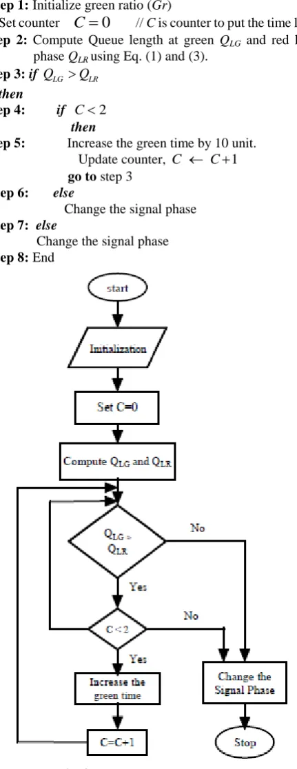
Published By: Step 0: Start
Step 1: Initialize green ratio (Gr)
Set counter
C
0
// C is counter to put the time limit Step 2: Compute Queue length at green QLG and red lightphase QLRusing Eq. (1) and (3).
Step 3: if QLG QLR
then
Step 4: if C2
then
Step 5: Increase the green time by 10 unit. Update counter, C C1 go to step 3
Step 6: else
Change the signal phase Step 7: else
[image:5.595.58.274.65.624.2]Change the signal phase Step 8: End
Fig. 4. Flow chart of FASC algorithm
Step 1 initializes all the input parameters including several vehicles at the intersection during the previous phase, arrival rate, departure rate, green ratio and set the counter to zero. Step 2 keeps track of the number of vehicles arrival and departure at the intersection during the complete cycle to compute the queue length at the green light phase and red light phase. Here equation (2) and (4) are used for the computation of queue length. Afterward, step 3 makes a comparison between the queue lengths computed in step 2, if this condition is true then control goes to step 4, otherwise to step 7 and signal phase has been changed. Step 4 checks the status of the counter, if it is less than 2, then increases the green time
by 10 unit, which increases the green ratio. Thereafter, the counter C is incremented by 1 and control goes to step 3. If the condition in step 4 is false, then control goes to step 6 and signal phase has been changed.
D. An example
Consider an example to show the correctness of FASC algorithm, suppose that the cycle length (c) is set to 120 and green time (g) is 80, so, the green ratio (Gr) is given by 120/80. Now, FASC algorithm is executed, before the green time of the cycle elapsed. It initializes all the parameters and set the counter C to 0 in step 1. If the condition is given in step 3 and step 4 is true, then green time is increased by 10 and the green ratio is 90/120. This process will be repeated if the condition is true again and resulting in a change in green ratio to 100/120. After two consecutive increments in green time, the condition in step 4 ensures the signal to be changed even if the condition in step 3 is true. In this way, the algorithm will always be terminated after two successive executions.
E. FASC in multi-agent based distributed traffic model To implement FASC in multi-agent based distributed traffic model, the sequence of steps to be followed is described below.
Data Collection: This is the first step of the proposed. In this step, the lane agent receives basic traffic information (vehicle speed, traffic flow, traffic volume) from sensors and vehicle detectors placed at the roadside and the individual intersection agent collects the information from their neighboring agents during each cycle phase. Lane agents provide the current status of traffic over the nearby lanes. The intersection agents make available the traffic status on the nearby intersections and receive the current signal status from the signal control system. In this way, the information is gathered from both the lane agents and the intersection agents.
Information Aggregation: After receiving the information from the neighboring agents, the intersection agent aggregates the values to get the total queue length at that intersection in both the green light phase and red light phase. Thereafter, the aggregated information is supplied as an input to the FASC algorithm.
Algorithm evaluation: In the next step, the intersection agent process the inputs received from the previous level and evaluate the FASC algorithm described earlier.
Signal state selection: This is the last step; in this step, the output of an algorithm is sent to the next level. Based on the produced output, the appropriate signal state is selected.
IV. SIMULATIONRESULTS A. Case Study
To test the performance of the proposed method, it is implemented in the urban area of Jamshedpur city. The map of Jamshedpur city has exported from Open Street Map (OSM). Besides, the real world map, microscopic simulator, Simulation of Urban Mobility (SUMO-0.28.0) [29], has been used to generate the road
traffic scenario. The traffic network considered for
intersections and divided into two lanes. The traffic statistics of the simulation area are obtained with the assumption that the arrival of vehicles at the intersections is randomly and following a Poisson distribution.
Additionally, SUMO design the interface discussed above for simulation and MATLAB is used to implement the algorithm.
B. Result discussion
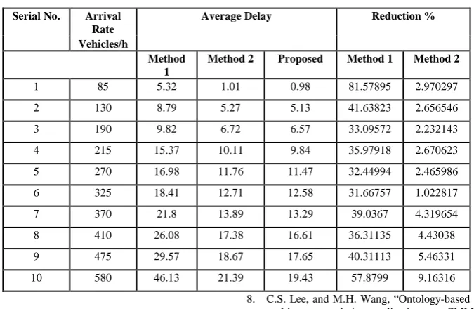
In a real scenario, the traffic volume varies in different hours of a day. Therefore, the practical approach should work smoothly with different traffic volumes. Traffic volume of any network depends on the arrival rates of vehicles. The higher arrival rate of vehicles, results in higher traffic volume. To verify the capability of the proposed method, it is needed to simulate the network with different arrival rates. Henceforth, the designed traffic network has been simulated with adaptive control method (method 1), presented by Maa et al. (2016) [14], multi-agent based method (method 2) presented by Jin and Maa (2018) [30] and the proposed method. By varying the arrival rates, the average delay is computed for each simulation. Here each method is run for 10 times with different arrival rates. Each pair of simulations is executed 10 times to upturn the reliability of results. The minimization of traffic delay resulting in optimization of traffic signal, therefore, average delay in traffic at the intersection is selected as performance measuring parameter. The results presented in Table I show that the proposed method, incur a reduction in traffic delays in compare to method 1 and method 2.
This result shows that in an adaptive control method the traffic delay is gradually increasing and the traffic scenario is getting worst as the arrival rate of vehicles increases. It implies that method 1 is not proficient with higher traffic volume. The average delay computed by method 2 is lesser than method 1 and higher than the proposed method. Although there is a marginal difference between the delay computed by method 2 and the proposed method but the latter outperforms over the former method. The average delay experienced by all the methods with different arrival rates is presented by a graph as shown in Fig. 5. From the figure, method 1 is suffering from a higher delay compared to method 2 and the proposed method. The graph also shows that in method 1 delay increases with a higher rate. The delay experienced by method 2 is closer to the proposed method but there is a slight improvement in the results. The differences in the results are increasing with an increase in arrival rates.
Fig. 5. Average delay in different methods
To prove the superiority of the proposed method, it is compared with two different methods; including, an adaptive control method with a fixed cycle length 200 and hierarchical multi-agent based method. Since the first method is adaptive controlled method with a fixed cycle length, we first compare the proposed method with this method to show the superiority of fully actuated control method over adaptive control method with a fixed cycle length method. Thereafter, it has been compared to hierarchical multi-agent method based on collective learning control. The comparison results show that the proposed method is more reliable than the existing multi-agent based method.
Published By: Table I Simulation results
Serial No. Arrival Rate
Average Delay Reduction %
Vehicles/h
Method 1
Method 2 Proposed Method 1 Method 2
1 85 5.32 1.01 0.98 81.57895 2.970297
2 130 8.79 5.27 5.13 41.63823 2.656546
3 190 9.82 6.72 6.57 33.09572 2.232143
4 215 15.37 10.11 9.84 35.97918 2.670623
5 270 16.98 11.76 11.47 32.44994 2.465986
6 325 18.41 12.71 12.58 31.66757 1.022817
7 370 21.8 13.89 13.29 39.0367 4.319654
8 410 26.08 17.38 16.61 36.31135 4.43038
9 475 29.57 18.67 17.65 40.31113 5.46331
10 580 46.13 21.39 19.43 57.8799 9.16316
CONCLUSIONS
This paper presented a fully actuated traffic control algorithm based on multi-agent technology. The fully actuated traffic control algorithm can generate an effective signal plan and MAT has been adopted to implement the algorithm in a distributed manner. The proposed method can handle large network having hundreds of intersections, hence increase the robustness of the system. To examine the performance of the proposed method, SUMO simulator is used and road traffic scenario has been generated on the real road map of Jamshedpur city. The performance of proposed method has compared to adaptive control method with a fixed cycle length and multi-agent method based on collective learning on a similar network. The simulation results exhibit that the proposed method is more effective than the existing methods
.
REFERENCES
1. F. Motawej, R Bouyekhf, and A. EL. Moudni, “A note on Artificial Intelligence techniques and Dissipativity-based Approach in Traffic Signal Control for an Over-Saturated Intersection”, Proceedings of the 18th World Congress, The International Federation of Automatic Control Milano (Italy) August 28 - September 2, pp. 10721–10726, (2011).
2. S. Feng, Y. Ci, L. Wu, and F. Zhang, “Vehicle delay estimation for an isolated intersection under actuated signal control”, Mathematical Problems in Engineering, pp. 1-7, (2014).
3. J. Sanchez, M. Galan, and E. Rubio, “Applying a traffic lights evolutionary optimization technique to a real case: ‘‘Las Ramblas’’area in Santa Cruzde Tenerife”, IEEE Transactions on Evolutionary Computation, 12(1), pp. 25–40, (2008).
4. M. Xu, K. An, L. H. Vu, Z. Ye, J. Feng, and E. Chen,“Optimizing multi-agent based urban traffic signal control system”, Journal of Intelligent Transportation Systems, pp. 1-13, (2018).
5. A.A. Belousov, A.A. Goryachev, P.O. Skobelev, and M.E. Stepanov, “A multi-agent method for adaptive real-time train scheduling with conflict limitations”, Int. J. of Design & Nature and Ecodynamics, 11(2), pp. 116–126, (2016).
6. P. Dalapati, A.J.Singh, A. Dutta, and S. Bhattacharya, “Multi agent based railway scheduling and optimization”, TENCON 2014, 2014 IEEE Region 10 Conference (2014).
7. P. Dalapati, A.J.Singh, and A. Dutta, “Multi agent based algorithmic approach for fast response in railway disaster handling”, IEEE/WIC/ACM International Conference on Web Intelligence and Intelligent Agent Technology (WI-IAT). 316-319 (2016)
8. C.S. Lee, and M.H. Wang, “Ontology-based computational intelligent multi-agent and its application to CMMI assessment”, Applied Intelligence, pp. 203-219, (2009).
9. D.C. Parker, S. M. Manson, M.A. Janssen, M..J Hoffmann, and P. Deadman, “Multi-agent systems for the simulation of land-use and land-cover change: a review. Annals of the Association of American Geographers, 93(2), pp. 314–337, (2003).
10. S. Araghi, A. Khosravi, and D. Creighton, “A review on computational intelligence methods for controlling traffic signal timing”, Expert Systems with Applications, 42, pp. 1538–1550, (2015).
11. P.B. Hunt, D.I. Robertson, R.D. Bretherton, and R.I. Winton, “SCOOT—ATraffic Responsive Method of Coordinating Signals”, Laboratory Report 1014. Transport and Road Research Laboratory, Crowthorne, Berkshire, U.K. (1981).
12. C.K. Keong, "The GLIDE system—Singapore's urban traffic control system", Transp. Rev. 13(40), pp. 295-305 (1993).
13. P. Mirchandani, and L. Head, “A real-time traffic signal control system: Architecture, algorithms, and analysis”, Transportation Research Part C: Emerging Technologies. 9, pp. 415–432, (2001).
14. W. Maa, K. An, and H.K. Lo, “Multi-stage stochastic program to optimize signal timings under coordinated adaptive control”, Transportation Research Part C, 72, pp. 342–359, (2016).
15. E. Azimirad, N. Pariz, and M.B.N. Sistani, “A novel fuzzy model and control of single intersection at urban traffic network”, IEEE Systems Journal, 4(1), pp. 107–111, (2010).
16. Y.S. Murat, and E. Gedizlioglu, “A fuzzy logic multi-phased signal control model for isolated junctions”, Transportation Research Part C: Emerging Technologies, 13, pp. 19–36, (2005)
17. J. Niittymaki, and E. Turunen, “Traffic signal control on similarity logic reasoning”, Fuzzy Sets and Systems, 133, 109–131, (2003).
18. L. Zhang, H. Li, and P. Prevedouros, “Signal control for oversaturated intersections using fuzzy logic”, Transportation and development innovative best practices, pp. 179–184, (2008).
19. P. Balaji, and D. Srinivasan, “Type-2 fuzzy logic based urban traffic management”, Engineering Applications of Artificial Intelligence, 24, pp. 12–22, (2011).
20. Y. Bi, D. Srinivasan, X. Lu, Z. Sun, and W. Zeng, “Type-2 fuzzy multi-intersection traffic signal control with differential evolution optimization”, Expert Systems with Applications, 41, pp. 7338–7349, (2014).
21. W. Wei, and Y. Zhang, “FL-FN based traffic signal control”, Proceedings of the IEEE International Conference on Fuzzy Systems, FUZZ-IEEE ’02. pp. 296–300, (2002).
22. K. Almejalli, K. Dahal, and M. Hossain, “Real time identification of road traffic control measures”, In: Advances in Computational Intelligence in Transport, Logistics, and Supply Chain Management. Studies in Computational Intelligence, 144, pp. 63–80, (2008). 23. K. Almejalli, K. Dahal, and M. Hossain, “An intelligent multi-agent
approach for road traffic management systems”, 18th IEEE International Conference on
24. B.D. Schutter, S.P. Hoogendoorn, H. Schuurman, and S. Stramigioli, “Multi-agent case-based traffic control scenario evaluation system”, Proceedings of the IEEE 6th International Conference on Intelligent Transportation Systems, pp. 678–683, (2003).
25. M. Wiering, J. Vreeken, J. VanVeenen, and A. Koopman, “Simulation and optimization of traffic in a city”, Intelligent Vehicles Symposium, IEEE. 2004, pp. 453–458, (2004).
26. M. Abdoos, N. Mozayani, and A.L. Bazzan, “Holonic multi-agent system for traffic signals control”, Engineering Applications of Artificial Intelligence, 26, pp. 1575–1587, (2013)
27. Arel, C. Liu, T. Urbanik, and A.G. Kohls, “Reinforcement learning-based multi-agent system for network traffic signal control”, IET Intelligent Transport Systems”, 4(2), pp. 128 – 135, (2010). 28. P.G. Balaji, and D. Srinivasan, “Multi-agent system in urban traffic
signal control”, IEEE Computational Intelligence Magazine, 5, pp. 43–51, (2010).
29. Anonymous SUMO Traffic Simulator. http://sumo.sourceforge.net (2011).
30. J. Jin, and X. Maa, “Hierarchical multi-agent control of traffic lights based on collective learning” Engineering Applications of artificial Intelligence, 68, pp. 236–248, (2018).
AUTHORSPROFILE
Pushpi Rani received her MTech in Computer Science and Engineering from the Jaypee University of Engineering and Technology, Guna, India in 2012. She is pursuing her PhD in Computer Applications from the National Institute of Technology Jamshedpur, India and currently working as an Assistant Professor in the Department of Information technology, University College of Engineering and Technology, VBU, Hazaribag, Jharkahnd, India. Her area of research interests includes traffic modelling, network optimization and I/O efficient algorithm.
![3 Methyl 1H pyrrolo[2,1 c][1,4]oxazin 1 one](data:image/gif;base64,R0lGODlhAQABAIAAAP///wAAACH5BAEAAAAALAAAAAABAAEAAAICRAEAOw==)