International Journal of Innovative Technology and Exploring Engineering (IJITEE) ISSN: 2278-3075, Volume-9 Issue-2, December 2019
Abstract: Modular multi level convertor based UPFC (MMC-UPFC) has become one amongst the foremost rising convertor typologies for medium & high-powered applications. In the last years, outstanding researches are done concerning to Transmission congestion and voltage profile management victimization MMC-UPFC. Thus, standard construction convertor UPFC has been a major topic for each industrial applications and tutorial surveys. In this paper, an outline of the ability circuit analysis and operation principle of the standard construction of MMC-UPFC topology is mentioned. Totally different sub-module typologies are mentioned. Then, advantage sides of the MMC-UPFC which of application areas is reviewed. The proposed technique additional appropriate to avoids Transmission congestion & additionally for higher voltage profile management than previous ways, The proposed system used for MMC-UPFC better improvement of voltage profile and effective congestion relief also the entire function a promising answer for sensible applications, particularly once the quantity of sub-modules is fairly high. Simulation and experimental results verify the effectiveness of the proposed
Keywords: Standard construction structure, voltage profile management, Transmission congestion, Modular Multilevel Converter UPFC (MMC-UPFC), sub-module, topology.
I. INTRODUCTION
Transmission congestion occurs as present is insufficient transmission capability in the direction of at once accommodate every wishes in place of transmission use surrounded by a region. Historically, vertically integrated utilities managed this proviso not later than constraining the money-making assassinate of generators by means of the objective of ensuring guarantee also reliability of their specific and/or neighboring systems. Emotional energy business reformation has stirred cohort investment moreover operations decisions interested in the competitive marketplace bar has gone transmission because a communal store at home the in harmony environment. This addition of competitive making as a consequence in harmony transmission makes congestion management difficult. The sweat is compounded before increases during the sum of congestion resultant commencing augmented trade transactions afterward the family member decline in the sphere of the sum of transmission.
Revised Manuscript Received on December 05, 2019.
Mallavolu Malleswararao, Research Scholar, R.M.K. Engineering College,ANNA University, Chennai [email protected]
Dr GEETHA RAMADAS, Professor& HOD EEE,R.M.K Engineering College,ANNA University, [email protected]
Transmission capacity, family member en route for ultimate load, has been declining here completely regions of the U.S. meant for terminated a decade. This decline is probable on the road to continue. Congestion occurs continuously the exciting transmission regularity while flows of electricity diagonally a portion of the organization are controlled otherwise constrained beneath most wanted levels. The word “transmission constraint”1 refers both near a member of paraphernalia otherwise an operational regulate compulsory near shelter reliability to restricts these flows, or else on the way to be short of passable transmission amount near present projected contemporary sources of production not including violating reliability rules. Congestion in the sphere of the transmission scheme canister engages in undesirable consequences: it preserve perimeter the surge of low-cost license near suffer demand; hold back the achievement of municipal strategy goals, or else drawn fashion reliability concerns.
[image:1.595.306.548.494.600.2]Congestion management schemes worn nowadays experience denial impacts by the side of energy markets, such the same as disruptions then pecuniary penalties, less than selected conditions. en route for diminish these concerns an assortment of congestion management methods possess been proposed, together with regard to kill as a consequence cut of scheduled energy transmission. Indoors the rationalized thrilling energy engineering environment, up-to-the-minute congestion management approaches are self urbanized with the aim of strive on the way to do the beloved step of reliability although at the bottom of rivalry during the mass supremacy market.
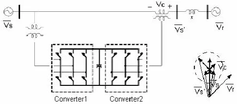
Figure 1: Conventional configuration of UPFC
Figure 2: Conventional equivalent model of UPFC
Transmission Congestion& Voltage Profile
Management using Modular Multi Level UPFC
Conventional UPFC Capabilities:
May control voltage, impedance, and angle Impacts active and reactive power flow in line Increase transmission line capacity
Direct power flow along selected lines Powerful system oscillation damping Voltage support and regulation
Control of active and reactive power flow at both sending- and receiving-end
Modular structure device based mostly unified power- flow controller (MMC-UPFC) is in a position to work underneath unbalanced grid conditions with isosceles element decoupling. However, the constraint of voltage limit of UPFC isn't thought of and no protection schemes are investigated to shield UPFC from over-modulation underneath unbalanced grid condition. To unravel this drawback, this paper proposes the cascaded management theme for MMC-UPFC supported voltage limit management and isosceles element decoupling to balance the ac current of conductor. With applicable electrical device connections for MMC-UPFC, the negative- and zero-sequence currents are suppressed by the corresponding inner current loops. Considering the voltage limit of MMC, the operative ranges of UPFC-MMC underneath balanced and unbalanced grid conditions are investigated in each mathematical derivation and purpose scanning ways. The results art delineated and analyzed in 3-D vision. Supported the analysis of operative regions, the voltage limit management is planned to shield MMC from over-modulation and to maximize the manageable region underneath unbalanced grid conditions. Finally, the ultimate cascaded management structure is made.
II. ADVANTAGESIDESOFMMC:
In comparison with alternative structure convertor structures, the most advantageous of the standard structure convertor are often summarized as in below [6]:
1. Modularity and creating it straightforward to scale in any voltage level by mistreatment cascaded structure,
2. Higher potency. Due to low change frequency, 3. Low doctorate performance. Because of use several sub modules within the arm,
4. High dependableness. Because of use redundant sub modules within the event of sub module failure,
5. Absence of AC filters and DC link capacitors. Because of all the sub modules share the common DC link.
2.1 Application Areas of MMC:
HVDC systems are often mentioned one in every of the appliance areas of the MMC [7, 8]. Because of reduced filter size and low change frequency in every cell, MMC has been taken a big role in HVDC systems rather than a pair of or three level converters.
Medium voltage motor drives is one in every of the opposite application areas of the MMC [9, 10]. Chiefly, the most purpose of the studies relating to Motor Drive applications is to search out an answer of the massive ripple magnitude of the SM electrical device voltages at low frequencies [11].
2.2 Power Quality applications area unit one in every of the opposite application areas of the MMC which are often listed as follows:
MMC based mostly STATCOM [12],
MMC based mostly shunt active power filter [13], MMC based mostly unified power flow controller [14]. Management Structures of the MMC
2.3 Control structures are often explicit because the most advanced a part of the MMC. Chiefly, management structures are often classified as follows:
1. Active and Reactive power management of the MMC 2. DC link management of the MMC
3. Current management of the MMC
4. Electrical device voltage equalization of the MMC 2.4 Operating modes of MMC-UPFC:
1. VAR management Mode:
The reference input is associate inductive or electrical phenomenon volt-ampere request. 2.5 Automatic Voltage management Mode:
The shunt electrical converter reactive current is mechanically regulated to keep up the transmission Vline at the purpose of association to a reference price. For this mode of management, voltage feedback signals area unit obtained from the causing finish bus feeding the shunt coupling electrical device
3. Direct Voltage Injection Mode:
The magnitude and point in time area unit the reference inputs of the series volta
4. Phase Angle Shifter Emulation mode:
The reference input is part displacement between the causing finish voltage and also the receiving finish voltage
5. Line reactance Emulation mode:
The reference input is associate electrical resistance price to insert nonparallel with the road electrical resistance
6. Automatic Power Flow management Mode:
The reference inputs area unit values of P and alphabetic character to keep up on the cable despite system changes.
3. Significance contributions of this paper:
The investigation of MMC-UPFC for Transmission Congestion Relief
Optimization of inequality constraints to obtain optimal sizing of DG
units
sin
S R
SR
V V
P
X
R S
International Journal of Innovative Technology and Exploring Engineering (IJITEE) ISSN: 2278-3075, Volume-9 Issue-2, December 2019
Simulation model of proposed system on IEEE -30 bus system
Performance evaluation of MMC-UPFC in
combination with Computing Techniques
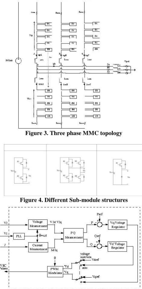
3.1 General Aspects of Modular Multi Level convertors: Three part grid connected standard construction convertor topology is shown in Figure one. A part leg of the MMC is consisted of 2 arms that square measure higher arm and lower arm. every arm has N identical series connected of the sub modules or cells with cascaded structure with Associate in Nursing arm electrical device, Larm Associate in Nursingd an arm resistance, Rarm .Thus; N+1 level MMC are often obtained. Arm electrical device is employed for eliminating the fault currents within the convertor. Arm resistance ought to be selected as low as potential because of convertor power losses [3]. Every sub module of the MMC are often consisted of various circuit structures and a few of the samples of the sub module structures square measure illustrated in Figure a pair of. Considering half-bridge primarily based sub module, the structure is created a capacitance and 2 IGBTs with anti-parallel diodes. However, full-bridge primarily based sub module structure is consisted of a capacitance and 4 IGBTs with anti-parallel diodes. One-way cell circuit structure is that the different one that is created a capacitance and one IGBT with anti-parallel diode for the face t |top |top side |upside| side face} otherwise just one diode while not IGBT for the lower side [4].
Sub modules square measure inserted or bypassed betting on the change positions in every half-bridge circuit. 2 switches add complementary approach otherwise result in contact condition. Once the higher switch is ON and therefore the lower switch is OFF, sub module is inserted within the arm. Thus; the terminal voltage of the sub module is adequate to the capacitance voltage, VC. If the higher
[image:3.595.309.545.50.530.2]Switch is OFF and therefore the lower switch is ON position, sub module is bypassed within the arm. Therefore; the terminal voltage of the sub module is adequate to zero. Betting on the arm current direction, sub module capacitance voltages square measure affected. If the arm current direction is positive, sub module capacitances square measure charged otherwise capacitor voltages square measure discharged. Considering the change states and direction of the arm current, terminal voltage of the sub module capacitance and charge/discharge standing square measure indicated in Figure three [5].
Figure 3. Three phase MMC topology
Figure 4. Different Sub-module structures
Figure 5: Simplified Series Converter Control System
III. SIMULATIONMODELOFTESTSYSTEM:
Figure: 7 Structure of the simulation network
Line
To R(pu) XL(pu)
From
Index
1 2 0.00243 0.05 1
2 1 3 0.00102 0.26
3 2 3 0.01474 0.17
4 2 4 0.01474 0.16
3.1 Performance Evaluation of MMC-UPFC:
From To Congestion Congestion
Line
without with
MMC-UPFC MMC-UPFC
1 1 2 84% 62%
2 1 3 41% 22%
3 2 3 23% 8%
4 2 4 24% 22%
3.2 Performance Evaluation of MMC-UPFC:
Time [s] Pset1 [p.u.] Pset2 [p.u.] Pset3 [p.u.]
0 0.1 0.1 0.1
20 1.01 0.1 0.1
40 1.01 1 0.1
70 1.01 1 1.01
120 0.1 1.01 1.01
140 0.1 0.1 1.01
160 0.1 0.1 0.1
[image:4.595.54.280.333.543.2]
Table 3.3The simulation sequence in the example simulation
The feeder voltage limits within the simulation square measure set to zero.95-1.01p.u
3.1 SIMULATION:
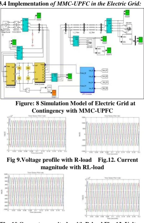
The simulation we performed with the software MATLAB / SIMULINK first assume that the electric network gets a disruption (short-circuit) (Fig 9) and second, implement the MMC-UPFC with the network and see its influence Fig (19).
[image:4.595.307.545.364.732.2]3.4 Implementation of MMC-UPFC in the Electric Grid:
Figure: 8 Simulation Model of Electric Grid at Contingency with MMC-UPFC
Fig 9.Voltage profile with R-load Fig.12. Current magnitude with RL-load
International Journal of Innovative Technology and Exploring Engineering (IJITEE) ISSN: 2278-3075, Volume-9 Issue-2, December 2019
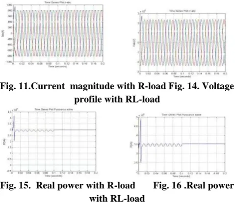
Fig. 11.Current magnitude with R-load Fig. 14. Voltage profile with RL-load
Fig. 15. Real power with R-load Fig. 16 .Real power with RL-load
IV. CONCLUTION:
Transmission Congestion& voltage profile management is a vital issue within the regulated and reregulated setting of power systems. Congestion ought to be mitigated so as to use the utmost power transfer capability of transmission networks. It’s acknowledged that Multi level FACTS technology will management voltage magnitude, point and line electrical phenomenon clearly. Mistreatment these devices could spread the load flow related to control bus voltages. Therefore, it's worthy to research the performance of MMC-UPFC controller on the congestion management.
MMC-UPFC is that the main commercially obtainable the most effective FACTS controllers. This paper presents implementation MMC-UPFC work out the best location and capability of those devices. The planned methodology is utilized incorporating dimensional serialization valuing mechanism. Case studies and therefore the obtained results show the effectiveness of the instructed criterion considerably.
REFERENCES:
1. J. Rodriguez, S. Bernet, B. Wu, J. O. Pontt, and S. Kouro, “Multi- level voltage-source-converter topologies for industrial medium-voltage drives,” IEEE Trans. Ind. Electron., vol. 54, no. 6, pp. 2930–2945, Dec. 2019.
2. S. Kouro, M. Malinowski, K. Gopakumar, J. Pou, L. G. Franquelo, B. Wu,
J. Rodriguez, M. A. Pe´rez, and J. I. Leon, “Recent advances and industrial applications of structure converters,” IEEE Trans. Ind. Electron., vol. 57, no. 8, pp. 2553–2580, Aug. 2018.
3. S. S. Fazel, S. Bernet, D. Krug, and K. Jalili, “Design and compari- son of 4-kV neutral-point-clamped, flying-capacitor, and series-connected H-bridge structure converters,” IEEE Trans. Ind. Appl., vol. 43, no. 4, pp. 1032–1040, Jul./Aug. 2017.
4. J. Pou, R. Pindado, and D. Boroyevich, “Voltage-balance limits in four- level diode-clamped converters with passive front ends,” IEEE Trans. Ind. Electron., vol. 52, no. 1, pp. 190–196, Feb. 2018. 5. S. B. Monge, S. Alepuz, J. Bordonau, and J. Peracaula, “Voltage
leveling management of diode-clamped structure converters with passive front-ends,” IEEE Trans. Power lepton., vol. 23, no. 4, pp. 1751–1758, Jul. 2018.
6. B. P. McGrath and D. G. Holmes, “Enhanced voltage leveling of a flying electrical device structure convertor victimization section disposition (PD) modulation,” IEEE Trans. Power lepton., vol. 26, no. 7, pp. 1933–1942, Jul. 2016..
7. J. Wang and F. Z. Peng, “Unified power flow controller victimization the cascade structure electrical converter,” IEEE Trans. Power lepton., vol. 19, no. 4, pp. 1077– 1084, Jul. 2015.
8. A. Lesnicar and R. Marquardt, “An innovative standard structure con- verter topology appropriate for a large power vary,” given at the IEEE Power school Conf., Bologna, Italy, 2016.
9. Y. Yamina and S. M. Shahidehpour, “Congestion management coordination in the deregulated power market”, Elect. Power Syst. Res., vol. 65, no. 2, pp. 119–127, May 2003.
10. F. Capitanescu and T. V. Cutsem, “A unified management of congestions due to voltage instability and thermal overload”, Elect. Power Syst. Res., vol. 77, no. 10, pp. 1274–1283, Aug. 2007. 11. C. N. Yu and M. Ilic, “Congestion clusters based markets for
transmission management”, in Proc. IEEE Power Eng. Soc. Winter Meeting, New York, Jan. 1999, pp. 1–11.
12. A.Kumar, S. C. Srivastava, and S. N. Singh, “A zonal congestion management approach using ac transmission congestion distribution factors”, Elect. Power Syst. Res., vol. 72, pp. 85–93, 2004.
13. Kumar, S. C. Srivastava, and S. N. Singh, “A zonal congestion management approach using real and reactive power rescheduling”, IEEE Trans. Power Syst., vol. 19, no. 1, pp. 554–562, Feb. 2004. 14. S. Nayak and M. A. Pai, “Congestion management in restructured
power systems using an optimal power flow framework”, M.S. thesis, Univ. Illinois, Urbana-Champaign, 2002, pp. 12–17.
15. B. K. Talukdar, A. K. Sinha, S. Mukhopadhyay, and A. Bose, “A computationally simple method for cost-efficient generation rescheduling and load shedding for congestion management”, Int. J. Elect. Power Energy Syst., vol. 27, no. 5, pp. 379–388, Jun.–Jul. 2005. 16. Yesuratnam and D. Thukaram, “Congestion management in open
access based on relative electrical distances using voltage stability criteria”, Elect. Power Syst. Res., vol. 77, pp. 1608–1618, 2007.
AUTHORSPROFILE
M Malleswararao Currently working as “Research Scholar”at R.M.K Engineering College, Anna University, Chennai. He has received His B.Tech & M.Tech completed from JNTU Kakinada & he has published papers on power quality, FACTS controllers ect