Int. J. Electrochem. Sci., 7 (2012) 11001 - 11010
International Journal of
ELECTROCHEMICAL
SCIENCE
www.electrochemsci.orgEffect of Sb
2O
3Modification on Electrochemical Performance of
LiMn
2O
4Cathode Material
Yulin Ma, Yunzhi Gao, Pengjian Zuo, Xinqun Cheng, Geping Yin*
School of Chemical Engineering and Technology, Harbin Institute of Technology, Heilongjiang 150001, PR China
*
E-mail: [email protected]; [email protected]
Received: 18 September 2012 / Accepted: 10 October 2012 / Published: 1 November 2012
Sb2O3-coated LiMn2O4 is prepared by chemical precipitation method to improve the cycling stability
of LiMn2O4. The uncoated and Sb2O3-coated LiMn2O4 materials are characterized by the X-ray
diffraction (XRD), Transmission electron microscope (TEM) and X-ray photoelectron energy spectrum (XPS). The results indicate that the crystal structure of LiMn2O4 is not affected by the Sb2O3
coating but lattice constant has changed, and most Sb2O3 coat on LiMn2O4 surface. Electrochemical
test shows that Sb2O3-coating could improve the cycling performance of LiMn2O4. At room
temperature, the capacity retention of 2.0 wt. % Sb2O3-coated material is 93.5% after 60 cycles while
that of the bare sample is only 86.3%. Electrochemical impedance spectroscopy (EIS) demonstrates that the improved performance of the Sb2O3-coated LiMn2O4 is due to suppress the augment of charge
transfer resistance during cycling, which indicates that the coating decreases the surface reaction between cathode and electrolyte. Data from TG-DSC studies show that the thermal stability of the surface modified LiMn2O4 electrode is improved.
Keywords: Lithium ion battery, LiMn2O4 cathode, Surface modification, Coatings.
1. INTRODUCTION
In recent years, the demand for power batteries with higher energy and power capability becomes urgent as the decrease of worldwide energy. Lithium ion batteries are considered as the promising candidate for the future mobile energy supply. Concerning cathode materials of lithium ion batteries, spinel LiMn2O4 has been the attractive candidate for electric vehicles due to the cheap,
abundant, and environmental friendly features. However, LiMn2O4 displays fast capacity fading during
electrochemical oxidation of the organic electrolyte at the charged state. It is generally thought that the most important reason was the dissolution of Mn ions [5-8]. The dissolution can be attributed to the HF generated during cycles in LiFP6-based electrolyte. On the other hand, safety issue is one of the
biggest barriers for the development of large-sized lithium-ion batteries,so the materials must have higher safety.
To improve the cycling performance of LiMn2O4, much attention has been focused on surface
coating with metal oxides, such as Li2O3 [9], MgO[10], Al2O3[11], ZnO[12], Co3O4[13], ZrO2[14],
CeO2[15] and TiO2[16]. After coating, the coating layer can reduce the contact area of LiMn2O4
electrode/electrolyte interface and partly suppress the dissolution of the Mn ions from the spinel into the electrolyte. Furthermore, the phase transition during charge-discharge process was suppressed and the lattice distortion of the spinal LiMn2O4 especially at higher temperature was reduced. Recently,
Sb2O3 is reported to be able to improve the electrochemical performance and thermal safety of
Li1.1CoO2[17]. Nevertheless, the modified LiMn2O4 by Sb2O3 has not been reported. In addition, Sb2O3
is a commonly used flame retardant material. Thus, we hope that the Sb2O3 modification not only
improve the cycling performance but also improve the safety of materials.
In this paper, Sb2O3 is coated on the surface of LiMn2O4 powders by chemical precipitation
method. The effect of Sb2O3 coating on the electrochemical performance at the room and elevated
temperatures is investigated and the mechanism of improved performance is discussed.
2. EXPERIMENTAL
2.1 Synthesis of Sb2O3-coated LiMn2O4
LiMn2O4 was prepared by calcining a stoichiometric mixture of lithium carbonate, electrolytic
manganese dioxide at 750°C for 12 h in air, followed by slow cooling to the ambient temperature. The precursor of Sb2O3-coated LiMn2O4 material was synthesized by dropping the ethanol solution of
antimony trichloride the buffer solution made of sodium hydroxide, triethanolamine and LiMn2O4
powder. The precursor was vacuum dried under 150°C to obtain the Sb2O3-coated LiMn2O4 material.
The expected amounts of Sb2O3 were about 1, 2 and 3.0 wt.% of the LiMn2O4 powders.
2.2 Characterization of Sb2O3-coated LiMn2O4
To investigate the crystal structure, the prepared powder was analyzed by Powder X-ray diffraction (XRD) method using a D/Max-rB diffract meter equipped with Cu Kα radiation in the range of 2θ = 10-90° and the step size was 0.02°. The surface morphologies of the pristine and Sb2O3
-coated powder were observed by transmission electron microscopy (TEM, HITACHI S-7650). The surface properties of the pristine and Sb2O3-coated LiMn2O4 were analyzed by X-ray photoelectron
The thermal stability of LiMnO2 powder was investigated by differential scanning calorimetry
combined with thermogravimetry (STA449F3, Netzsch). The cells were pre-cycled for three cycles with 0.1mA/cm2 to reach a stable capacity level and the cycling was interrupted when the cells were charged to a fully intercalated state (4.3V). Then the charged cells were disassembled in a glove box. The test powder was scraped from electrode after remove the electrolyte. A given amount of fresh electrolyte solution and test electrode powder was sealed in a hermetic pan. All of the experiments above were conducted under an argon atmosphere. The pan was heated from room temperature to 400 °C at 5°C min-1
.
2.3 Electrochemical measurements of Sb2O3-coated LiMn2O4 cathode materials
The cathode electrodes with a diameter of 1.4 cm were prepared by mixing active material, acetylene black and polyvinylidene fluoride (PVDF) (8:1:1, by weigh) dissolved in N-methylpyrrolidnone (NMP) to form slurry, which was then coated on Al foil and dried at 120 °C for 14 h. The pure Sb2O3 electrode was prepared with the similar method of LiMn2O4 electrode in order to
investigate the activity of the Sb2O3. The 2025-type coin cells were assembled in a glove box filled
with high pure argon. A metal lithium foil and a solution of 1.0mol/L LiPF6 EC: DEC: DMC (1:1:1)
were used as the anode and the electrolyte, respectively. The charge-discharge tests of the cells were tested between 3.0V and 4.30 V (at 0.2C) on a battery testing system (Neware BTS) at 25°C and 55°C. The cyclic voltammetry (CV) tests were performed on a CHI604B electrochemical workstation with a scan rate of 0.5 mV s-1. The electrochemical impedance spectroscopy (EIS) analysis was also carried out on CHI604B electrochemical workstation using a tri-electrode cell to investigate the variation of cell resistances at different cycle stages. The tests were performed in the frequency range of 100 kHz to 0.01Hz using a voltage vibration of 5mV.
3. RESULTS AND DISCUSSION
Fig. 1 shows the X-ray diffraction patterns of pristine LiMn2O4 and Sb2O3 coated LiMn2O4. No
obvious difference is detected in X-ray diffraction patterns of pristine and Sb2O3-coated LiMn2O4. All
compounds are identified as well-defined single phase products in the face-centered cubic spinel structure with an Fd3m space group, in which the lithium-ions occupy the tetrahedral (8a) sites and metal ions reside at the octahedral (16d) sites. This suggests that the crystal structure of LiMn2O4 is not
affected by the Sb2O3 coating. The absence of Sb2O3 phases in the entire range of the diffraction
patterns may be due to the very low concentrations of antimony. However, there is a slight decrease in the lattice constant of 8.225, 8.223, 8.219 and 8.212, corresponding to the 0%, 1%, 2%, and 3% Sb2O3
coated LiMn2O4, respectively. According to Zhan [17], Sb can dope into the Li1.1CoO2 by replacing Co
and retain the spinel structure α-NaFeO2 type structure. In addition, Guo [18]reported that the lattice
constant of LiNi0.5Co0.25Mn0.25O2 was slightly smaller than those for the ZnO2-coated
in this material and the solid solution layer of Li-Ni-Co-Mn-Zn-O was formed on the surface of LiNi0.5Co0.25Mn0.25O2 sample. The similar surface reactions happen in the TiO2-coated LiMn2O4 [16]
and the Al2O3-coated LiCoO2[19]. In this experiment, the radius of Sb3+ (0.076nm) is smaller than that
of Mn2+ (0.080nm). Therefore, we propose that antimony maybe doped into the spinel LiMn2O4 by
replacing Mn and retained the spinel structure, which means a little solid spinel compound of LiSbxMn2-xO4 formed on the surface of spinel LiMn2O4 during the synthetical process and caused the
shrinkage of the lattice.
0 30 60 90
(d) in te n si ty ( a .u .)
2/ degree
[image:4.596.149.427.218.436.2]( 5 3 3 ) ( 4 4 0 ) ( 5 3 1 ) ( 5 1 1 ) ( 3 3 1 ) ( 4 0 0 ) ( 2 2 2 ) ( 3 1 1 ) ( 1 1 1 ) ( 7 1 1 ) ( 4 4 4 ) ( 6 2 2 ) (c) (a) (b)
Figure 1. XRD patterns of 0 % (a), 1 % (b), 2 % (c) and 3 % (d) Sb2O3-coated LiMn2O4
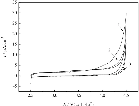
2.5 3.0 3.5 4.0 4.5
-5 0 5 10 15 20 25 30 35 2 3 i / μ cm 2
E / V(vs Li/Li+)
1
[image:4.596.153.420.497.701.2]
[image:5.596.104.497.69.263.2]
(a) (b)
[image:5.596.162.426.442.637.2]Figure 3. TEM images of the pristine (a) and 2 % Sb2O3-coated LiMn2O4 (b)
Fig.2 shows the CV curves of the pure Sb2O3 electrode. From Fig. 2, the oxidative peak occur
after 4.0V and the value of the oxidative current is about 10-6A. Compared to the value of the oxidative current of LiMn2O4 (10-3A), the current is so small that we think Sb2O3 is inactive. Fig. 3 exhibits the
TEM images of pristine (a) and 2 % Sb2O3-coated LiMn2O4 (b). As expected, it is clearly observed that
a layer with the thickness of 8 nm was coated on the surface of LiMn2O4.
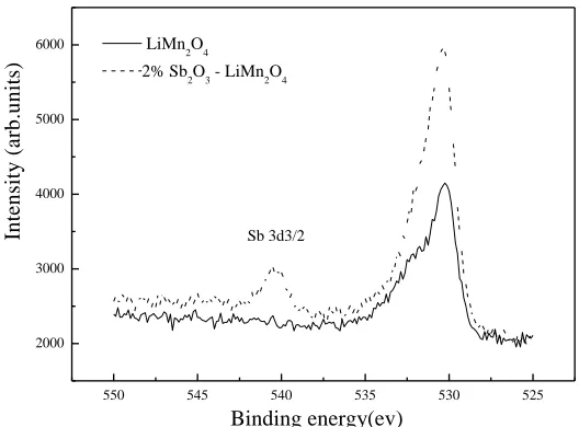
550 545 540 535 530 525
2000 3000 4000 5000 6000
Sb 3d3/2
LiMn2O4
2% Sb2O3 - LiMn2O4
In
te
n
si
ty
(
a
rb
.u
n
it
s)
Binding energy(ev)
Figure 4. The Sb3d3/2 XPS spectra of the surface of the pristine LiMn2O4 (solid line) and 2% Sb2O3
-coated LiMn2O4 (dash line)
XPS is an effective method to provide the elemental oxidation states analysis of the surface film[20,21]. Thus, the surface of the 2 % Sb2O3-coated LiMn2O4 electrodes was detected by XPS. Fig.
of 2 % coated LiMn2O4, an obvious peak occurs at 540 eV which can be contributed to the Sb3d3/2 of
Sb2O3[22,23], while there is no peak at 540 eV in the pristine LiMn2O4. It can be speculated from the
XPS spectra that the Sb2O3 exist in the surface of Sb2O3-coated LiMn2O4. Associated with the results
of XRD, we suppose that two kinds of antimony compound, Sb2O3 and LiSbxMn2-xO4 all exist on the
surface of modified LiMn2O4.
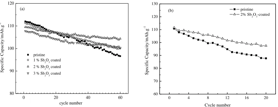
Fig. 5 shows the charge-discharge curves of the pristine and Sb2O3-coated LiMn2O4 performed
during cycles at room temperature and high temperature. From Fig. 5a, the initial discharge capacity of the coated materials is lower than that of the pristine LiMn2O4 and decrease with the increase of Sb2O3,
which is similar to other oxide-coated cathodes [24,25]. The initial discharge capacities of pristine LiMn2O4, 1 %, 2 % and 3 % Sb2O3 coated LiMn2O4 are 116.4 mAh g-1, 115.7 mAh g-1, 115.1 mAh g-1
and 113.5 mAh g-1, respectively. On the other hand, the capacity of pristine material declines to 96.6 mAh g-1 after 60 cycles, which shows the capacity loss of 13.7 %. By contrast, the coated LiMn2O4
exhibits small capacity loss, especially 2% coated material (only 6.5%). The cycle stability is significantly improved by Sb2O3 coating. The decrease of the initial discharge capacity of coated
materials is mainly caused by the inactive Sb2O3.
The cycling performance of pristine and 2 % Sb2O3 coated-LiMn2O4 at 55°C between 3.0V and
4.3V are illustrated in Fig.5b. As can be seen, the Sb2O3 coating can significantly reduce the capacity
fading of LiMn2O4 at elevated temperature. The uncoated-LiMn2O4 delivers a discharge capacity of
110.8 mAh g-1 at the first cycle and remains only 87.7 mAh g-1 after 20 cycles with the capacity loss of 20%. While under the same conditions, 12.6 % capacity loss is found for 2% Sb2O3 coated LiMn2O4.
These results obviously suggest that the surface modification of LiMn2O4 spinel with Sb2O3 is
effective to reduce capacity fading of LiMn2O4 at elevated temperature.
0 20 40 60
80 90 100 110 120 pristine
1 % Sb2O3 coated
2 % Sb2O3 coated
3 % Sb2O3 coated
S p e c if ic C a p a c it y /m A h .g -1 cycle number (a)
0 4 8 12 16 20
60 70 80 90 100 110 120 130 S p ec if ic C ap ac it y /m A h .g -1 Cycle number pristine 2% Sb2O3-coated
(b)
Figure 5. Discharge capacities of pristine and Sb2O3-coated LiMn2O4 cathodes at the range of
3.0-4.3V with a constant current density of 0.2C at 25°C (a) and 55°C (b)
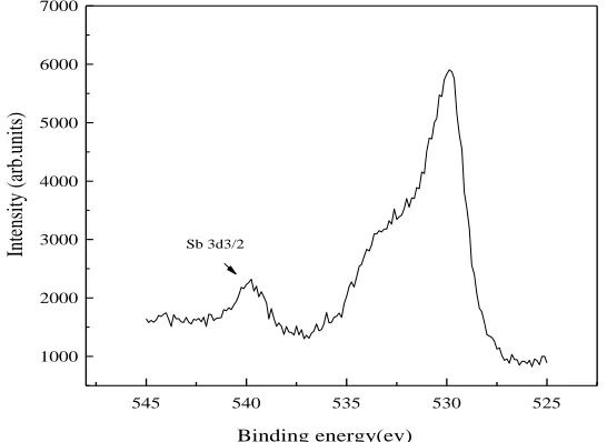
In order to understand the mechanism of improved cycling performance of Sb2O3
coated-LiMn2O4, we investigated the stability of Sb2O3 during cycle process. Fig.6 shows the Sb3d3/2 XPS
[image:6.596.71.525.475.650.2]
ev[22,23], which is in accordance with fresh sample. These results imply that the Sb2O3 on the surface
of the LiMn2O4 particle has good stability. Combined with the TEM, we supposed that the coating
layer and the surface solid solution layer can reduce the contact area of LiMn2O4 electrode/electrolyte
interface and partly suppress the dissolution of the Mn ions from the spinel into the electrolyte.
545 540 535 530 525
1000 2000 3000 4000 5000 6000 7000
In
te
ns
it
y
(a
rb
.u
ni
ts
)
Binding energy(ev)
[image:7.596.161.434.175.374.2]Sb 3d3/2
Figure 6. The Sb3d3/2 XPS spectra of the surface of the 2% Sb2O3-coated LiMn2O4 after 30 cycles
The electrode/electrolyte interface is another important factor on the electrochemical performance of LiMn2O4 except for the structure stability of the cathode materials. EIS was measured
to investigate the kinetics of Li+ insertion/desertion into the pristine and Sb2O3 coated LiMn2O4. Fig. 7
shows the Nyquist plots of bare and Sb2O3-modified LiMn2O4 after different cycles. Both spectra have
the high frequency semicircles, the middle frequency semicircles and the low frequency tails. The impedance spectra were fitted with the equivalent circuit model (insert in Fig. 7a.). As other models[18,26-27], this model also consist of Li+ migration through the surface film, charge-transfer through the electrode-electrolyte interface and the solid-state diffusion of Li+ in the material. In this circuit, Rs denotes the ohmic resistance, Rf and CPE1 are the surface film resistance and film
capacitance, Rct and CPEdl are charge transfer resistance and double layer capacitance at the electrolyte-electrode interface, and W represents the diffusion impedance, respectively. From Fig. 7a, the LiMn2O4 cathode and Sb2O3-modified LiMn2O4 cathode have similar EIS after the second cycle,
which indicates that two kinds of cathode have analogous kinetic character. However, there is the obvious difference in Fig. 7b. The parameters of the equivalent circuit obtained from computer simulations are shown in Table 1. It can be seen that the Rct of pristine LiMn2O4 increases from 13.0Ω
to 36.1Ωand the coated sample only increases from 15.0Ω to 29.2Ω. Obviously, the Sb2O3 coating can
0 10 20 30 40 50 60
0 10 20 30 40 50 60
LiMn2O4
1 % Sb2O3 coated-LiMn2O4
-Z
"/
o
h
m
Z'/ohm
(a)
0 20 40 60 80
0 20 40 60 80
-Z
"/
oh
m
Z'/ohm
LiMn
2O4
1 % Sb
2O3 coated-LiMn2O4
[image:8.596.65.530.74.252.2](b)
[image:8.596.42.550.347.439.2]Figure 7. Electrochemical impedance spectroscopy of the electrodes after 2 cycle (a) and 30 cycles(b)
Table 1. Simulated impedance parameters using the equivalent circuit
Pristine 1% Sb2O3
2th 30th 2th 30th
Rs (Ω) 5.07 4.95 4.67 4.71
Rf (Ω) 11.5 13.0 10.1 11.3
Rct (Ω) 13.0 36.1 15.0 19.0
Fig. 8 shows the TG-DSC profiles of LiMn2O4 and 2%Sb2O3 coated LiMn2O4 in charged state
with fresh electrolyte. TG profiles show that the weight of each crucible was constant, indicating that no leakage was occurred during experiments. DSC curve of pristine LiMn2O4 obviously shows three
exothermic reactions from 210◦C to 330◦C. 2%Sb2O3 coated LiMn2O4 exhibits a small hump around
175℃ and then slowly generates heat from 210◦C. The estimated total heat generation of pristine LiMn2O4 is 470 w·g-1 while the 2%Sb2O3 coated LiMn2O4 shows a lower heat of 240 w·g-1, which is
49% less than that of pristine LiMn2O4. It is expected that the coating not only reduces the direct
contact between electrolyte and active materials, but also stabilizes the surface structure of active material, which thus inhibits the oxygen from active materials and then finally increases the thermal stability of the active materials. On the other hand, Sb2O3 itself is a usual inorganic flame retardants,
0 50 100 150 200 250 300 350 400 450 0.0
0.5 1.0 1.5 2.0 2.5
20 40 60 80 100
M
a
ss
/
%
LiMn2O4
2% Sb2O3-LiMn2O4
P
o
w
e
r
/
w
g
-1
Temperature / 0C
[image:9.596.164.431.73.259.2]
Figure 8. TG-DSC profiles of charged LiMn2O4 and Sb2O3 coated LiMn2O4 with electrolyte
4. CONCLUSION
Sb2O3 was coated on surface of LiMn2O4 by chemical precipitation method. The initial
discharge capacity was decreased with the increase of Sb2O3 content. Compared to the other proportion
samples, 2% Sb2O3-coated LiMn2O4 sample exhibited slightly decrease of original specific capacity
but maintained excellent capacity retention. The Sb2O3 coating reduced the contact area of LiMn2O4
electrode/electrolyte interface and suppressed the augment of charge transfer resistance during cycling, which guaranteed the enhanced electrochemical performance of Sb2O3-coated LiMn2O4. At the same
time, the thermal stability of LiMn2O4 was improved by Sb2O3 coating.
ACKNOWLEDGMENTS
We express our appreciation for the support from the National Natural Science Foundation of China (No. 51202047), the Fundamental Research Funds for the Central Universities (No. HIT. NSRIF. 2011022) and the Heilongjiang Postdoctoral Fund (LBH-Z11141).
References
1. R.J. Cummow, A.D. Kock and M.M. Thackeray. Solid State Ionics. 69 (1994) 59.
2. A.D. Robertson, S.H. Lu, W.F. Acerill and J.R. Howard. J. Electrochem. Soc. 144 (1997) 3500. 3. G.G. Amatucci, N.Pereira, T. Zheng, I. Plits and J.M. Tarascon. J. Power Sources. 81- 82 (1999)
39.
4. Y. Xia and M. Yoshio. J. Power Sources. 66(1-2) (1997) 129.
5. M.M Wohlfahrt, C.Vogler and J. Garche. J. Power Sources. 127 (2004) 58. 6. T. Inoune and M. Sano. J. Electrochem. Soc. 145 (1998) 3704.
7. L.J. Fu, H. Liu, C. Li, Y.P. Wu, E. Rahm, R. Holze and H.Q. Wu. Solid State Sciences. 8 (2006) 113.
10.J. S. Gnanaraj, V. G. Pol, A. Geranken and D. Aurbach. Electrochem. Comm., 5 (2003) 940. 11.W. K. Kim, D. W. Han, W. H. Ryu, S. J. Lim and H.S. Kwon. Electrochim. Acta. 71 (2012) 17. 12.D.Q. Liu, X. Q. Liu and Z. Z. He. J. Alloys and Comp. 436 (2007) 387.
13.J. Cho, T. J. Kim, Y. J. Kim and B. Park. Chem. Comm., 12 (2001) 1074.
14.Y.M. Lin, H.C.Wu, Y.C.Yen, Z. Z. Guo, M. H. Yang, H.M,Chen, H. Sheu and N. Wu. J. Electrochem. Soc., 152 (2005) A1526.
15.H.Ha, N. Yun and K.Kim. Electrochim. Acta. 52 (2007) 3236.
16.L.H.Yu, X.P.Qiu, J.Y.Xi, W.T.Zhu and L.Q.Chen. Electrochim. Acta. 51 (2006) 6406. 17.J.P.Yu, X.H.Hu, H.Zhan and Y.H.Zhou. J. Power Sources. 189 (2009) 697.
18.R. Guo, P.F.Shi, X. Q. Cheng and L. Sun. Electrochim. Acta. 54 (2009) 5796. 19.J.Cho, Y. J. Kim and B. Park. Chem. Mater. 12 (2000) 3788.
20.A. Schechter and D. Aurbach. Langmuir. 15 (1999) 3334. 21.R. Yazami. Electrochimica Acta. 45 (1999) 87.
22.H.D. Zhang, K.Q. Sun, Z. C. Feng, P. L. Ying and C. Li. Appl. Catal., A. 305 (2006) 110. 23.X.Y.Chen, X.Wang, C.H.An, J.W.Liu and Y.T.Qian. Mater. Res. Bull., 40(2005) 469. 24.D. Arumugam and G. P. Kalaignan, Electrochim. Acta. 55 (2010) 8709.
25.L. Wang, J.S.Zhao, S.H.Guo, X.M. He, C.Y.Jiang and C.R. Wan, Int. J. Electrochem. SC.5(2010)1113.
26.M.D. Levi, G. Salitra, B. Markovsky, H. Teller, D. Aurbach, U. Heider and L. Heider. J. Electrochem. Soc., 146 (1999) 1279.