Article
Performance Study on A Window Type Air
Conditioner Condenser Using Alternative Refrigerant
R407C
Abdul Hadi N. Khalifa
1,a,*
, Johain J. Faraj
1,b, and Ali K. Shaker
2,c1Engineering Technical College Baghdad, Middle
Technical
University-Iraq.
2Engineering Technical College Basra, Southern Tech. University-Iraq.
E-mail: a[email protected](Corresponding author)
,
b[email protected],
ce
[email protected]Abstract
.
In this work, a performance study was achieved on air cooled condenser of an air-conditioning unit. An experimental investigation was carried out on two condenser designs aided by a controlled environmental zone, which was designed and constructed for the current study. The effect of ambient air temperature on the condenser performance was studied by varying the controlled zone air temperature from 30 to 50oC. The firstdesign is a four circuits 5/16" (8 mm) tube diameter condenser and the second is an eight circuits design with the same diameter. The experimental results showed that, an increase in the ambient air temperature has a negative effect on COP due to the decrease in the overall heat rejected, yet has a positive effect on refrigerant side pressure drop.
Keywords: Air cooled condenser, air conditioning, finned-tube condenser, refrigeration system.
ENGINEERING JOURNAL Volume 21 Issue 1
1.
Introduction
The HCFC known as R-22 has been the refrigerant of choice for residential heat pump and air-conditioning systems for more than four decades. Unfortunately from the environmental prospective, the release of R-22 resulting from system leaks contributed adversely to ozone depletion. In addition, the manufacture of R-22 results in a by-product that contributes significantly to global warming. As the production of R-22 is phased out over the coming years as part of the agreement to end production of HCFCs, manufacturers of residential air conditioning systems commenced offering equipment that uses ozone-friendly refrigerants. Two refrigerant mixtures have been identified (R410 and R407), extensively studied, and determined to be viable alternatives to HCFC- 22. R-407C is a blend of HFC-32, HFC-125 and HFC-134a (23/25/52 weight %) and was specifically designed to closely match HCFC-22 performance with minimal design changes. But when retrofitting an old air conditioning unit with R407C alternative refrigerant, the system suffers from about 5% reduction in efficiency [1]. The direct method to improve the efficiency of VCR is to enhance the performance of the air-cooled condensers. There are two types of condenser circuits namely U-type and Z-type, in U-type the refrigerant flows in U-path without inclined bends while in Z-type the refrigerant flows path is through many Z-paths which have many inclined bends with a pressure drop larger than U-path [2]. The author of [3] developed an optimization methodology and software for air cold condenser using R22 as a working fluid. An EES program was used as a software tool, and the seasonal COP was taken as the figure of merit. The optimization was performed under two constraints, first at fixed cost and varying frontal area and second by fixed frontal area with varying cost. The authors of [4] provided guidelines for design and optimization of air cooled condenser and investigated various two phase flow heat transfer and pressure drop calculation methods for R410A refrigerant. The authors of [2] studied numerically the finned tube air cooled condenser performance to find the optimal circuit path. They performed the optimization by using two different configurations of condenser circuits, namely Z and U paths, with different condenser capacity and two refrigerants R22 and R407C. The authors of [5] and [6] have optimized the geometric design and operational parameters of cross flow finned tube air cooled condenser of R410A residential air conditioner. The parameters included were coil cost, frontal area, and aspect ratio constraint. The authors of [7] developed a system model and optimization methodology to compare the COP of an R410A residential air conditioner using optimized plain fin condenser design, with fixed frontal area and aspect ratio. The simplex search method was used to find a good optimum design. The authors of [8] optimized the air cooled condenser for window type air conditioner with a uniform air flow and split unit air conditioner with non-uniform air flow. They optimized the condenser by changing circuitry arrangements from one circuit to seven circuits and kept all other parameters constant. The authors of [9] studied the effect of the inclination angle and aspect ratio (transverse pitch of parallel tubes divided by width of flat tube cross section) on the performance of air cooled condenser. They investigated the methods to improve the convective heat transfer in air condition system. The authors of [10] compared the cooling effect of shift refrigerant R-12 with that for R404A in a cold store. The work of authors [11] include a thermodynamic analysis, experimental testing and determination of the environmental impact of the refrigerant selection. Two alternatives to R22 were studied: the first on was HFC-407C and the second was HFO-R444B. The authors of [12] have built a mathematical rating model for an air cooled louvered finned tube condenser. The steady state experimental data of a window type AC of 2 ton of refrigeration capacity was used to build a tube by tube model to investigate the evaporator performance. The refrigerants selected for this object were R22 and the zeotropic blends R407C and R407A refrigerants.
In the current work an attempt was made to enhance the performance of the air cooled condenser retrofitted with R407 since this refrigerant resulted in some performance problems to air conditioning systems working in Iraq climate. Two condensers with 4 and 8 circuits' designs were tested. The designs then have been subjected to a range of ambient temperatures to measure the pressure drop in different sections of the condenser, as well as the rate of heat transfer.
2.
Experimental Setup
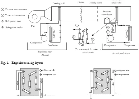
distribution along the test zone. The comb was placed at a distance of 19 cm from the tested condenser. An evaporator coil of window type air conditioner of 2 tons cooling capacity, with specifications shown in Table 1, was inserted inside the duct, while the other components of unit (compressor, condenser coil and fan) were located outside test zone. To achieve the required supply air temperature (as ambient air temperature for summer seasonal in Iraq), eight electrical heaters of 1000 Watt capacity each, were inserted inside the air duct, as shown in Fig. 1 .The voltage drop across heater was regulated by a solid state voltage regulator with heat sink. Since U shape bends has less pressure drop than Z shape [2], Z shape circuits were excluded. Two condenser circuit types were tested. The first circuit is a four tube loops with U shape bends as shown in Fig. 2a. The second circuit is an eight tube loops with U shape bends as shown in Fig. 2b. In both condensers, the geometry of condenser tubes and number of fins per tube have not been changed.
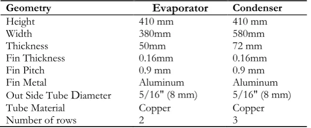
Table 1. Evaporator and condenser specifications.
Geometry
Evaporator
CondenserHeight 410 mm 410 mm
Width 380mm 580mm
Thickness 50mm 72 mm
Fin Thickness 0.16mm 0.16mm
Fin Pitch 0.9 mm 0.9 mm
Fin Metal Aluminum Aluminum
Out Side Tube
D
iameter 5/16" (8 mm) 5/16" (8 mm) Tube Material Copper CopperNumber of rows 2 3
A wavy fin condenser was selected and modified to comply with the new circuit design by rearranging the end U bends. An L-Shaped tube of 0.5" (12.5 mm) diameter drilled along its length with four 5/16 " ( 8mm) holes was used as an end header. A reciprocating compressor from Bristol Int. Company of 5.27 kW capacity is used with all mechanical specifications were measured experimentally. The original mineral oil was bled and replaced by polyester oil to conform to R407C [13], [14] found that for a given capillary tube length and diameter the mass flow rate of R407C is less than that for R22 under the same conditions. Thus, to maintain the same mass flow rate for the same tube diameter, the length of capillary tube used with R407C should be about 90% of that used with R22.
The heat rejected from condenser can be found as follow:
̇ (1)
where is the rate of heat rejected from condenser (kW), ̇ is the mass flow rate of refrigerant
(kg/s), : are enthalpies at inlet and outlet from condenser (kJ/kg) The capacity of the AC unit is calculated as follows:
̇ (2)
where is rate of heat rejected from evaporator (kW), and are the enthalpies at inlet and
outlet from evaporator (kJ/kg).
Compressor power consumption can calculated from Eq. (3) as follows:
̇ (3)
where is compressor power consumption (kW), , and are the enthalpies at inlet and
outlet from compressor (kJ/kg).
Finally the Coefficient Of Performance (COP) of the vapour compression cycle is found from the following equation:
(4)
3.
Measurements and Instrumentation
[image:3.595.142.457.240.370.2]used to measure the temperatures. The thermometer was connected to selector switch of 30 points of measurements, each point was connected to terminal thermocouple of T-type. Three thermocouples were attached to each circuit of the condenser circuits, at the inlet, outlet and at the middle of the circuit, as shown in Fig. 1. A digital anemometer of type DA40 that gives the average velocity of two time reading (Max. 16 sec and Min. 2sec ) was used to measure the supply air velocity. The error analysis of the experimental work is shown in Appendix A, Table A-1.
T T P T P T Compressor Condenser
Cooling coil Heater Honey comb
Condenser under test
Thermocouple location on each circuit
Evaporator Compressor
Fan
Supplementary
AC unit Ac unit under test Pressure
transducer
T P Pressure measurement
Temp. measurement Refrigerant inlet Refrigerant outlet T
Fig. 1. Experimental rig layout.
A A Refrigerant inlet Refrigerant exit A A Refrigerant inlet Refrigerant exit
Fig. 2a. Section in four Circuits condenser showing
one circuit Fig. 2b. Section in eight circuit' condenser showing two circuits
4.
Results and Discussions
The condensation process evolved in three regions: gas region (characterized by superheated vapor), wet region (characterized by two phase flow) and liquid region (characterized by sub-cooled liquid). An increase in ambient temperature results eventually in an increase in the saturation temperature and saturation pressure of refrigerant. This leads to a decrease in the area available for the two phase region in the condenser as shown in Fig. 3. Figures 4 to 6 delineate the effect of ambient temperature on the pressure drop in two phase, gas and liquid regions, respectively for both four and eight circuits' condenser. The two phase region has the biggest contribution to the total pressure drop in the condenser, due to momentum change. For example, the wet region pressure drop contributed by about 80% of the entire drop at 30oC
[image:4.595.66.512.173.490.2]Ambient temp. equals to 30 oC Ambient temp. equals to 40 oC Ambient temp. equals to 50 oC
Fig. 3. Pressure-enthalpy diagram of R407C shows different refrigeration cycle operate at different ambient temperature.
[image:5.595.139.459.83.245.2]The condensation heat transfer coefficient varies for gas, two phase and sub cooled regions. In two phase region where the change in phase occurs, the process is characterized by large heat transfer coefficient values. Therefore heat transfer in the two phase region represents the largest ration of the total condensation heat transfer. The effect of ambient temperature is depicted in Fig. 7 for the two phase region. This phenomenon leads to a decrease in the amount of heat rejection from two phase region, as shown in Fig. 8.
Fig. 4. Pressure drop in two phase region vs. ambient temperature for both four and eight circuits' condenser.
Fig. 5. Pressure drop in gas region vs. ambient temperature for both four and eight circuits'
[image:5.595.332.499.374.541.2] [image:5.595.95.265.375.540.2]Fig. 6. Pressure drop in liquid region vs. ambient temperature for both four and eight circuits condenser.
[image:6.595.98.265.79.246.2]Fig. 7. Heat transfer coefficient of two phase region vs. ambient temperature for four and eight circuits condenser.
Fig. 8. Heat rejected from two phase region versus ambient temperature for four and eight circuits' condensers.
Fig. 9. Heat transfer coefficient of liquid and gas regions versus ambient temperature for four circuits' condenser.
Figures 10 and 11 reveal the effect of ambient temperature on the heat rejected from each individual circuit of the four circuits' condenser for both liquid and gas regions, respectively. The rejected heat rises significantly when the ambient temperature is above 40oC, while it rises gradually for gas region. The
[image:6.595.323.498.285.456.2] [image:6.595.88.268.285.455.2]Fig. 10. Heat rejected from liquid refrigerant in each circuit of the four circuits condenser versus ambient temperature.
Fig 11. Heat rejected from gas refrigerant in each circuit consist the four circuits condenser versus ambient temperature.
Fig. 12. Overall heat rejected from refrigerant in each circuit consist the four circuits condenser versus ambient temperature.
Fig. 13. Effect of ambient temperature on the effectiveness of the four and eight circuits' condenser.
[image:7.595.93.267.78.244.2] [image:7.595.329.501.287.454.2] [image:7.595.94.263.287.454.2] [image:7.595.216.383.506.675.2]5.
Conclusions
1. As the ambient temperature increases the refrigerant side pressure drop decreases, due to decrease in the length of two phase region which has the largest ratio of the total condenser pressure drop. 2. Condenser effectiveness was insensitive to ambient air temperature changes. This resulted in an
increase in compressor mass flow rate of refrigerant to maintain the required condenser capacity. On the other hand, it has a negative effect on COP due to increase in the associated compressor work.
3.
The optimal condenser design (5/16" (8 mm) tube diameter with four circuits) gave 1.2 % increase in COP as compared to the base case of one tube when retrofitted with R407C.Nomenclature:
COP :
h:
̇
:
Q:
W:
Coefficient of performance
E
nthalpy(kJ/kg)
Mass flow rate
(kg/s)
Rate of heat transfer
(kW)
Power consumption
(kW)
Subscripts:
comp.:
cond.:
e:
evap.:
i:
r:
Compressor
Condenser
Exit
Evaporator
Inlet
Refrigerant
References
[1] AIRAH. Refrigeration selection Guide, 7th ed. Australian Institute of Refrigeration, Air conditioning and Heating Inc. Level 7 Melbourne, 2003.
[2] J. H, S. Lee, W. Bae, K. H. Bang, and M. H. Kim. “Experimental and numerical research on condenser performance for R-22 and R-407C refrigerants,” International Journal of Refrigeration, vol. 25, no. 3, 2002.
[3] E. M. Sadler, “Design analysis of a finned-tube condenser for a residential air-conditioner using R-22,” Ph
.
D.
diss., Georgia Institute of Technology, 2000.[4] M. F. Wright, “Plate-Fin-And-Tube condenser performance and design for a refrigerant R-410 A air-conditioner,” M.S. thesis, School of Mechanical Engineering, Georgia Institute of Technology, 2002. [5] S. W. Stewart, K. A. Aspelund, M. F. Wright, E. M. Sadler, and S. V. Shelton. “Residential air
conditioner finned-tube condenser heat exchanger optimization,” in Southeastern Region XI Technical Conference, 2002.
[6] K. A. Aspelund, “Optimization of plate-fin-and-tube condenser performance and design for refrigerant R-410A air-conditioner,” Ph.D
.
diss., Georgia Institute of Technology, 2001.[7] S. W. Stewart and S. V. Shelton, “Finned-tube condenser design optimization using thermos-economic isolation,” Applied Thermal Engineering, vol. 30, no. 14, pp. 2096-2102, 2010.
[8] P. A. Domanski and D. Yashar, “Optimization of finned-tube condensers using an intelligent system,” International Journal of Refrigeration, vol. 30, no. 3, pp. 482-488, 2007.
[9] M. M. Awad, H. M. Mostafa, G. I. Sultan, A. Elbooz, and A. M. K. El-Ghonemy, “Performance enhancement of air-cooled condensers,” Acta Polytechnica Hungarica, vol. 4, no. 2, pp. 125-142, 2007. [10] S. Akdemir and S. Arin, “Determination of cooling effect of R12 and R404A,” J. Biol. Sci., vol. 3, pp.
1114-1125, 2003.
[12] A. H. Tarrad and A. K. Al-Nadawi, “A rating model for air cooled condensers using pure and blend refrigerants,” American Journal of Science and Technology, vol. 3, no. 1, pp. 1-11, 2016.
[13] P. M. Banfi, “Development of lubricants for industrial refrigeration,” Castrol International – Development of lubricants for industrial refrigeration, 2003.
[14] C. N. Kim and Y. M. Park, “Investigation on the selection of capillary tube for the alternative refrigerant R-407C,” International Journal of Air-Conditioning and Refrigeration, vol. 8, no. 1, pp. 40-49, 2002.
Appendix A:
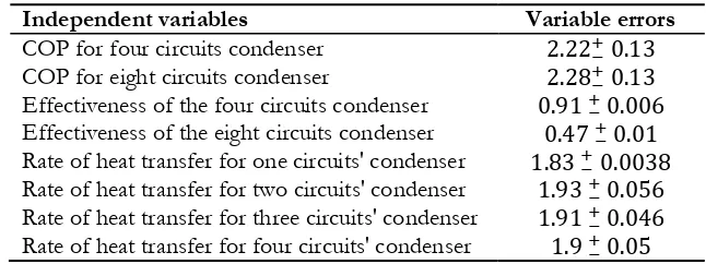
[image:9.595.134.457.252.373.2]Error Analysis:
Table A-1. Experimental accuracy.
Independent variables Variable errors
COP for four circuits condenser
COP for eight circuits condenser
Effectiveness of the four circuits condenser
Effectiveness of the eight circuits condenser
Rate of heat transfer for one circuits' condenser
Rate of heat transfer for two circuits' condenser
Rate of heat transfer for three circuits' condenser