vibro-impact systems
.
White Rose Research Online URL for this paper:
http://eprints.whiterose.ac.uk/79689/
Version: Accepted Version
Article:
Wagg, D.J. (2006) Multiple nonsmooth events in multi-degree-of-freedom vibro-impact
systems. Nonlinear Dynamics, 43 (1-2). 137-148 . ISSN 0924-090X
https://doi.org/10.1007/s11071-006-0757-7
Reuse
Unless indicated otherwise, fulltext items are protected by copyright with all rights reserved. The copyright exception in section 29 of the Copyright, Designs and Patents Act 1988 allows the making of a single copy solely for the purpose of non-commercial research or private study within the limits of fair dealing. The publisher or other rights-holder may allow further reproduction and re-use of this version - refer to the White Rose Research Online record for this item. Where records identify the publisher as the copyright holder, users can verify any specific terms of use on the publisher’s website.
Takedown
If you consider content in White Rose Research Online to be in breach of UK law, please notify us by
Multiple nonsmooth events in multi-degree-of-freedom
vibro-impact systems
David J. Wagg
Department of Mechanical Engineering, University of Bristol, University Walk, Bristol BS8 1TR, U.K
October 19, 2004
Abstract.
The behaviour of a multi-degree-of-freedom vibro-impact system is studied using a two degree-of-freedom impact oscillator as a motivating example. A multi-modal model is used to simulate the behaviour of the system, and examine the complex dynamics which occurs when both degrees of freedom are subjected to a motion limiting constraint. In particular the chattering and sticking behaviour which occurs for low forcing frequencies is discussed. In this region a variety of nonsmooth events can occur, including newly studied phenomena such as sliding bifurcations. In this paper the multiple nonsmooth events which can occur in the two degree-of-freedom system are categorised, and demonstrated using numerical simulations.
Keywords: Vibro-impact, multiple constraint, chatter, sticking, sliding
1. Introduction
This paper deals with the dynamics of multi-degree-of-freedom impact oscillators subject to multiple motion limiting constraints. These sys-tems consist of a set of coupled masses, where the motion of each of the masses is restricted by a series of motion limiting constraints. This paper will consider a two degree-of-freedom system with constraints placed a different distances from each mass [1]. Several authors have considered two constraints placed an equal distance either side of an oscillating mass, e.g. [2–4].
Two degree-of-freedom impact oscillator systems have been studied in relation to a range of applications [5–7]. More general multi-degree-of-freedom impact systems have also been considered by several other authors [8–11]. Of particular interest have been periodic impacting orbits which occur in multi-degree-of-freedom impact systems. Systems with a single impact stop have been studied [12, 13], and the method for finding period(1, n) solutions developed for single degree-of-freedom impact oscillators by [14] has been extended to multi-degree-of-freedom impact oscillators [12]. Studies into bifurcations in this type of system have also been carried out, for example [15].
degree-of-freedom systems [18]. The behaviour of periodic sticking motions in both single and multi-degree-of-freedom systems has also been studied [19]. The sticking phenomena observed here is analogous to the sliding in other systems [20], as discussed in [21]. In this paper we consider the same two degree-of-freedom example studied in [1], but examine the multi-dimensional nonsmooth events which can occur in the chatter and sticking region.
2. Mathematical Model
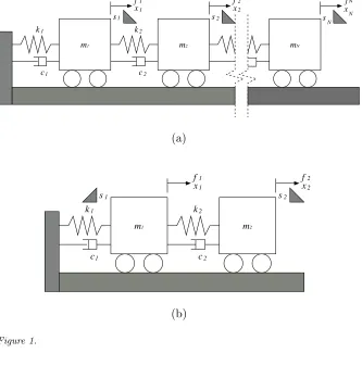
A schematic model of the generalized N degree-of-freedom coupled linear oscillator system with N lumped masses is shown schematically in Figure 1 (a). In general, the equations of motion for the coupled masses can be expressed as
mix¨i+ci( ˙xi−x˙i−1)+ci+1( ˙xi−x˙i+1)+ki(xi−xi−1)+ki+1(xi−xi+1) =fi(t),
(1) for i= 1,2. . . , N−1 and
mNx¨N +cN( ˙xN −x˙N−1) +kN(xN −xN−1) =fN(t) (2)
for i = N, where xi and fi(t) represent the displacement and forcing
of mass mi, and an overdot is used to represent differentiation with
respect to time t. These expressions govern the motion while all the displacementsxi are less than some fixed set of valuessi corresponding
to the position of the motion constraints.
The equations of motion for the coupled masses can be expressed in matrix form as
[M]¨x+ [C] ˙x+ [K]x=f(t), (xi−si)≶0 ∀si≷0 (3)
where [M],[C],[K] are the mass, damping and stiffness matrices re-spectively, x={x1, x2. . . , xN}T is the displacement vector andf(t) =
{f1, f2. . . , fN}T the external forcing vector. The coupling between masses
occurs via the matrices [C] and [K], which are nondiagonal. The mass matrix [M] is a diagonal matrix. Equation (3) has the dual condition for free flight that (xi−si)<0 for si>0 and (xi−si)>0 forsi<0.
It is assumed that the damping matrix [C] is linearly proportional to the stiffness matrix [K], such that Equation (3) can be decoupled in the standard way [22]. In this work the case where mj =m,cj =c, kj = k for j = 1,2, . . . , N, is considered. Then Equation (3) can be
written in the form
[I]¨x+ c
m[E] ˙x+ k
m[E]x=
1
where [E] is the N ×N coupling matrix
[E] =
2 −1 0 . . . 0
−1 2 −1 . . . 0 ..
. . . .. . . . ... 0 . . . −1 2 −1 0 . . . 0 −1 1
, (5)
and [I] is the identity matrix.
The natural frequencies are given byωnj =
q
λjk/mforj= 1,2, . . . , N
whereλj are the eigenvalues of matrix [E], and the corresponding
nor-malized eigenvectors ξj can be used to construct a orthogonal modal
matrix [Ψ] = [{ξ1},{ξ2}, . . . ,{ξN}]. Equation (4) can then be
trans-formed into a modal form by defining modal coordinates x = [Ψ]q
where q={q1, q2, . . . qN}T, such that
[I]¨q+ c
m[Λ] ˙q+ k
m[Λ]q=
1
m[Ψ]
Tf(t) (6)
where [Λ] = [Ψ]T[E][Ψ] is the diagonal matrix of the eigenvalues, λ j, j = 1,2, ...N.
In this modal formulation the vector ψi ={Ψi1,Ψi2, . . . ,ΨiN}T, is
defined such that an impact occurs when ψT
i q=xi. Hence equation 6
is valid only for (ψT
i q−si) ≶ 0 ∀si ≷ 0, which is equivalent to the
condition that (xi−si)≶0 ∀si≷0 for theith impacting mass.
The system is considered to be subject to harmonic forcing of the form f(t) =Acos(Ωt), whereA={A1, A2, . . . , AN}T, then equation 6
can be simplified such that for each mode
¨
qj+ 2ζjωnjq˙j+ωnj2 q =
ˆ
fj
mcos(Ωt), j= 1,2, . . . , N (7)
where ˆf = [Ψ]TA, ˆf = {fˆ
1,fˆ2, . . . ,fˆN}T and ζj = (c/2)
q
λj/km is
the modal damping coefficient. Equation (7) has the well known exact solution for under-damped oscillations 0 < ζj < 1 [22] such that for
each mode an exact solution can be obtained, and from this the total displacements for x[1].
2.1. Modelling impacts for systems with multiple constraints
An impact occurs for the ith mass whenxi =si, while forj6=i:(xj − sj)≶0 ∀sj ≷0. To model the impact an instantaneous coefficient of
restitution rule is used [23]
˙
where,t−is the time just before impact,t+is the time just after impact andr is the coefficient of restitution with a value in the ranger ∈[0,1]. For systems with multiple constraints the matrix form the coefficient of restitution rule is
˙
x(t+) = [R] ˙x(t−) (xi−si) = 0 (9)
where [R] is theN×N diagonal coefficient of restitution matrix. For a system withN impacting masses [R] will have a different form depend-ing on whether sdepend-ingle, multiple or all the masses make contact durdepend-ing the impact process [1].
In modal form the coefficient of restitution rule, Equation 9, for a single impact becomes
[Ψ] ˙q(τ+) = [R][Ψ] ˙q(τ−), (ψ
T
i q−si) = 0. (10)
This leads to the relation for the modal velocities after impact
˙
q(τ+) = [ ˆR] ˙q(τ−), (ψ
T
i q−si) = 0, (11)
where [ ˆR] = [Ψ]−1[R][Ψ] is the set of matrices which represents a linear
transform of modal velocities just before impact to modal velocities just after impact for all the possible impact cases.
2.2. Sticking motion
Sticking motions occur when one or more of the masses is held motion-less against the stop for a finite period of time. Sticking motions can occur in multi-degree-of-freedom impact oscillators after a complete chatter sequence has occurred [16, 18]. A chatter sequence becomes complete when the time between two successive impacts, δt becomes small, while at the same time the forces on the mass hold it against the impact stop. So, in order to reach a sticking solution for a single mass (the pth say) chatter must be complete, i.e δt≈0 and the force acting on the sticking mass must hold it against the constraint, which is equivalent to the condition Fpsp > 0. This is similar to conditions
for a relay system referred to as the reaching conditions [20]. There is one possible exception to these conditions, that is if a mass comes into contact with the stop with zero velocity and acceleration and simultaneously Fpsp > 0 becomes true. This non-generic case is an
example of a grazing-sliding bifurcation discussed in section 3.3. To find the force Fp, we substitute xp =sp and ˙xp= 0 into the pth
line of Equation (4). So for 1≤p < N from Equation (1) with allm, c
and k values equal
and for p=N from Equation (2),
Fp =cx˙p−1+kxp−1+fp(t)−ksp. (13)
The end of sticking is defined as whenFp changes sign.
As a result, Equations (12) and (13) set equal to zero, can be used to define the exit boundary of the sticking region. So, the region of sticking trajectories can be defined asS, which is bounded on one side by the exit boundary∂S defined byFp = 0.
3. A Two degree-of-freedom System Example
A two degree-of-freedom impact oscillator with multiple constraints is shown schematically in Figure 1 (b). The following parameter values have been selected: massesm1 =m2= 1, stiffnessk1 =k2 = 1, viscous dampingc1 =c2 = 0.1, coefficient of restitutionr = 0.7. From Equation (4), the equations of motion for two coupled masses can be expressed as
¨
x1+
c
m(2 ˙x1−x˙2) + k
m(2x1−x2) = A1
m cos(Ωt), (14)
¨
x2+ c
m( ˙x2−x˙1) + k
m(x2−x1) = A2
m cos(Ωt). (15)
where x1 represents the displacement of massm1 and x2 the displace-ment of massm2. When (xi−si) = 0 fori= 1,2 an impact occurs and
an instantaneous coefficient of restitution rule is applied via Equation (9). For this system the three [R] matrices are
[R1] =
−r 0 0 1
, [R2] =
1 0 0 −r
, [R3] =
−r 0 0 −r
. (16)
The eigenvalues of the 2×2 coupling matrix [E] are λ1 = 0.382 and λ2 = 2.618, and the corresponding normalised eigenvectors, ξ1 = [0.526,0.851]T and ξ
2 = [−0.851,0.526]T, which give the mode shapes for the non-impacting system. Using the modal transform described in Section 2, we can express the modal equations of motion for this example as
¨
q1+ 2ζ1ωn1q˙1+ωn1q1= ˆ
f1
mcos(Ωt), (17)
¨
q2+ 2ζ2ωn2q˙2+ωn2q2= ˆ
f2
mcos(Ωt). (18)
[q1, q2]T. For the numerical simulations in this paper we set the forcing amplitudes asA2 = 0 andA1 = 0.5 and take initial conditionsq1(t0) =
q2(t0) = ˙q1(t0) = ˙q1(t0) =t0 = 0.
3.1. Solutions for sticking
In the case when x1 = s1 and ˙x1 = 0 the reduced equation of motion with A2= 0, is
¨
x2+
c mx˙2+
k
m(x2−s1) = 0, (19)
and the force which holds the mass against the stop during sticking is given by
F2 =cx˙2+k(x2−2s1) +A1cos(Ωt). (20) Equation (19) has the exact solution
x2=e− ˆ
ζˆωn(t−ts)
(C1cos(ˆωd(t−ts)) +C2sin(ˆωd(t−ts))) +s1, (21)
where ˆωn=
p
k/m, ˆζ =c/2mωˆn and ˆωd= ˆωn
q
1−ζˆ2. At the start of the sticking period ts = t and the constants C1 and C2 can be found using the initial conditions x1(ts) =s1 and ˙x1(ts) = 0.
In the case whenx2=s2and ˙x2 = 0, the reduced equation of motion is given by
¨
x1+ 2
c mx˙1+
k
m(2x1−s2) = A1
m cos(Ωt). (22)
The force which holds the mass against the stop during sticking is given by
F1=cx˙1+k(x1−s2). (23) Equation (22) has the exact solution
x1=e−2ˆζωˆn(t−ts)(C
1cos(2ωd∗(t−ts)) +C2sin(2ωd∗(t−ts)))
+C3cos(Ωt−φ∗)−s2/2,
(24)
where ˆωn=
p
k/m, ˆζ =c/2mωˆnandωd∗ = ˆωn
q
0.5−ζˆ2andt
0 is taken at the start of the sticking period. Full details of the derivation of these sticking solutions can be found in [1].
3.2. Periodic sticking motion
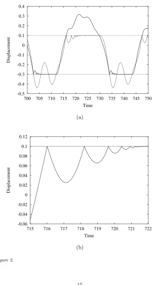
the displacement of both masses for this set of parameter values. The motion is period infinity steady state motion and each mass has a complete chatter sequence and sticking period during one excitation period. Complete chatter motions with sticking are referred to as period infinity periodic motions because an infinite number of instantaneous impacts occur in one period [16]. In Figure 2 (b) we show a close up of the chatter sequence computed for mass 2. The chatter peaks dimin-ish approximately exponentionally and can be studied via mappings [16, 17].
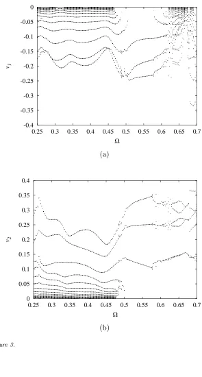
There is a special class of orbits which have a complete chatter sequence, but then lift off before a finite sticking time occurs — referred to as border orbits [17]. In vibro-impact systems these border orbits represent the boundary between the sticking and non-sticking regimes as a system parameter is varied. This can be seen in Figure 3 where examples of bifurcation diagrams for the two degree-of-freedom system with unequal constraints of different sign, computed for a forcing ampli-tudeA1= 0.5 are shown. In Figure 3 (a) the impact velocity,v1= ˙x1of mass 1 is shown against forcing frequency, Ω in the range 0.25–0.7, and in (b) the impact velocity, v2= ˙x2 is shown against the same frequency range. We note that because s1 < 0 the impact velocities for mass 1 are all less than zero, and likewise as s2 > 0 the impact velocities for mass 2 are all greater than zero.
The region of sticking motions all exist at forcing frequencies, Ω <
0.5, which can be seen from the chatter impact velocities successively decreasing toward zero. At low frequency, Ω < 0.5 periodic sticking motions preceded by complete chatter exist. Then as Ω is increased past the sticking region, chatter becomes incomplete – and the system passes through a border orbit. In fact careful observation shows that for mass 1, chatter remains incomplete for 0.3/Ω/0.35 and 0.37 /Ω/0.4, such that additional border orbits exist close to these parameter values. In Section 2.2 the relationshipFp= 0 was used to define the
bound-ary in phase space where sticking ends. For example, for the system shown in Figure 2, the case when x2 = s2 and ˙x2 = 0, the system trajectories during sticking will be restricted to the x1,x˙1 space. By setting Equation (23) to zero we define the relationship for the end of sticking as ˙x1 = −(k/c)x1 + (k/c)s2 = ˙x1 = −10x1 + 1, which defines the exit boundary of the sticking region S which is denoted
∂S. For sticking to exist the condition Fpsp > 0 must apply, which
in this case is the region on the positive side of the ∂S. Note also that ∂S includes the point (0.1,0) which corresponds to the (x2,x˙2) values during sticking. However, when mass 2 sticks, setting Equation (20) to zero results in a relationship for the end of sticking given by
˙
This exit boundary for the sticking region is now dependent of the forcing frequency Ω.
In the work on sliding orbits by [20], S was defined using Utkin’s equivalent control method. However, in this case only a subset of the system states are restricted to S, with the result that we cannot define
S simply in terms of the system parameters alone, we must include some of the system states.
3.3. Multiple nonsmooth events
Sliding bifurcations have been studied in detail for relay systems [20] and friction oscillators [24]. The occurrence of the multi-sliding bifur-cation in vibro-impact systems was first highlighted by [19] (referred to as a rising bifurcation) and has been studied for two degree-of-freedom systems by [21]. Multi-sliding occurs when a sliding orbit in the region
S becomes tangent (in a similar way to grazing) to the exit boundary
∂S as a system parameter is varied. In the system studied here ∂S is defined by the condition Fp = 0, and so we can characterize a
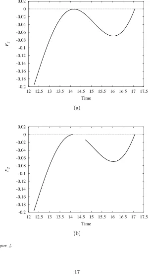
multi-sliding event using Fp. An example is shown in Figure 4, where the
forceF2 is shown just before, Figure 4 (a) and just after a multi-sliding bifurcation, Figure 4 (b). In both Figure 4 (a) and (b), the solid line represents the force on the mass during the sticking phase. In this example a negative force is required to keep mass 1 stuck to the motion constraint. So when the force signal intersects the zero axis, the mass lifts off from the constraint. In the special case when the force becomes tangent to the zero axis, a multi-sliding bifurcation occurs — Figure 4 (a). In Figure 4 (b), the situation just after multi-sliding is shown, where the sticking orbit is now divided into two segments. In between the segments a chatter sequence exists [21].
In addition to multi-sliding, other sliding bifurcations can occur in vibro-impact systems. For example, for the special case of r = 0, the system will have a grazing-sliding bifurcation each time a grazing event occurs — exceptions to this are discussed in [25]. This is similar to the grazing-sliding in the friction oscillator example studied by [24]. The non-generic example mentioned in section 2.2 of a mass coming into contact with the constraint with zero velocity and as the force changed sign, is also an example of grazing-sliding.
to list the possible combinations of multiple nonsmooth events in a two mass system.
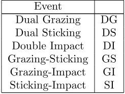
Table I.: Possible multiple nonsmooth events.
Event
Dual Grazing DG
Dual Sticking DS Double Impact DI Grazing-Sticking GS Grazing-Impact GI Sticking-Impact SI
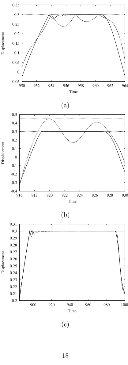
An example is shown in Figure 5 (a) where mass 1 has a complete chatter and sticking sequence, and mass 2 has two impacts during the sticking phase of mass 1 (SI), where both motion constraints are set at s1 = s2 = 0.3. This is distinct from a double impact (DI) which is the case where x1 = s1 and x2 = s2 simultaneously without chatter or sticking — a rare event. However, because our model of the impact assumes that an infinite number of impacts occur during sticking, the points in Figure 5 (a) could possibly be viewed as double impacts (DI) — i.e. both mass 1 and 2 are in contact with the motion constraints simultaneously. Despite this, it is preferable if a distinction between these two cases is made.
A second example is shown in Figure 5 (b), where the motion con-straint for mass 2 has been moved to s2 = 0.45, and the coefficient of restitution is close to zero (r = 0.001). In this case, mass 1 has a very short chatter sequence, and a long sticking phase. At t ≈ 920, mass 2 grazes with s2 = 0.45 while mass 1 is stuck (GS) — not the same as the grazing-sliding bifurcation — subsequent dynamics involve dual sticking of the masses (DS).
Finally in Figure 5 (c), an example is shown which is close to dual sticking (DS), at very low forcing frequency of Ω = 0.02, withr = 0.7. In this case mass 1 is stuck tos1, while mass 2 has a very long chatter sequence, and also appears to be stuck (at this scale), but in fact is still chattering at the end of the sticking phase of mass 1 — a reduction of Ω and/or r leads to the dual sticking case (DS).
4. Conclusions
systems. We have considered the mathematical modelling of these mul-tiple constraint systems using a modal formulation, including a modal form of the coefficient of restitution rule to model single, multiple and simultaneous impact events. The focus of this paper has been the chatter and sticking region for a two degree-of-freedom example. In particular we have discussed two types of sliding bifurcation — multi-sliding and grazing-sliding — which can occur in these systems.
The fact that the system considered has two masses means that nonsmooth events such as impact, grazing and sticking can occur si-multaneously for certain ranges of parameter values. The possible com-bination of these events has been discussed, and numerical simulations of three examples; impact and sticking, sticking and grazing and the dual sticking case have been presented.
Acknowledgements
References
1. Wagg, D. J. and Bishop, S. R. Dynamics of a two degree of freedom vibro-impact system with multiple motion limiting constraints,International Journal of Bifurcation and Chaos, 14(1): 119–140, 2004.
2. Shaw, J. and Shaw, S. W. , The onset of chaos in a two-degree of freedom impacting system, Journal of Applied Mechanics, 56: 168–174, 1989.
3. Hogan, S. J. and Homer, M. E. Graph theory and piecewise smooth dynamical systems of arbitrary dimension,Chaos, Solitons & Fractals, 10(11): 1869–1880, 1999.
4. Lenci, S. and Rega, G., Regular nonlinear dynamics and bifurcations of an impacting system under general periodic excitation, Nonlinear Dynamics, 34: 249–268, 2004.
5. Masri, S. F. Theory of the dynamic vibration neutraliser with motion-limiting stops,Transactions of the American Society of Mechanical Engineers, Journal of Applied Mechanics, 39: 563–568, 1972.
6. Chatterjee, S. and Mallik, A. K. and Ghosh, A., On impact dampers for non-linear vibrating systems, Journal of Sound and Vibration, 187(3): 403–420, 1995.
7. Neilson, R. D. and Gonsalves, D. H., Chaotic motion of a rotor system with a bearing clearance, Applications of fractals and chaos, A. J. Crilly and R. A. Earnshaw and H. Jones, Springer-Verlag, 285–303, 1993.
8. Theodossiades, S. and Natsiavas, S., Periodic and chaotic dynamics of motor-driven gear-pair system with backlash,Chaos, Solitons and Fractals, 12: 2427– 2440,2001.
9. Cusumano, J. P. and Bai, B-Y. Period-infinity periodic motions, chaos and spatial coherence in a 10 degree of freedom impact oscillator, Chaos, Solitons and Fractals, 3: 515–536, 1993.
10. Nigm, M. M. and Shabana, A. A. Effect of an impact damper on a multi-degree of freedom system, Journal Of Sound and Vibration, 89(4): 541–557, 1983. 11. Pfeiffer, F. and Glocker, C. Multibody dynamics with unilateral contacts, John
Wiley,1996.
12. Natsiavas, S. Dynamics of multiple-degree-of-freedom oscillators with colliding components, Journal of Sound and Vibration, 165(3): 439–453, 1993.
13. Pun, D. and Lua, S. L. and Law, S. S. and Cao, D. Q., Forced vibration of a multidegree impact oscillator, Journal of Sound and Vibration, 213(3): 447–466, 1998.
14. Shaw, S. W. and Holmes, P. J., A periodically forced piecewise linear oscillator,
Journal of Sound and Vibration, 90(1): 129–155, 1995.
15. Luo, G. W. and Xie, J. H. Hopf bifurcations and chaos of a two-degree-of-freedom vibro-impact system in two strong resonance cases, Non-linear Mechanics, 37: 19–34, 2002.
16. Budd, C. J. and Dux, F., Chattering and related behaviour in impact os-cillators, Philosophical Transactions of the Royal Society of London A, 347: 365–389, 1994.
19. Toulemonde, C. and Gontier, C Sticking motions of impact oscillators,
European Journal of Mechanics A:Solids, 17(2): 339–366, 1998.
20. Di Bernardo, M. and Johansson, K. H. and Vasca, F., Self-oscillations and sliding in relay feedback systems:symmetry and bifurcations, International Journal of Bifurcation and Chaos, 4(11): 1121–1140, 2001.
21. Wagg, D. J. Rising phenomena and the multi-sliding bifurcation in a two-degree of freedom impact oscillator, Chaos, Solitions and Fractals, 22(3): 541–548, 2003.
22. Meirovitch, L. Analytical methods in vibration, McGraw-Hill: New York, 1967. 23. Thompson, J. M. T. and Stewart, H. B., Nonlinear dynamics and chaos, John
Wiley: Chichester, 2002.
24. Di Bernardo, M. and Kowalczyk, P. and Nordmark, A., Sliding bifurcations: A novel mechanism for the onset of chaos in dry friction oscillators, International Journal of Bifurcation and Chaos, 13(10): 2935–2948, 2003.
Figure Captions
− Figure 1. Schematic representation of an impact oscillator with multiple motion limiting constraints (a) N degree-of-freedom (b) a 2 degree-of-freedom.
− Figure 2. Numerically computed displacement time series of a two degree-of-freedom impact oscillator with constraintss1=−0.3 and
s2= 0.1; Solid line mass 1; dashed line mass 2. (a) showing chatter and sticking motion. (b) close up of the chatter region for mass 2.
− Figure 3. Numerically computed two degree-of-freedom impact os-cillator bifurcation diagram for case (b) with impact stops s1 =
−0.3,s2 = 0.1. Parameter values m1 = m2 = 1, k1 = k2 = 1,
c1 = c2 = 0.1, r = 0.7, forcing A2 = 0.0, A1 = 0.5. (a) Impact velocityv1vs forcing frequency Ω. (b) Impact velocityv2vs forcing frequency Ω.
− Figure 4 Multi-sliding bifurcation. ForceF2during a sticking phase of mass one. (a) Just before multi-sliding Ω = 0.256, (b) just after multi-sliding Ω = 0.2561.
m1 m2
k k
c c
s s
1 1
1 1 1
2 2
2 2 2
f
x fx
mN
sN x fN
N
(a)
m1 m2
k k
c c
s s
1 1
1
1 1
2 2
2 2 2 f
x fx
[image:15.595.133.466.221.581.2](b)
-0.5 -0.4 -0.3 -0.2 -0.1 0 0.1 0.2 0.3 0.4
700 705 710 715 720 725 730 735 740 745 750
Displacement
Time
(a)
-0.06 -0.04 -0.02 0 0.02 0.04 0.06 0.08 0.1 0.12
715 716 717 718 719 720 721 722
Displacement
Time
[image:16.595.140.442.117.679.2](b)
-0.4 -0.35 -0.3 -0.25 -0.2 -0.15 -0.1 -0.05 0
0.25 0.3 0.35 0.4 0.45 0.5 0.55 0.6 0.65 0.7
v1
Ω
(a)
0 0.05 0.1 0.15 0.2 0.25 0.3 0.35 0.4
0.25 0.3 0.35 0.4 0.45 0.5 0.55 0.6 0.65 0.7
v2
Ω
[image:17.595.145.440.123.673.2](b)
-0.2 -0.18 -0.16 -0.14 -0.12 -0.1 -0.08 -0.06 -0.04 -0.02 0 0.02
12 12.5 13 13.5 14 14.5 15 15.5 16 16.5 17 17.5
F2
Time
(a)
-0.2 -0.18 -0.16 -0.14 -0.12 -0.1 -0.08 -0.06 -0.04 -0.02 0 0.02
12 12.5 13 13.5 14 14.5 15 15.5 16 16.5 17 17.5
F2
Time
[image:18.595.142.445.131.693.2](b)
-0.05 0 0.05 0.1 0.15 0.2 0.25 0.3 0.35
950 952 954 956 958 960 962 964
Displacement
Time
(a)
-0.4 -0.3 -0.2 -0.1 0 0.1 0.2 0.3 0.4 0.5
916 918 920 922 924 926 928 930
Displacement
Time
(b)
0.2 0.21 0.22 0.23 0.24 0.25 0.26 0.27 0.28 0.29 0.3 0.31
900 920 940 960 980 1000
Displacement
Time
[image:19.595.191.400.101.694.2](c)