White Rose Research Online
[email protected]
Universities of Leeds, Sheffield and York
http://eprints.whiterose.ac.uk/
This is a copy of the final published version of a paper published via gold open access
in
International Journal of Material Forming
.
This open access article is distributed under the terms of the Creative Commons
Attribution Licence (
http://creativecommons.org/licenses/by/4.0/
) which permits
unrestricted use, distribution, and reproduction in any medium, provided the
original work is properly cited.
White Rose Research Online URL for this paper:
http://eprints.whiterose.ac.uk/87037
Published paper
THEMATIC ISSUE: FLEXIBLE FORMING - INCREMENTAL SHEET FORMING & ROLL FORMING
Titanium based cranial reconstruction using incremental sheet
forming
B. Lu&H. Ou&S. Q. Shi&H. Long&J. Chen
Received: 21 August 2014 / Accepted: 1 December 2014
#The Author(s) 2014. This article is published with open access at Springerlink.com
Abstract In this paper, we report recent work in cranial plate manufacturing using incremental sheet forming (ISF) process. With a typical cranial shape, the ISF process was used to manufacture the titanium cranial shape by using different ISF tooling solutions with and without backing plates. Detailed evaluation of the ISF process including material deformation and thinning, geometric accuracy and surface finish was conducted by using a combination of experimental testing and Finite Element (FE) simulation. The results show that satisfactory cranial shape can be achieved with sufficient accuracy and surface finish by using a feature based tool path generation method and new ISF tooling design. The results also demonstrate that the ISF based cranial reconstruc-tion has the potential to achieve considerable lead time reduction as compared to conventional methods for cranial plate manufacturing. This outcome indicates that there is a potential for the ISF process to achieve technological ad-vances and economic benefits as well as improvement to quality of life.
Keywords Incremental sheet forming . Cranial plate reconstruction . Finite element
Introduction
Cranioplasty is a surgical procedure for the repair of deformity of a human skull due to brain tumour, stroke or traumatic injuries. Cranioplasty surgery does not only offer cosmetic and sometimes lifesaving benefits but also give relief to psy-chological drawbacks and improve the quality of life of pa-tients [1]. Cranioplasty surgical procedures may be conducted by using autografting (implant taken from patient own body) and allografting (implant taken from a donor body) or alloplastic (non-biologic such as polymeric and metallic) ma-terials. Non-metallic materials such as Polymethyl-methacrylate (PMMA), Polyetheretherketone (PEEK) and Hydroxyapatite, and metallic substitutes such as stainless steel and titanium, alloplastic materials are commonly used in cranioplasty surgeries. The selection of cranioplasty materials is normally based on the requirements of such as biocompat-ibility, material properties and surgeon’s experience and pref-erence. Technical readiness for clinical application, short lead time, low cost and ease of manufacture for alloplastic cranioplasty are also important considerations [2].
Among all alloplastic materials including PMMA and PEEK, titanium continues to be the main stream material used in cranioplasty surgeries because of its excellent biocompati-bility, resistance to infection, excellent material property, strength and lightweight. However, in spite of the common use and increasing need for titanium based cranial reconstruc-tion, there is a wide variety of methods including casting [3], manual shaping [4,5] and rubber press forming [6–8] com-monly used in the manufacture of cranial reconstruction. Even with the assistance of advanced CAD/CAM (computer-aided design and manufacture), computed tomographic (CT) and magnetic resonance imaging (MRI) technologies [2,3,6–8], the processes needed to manufacture customised casting moulds, templates and forming dies in conventional methods of cranial manufacturing is not only costly but also time
B. Lu
:
J. ChenDepartment of Plasticity Technology, Shanghai Jiao Tong University, 1954 Huashan Road, Shanghai 200030, People’s Republic of China
H. Ou (*)
:
S. Q. ShiDepartment of Mechanical, Materials and Manufacturing
Engineering, University of Nottingham, Nottingham NG7 2RD, UK e-mail: [email protected]
B. Lu
:
H. LongDepartment of Mechanical Engineering, University of Sheffield, Sheffield S1 3JD, UK
Int J Mater Form
consuming often normally requiring a few days up to 2 weeks to completion depending on considerations of such as techni-cal planning and whether there is a case of surgitechni-cal urgency [2,
6,7]. In recent years, 3D printing or additive manufacturing based technologies have made rapid advances and it is possi-ble to complete the 3D printing of a cranial or a maxillofacial prosthetic part within several hours [9,10]. However, there are still a number of impediments including insufficient material properties and high cost issues to be overcome before its wide adoption for clinical applications [11].
The ISF process is centred on material plastic deformation of symmetric and asymmetric shapes of sheet metals by tracing a rotational tool along a sequence of contour lines generated directly from part CAD model [12]. Its excellent adaptability to CNC (Computer Numerical Control) systems through direct control of CAD data, with the minimum use of complex tooling, dies and forming press, makes the process cost-effective and easy to automate and adapt for various applications. The localised plastic deformation taking place incrementally ensures improved material formability and this makes it suitable for a wide range of sheet metal materials including titanium. Therefore, it is particularly attractive for manufacturing high value-added, small batch and customised sheet parts. In the past decade, significant progress has been made in the research of ISF technology. In the ISF process development, conventional single point incremental forming (SPIF) [13], two-point incremental forming (TPIF) [14], hy-brid forming by combining stretch forming and incremental sheet forming [15] and double side incremental forming (DSIF) [16] have been developed in recent years. Concerning the deformation and fracture mechanisms, differ-ent theories including bending under tension(BUT) [17], through-thickness shear effect [18,19] and the“noodle theo-ry”[20] has been proposed. The forming accuracy and the surface finish of the final part have also been investigated [21,
22]. Thanks to these efforts, the application of ISF technology in the real-world becomes possible.
In the application of the ISF technology, the ad-vances of ISF make it specially suitable for manufacture small-batch or customised components, such as those in automobile [23], aerospace [24] and medical application [25]. In a recent paper, effort was made to use ISF to manufacture cranial reconstruction [26]. Whilst the study demonstrated the soundness of ISF based ap-proach for cranial manufacturing, unintended failures in forming high wall angle cranial shape and insuffi-cient accuracy of the formed cranial plate were encoun-tered. From the skull geometry of a patient to a manufactured cranial plate, a few challenges still exist including the formability of material, the geometric con-struction with ISF toolpath generation, the geometric accuracy and the final surface finish of the cranial plate. Although these topics may have been individually
examined in the past of ISF research, these challenges need to be further investigated for the potential practical application in cranial reconstruction.
T h i s p a p e r a i m s to s t u d y t h e f e a s i b i l i t y o f manufacturing customized titanium cranial plates by using the ISF approach. In this paper, the material properties of Grade 1 pure (TA1)titanium sheets were firstly investigated. To evaluate the friction effect be-tween the tool and sheet, both conventional ball-head rigid tool and a roller ball tool were employed in the forming process and the surface finish after ISF process was examined. By taking a typical cranial shape, the cranial geometric shape for ISF processing was con-structed and the tool path was generated. With the support of FE simulation, a series of ISF experiments were carried out to examine the feasibility of incremen-tal sheet forming for manufacturing cranial plates. By investigating the forming load, material deformation with consideration of thickness distribution and surface finish, a detailed assessment of the ISF based cranial reconstruction is conducted. This is followed by con-cluding remarks for future work.
Material and methods
Material properties of (TA1) titanium sheets
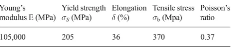
[image:3.595.307.545.664.713.2]TA1 titanium material contains 99.67 % of titanium, 0.08 % of carbon and 0.03 % of iron and 0.22 % of other compositions such as oxygen and hydrogen. Table1 shows the material properties of TA1 pure titanium.Concerning the ISF processing of TA1 material, from the manufacturing point of view, the flow stress and material ductility are the two key factors that affect the ISF process: the flow stress including the initial yielding and strain hardening which determine the forming load and corresponding contact pres-sure between tool-sheet interfaces. Although it is proven that ISF enables enhanced formability, the ductility of material is still a key factor that would affect the potential ISF formability, which is important for the successful im-plementation of incremental forming. In this work, the material properties of TA1 titanium material are examined by using tensile tests on an Instron tensile testing machine, as shown in Fig. 1.
Table 1 Material properties of TA1 pure titanium
Young’s modulus E (MPa)
Yield strength
σS(MPa)
Elongation
δ(%)
Tensile stress
σb(Mpa)
Poisson’s ratio
Figure2shows the flow stress of TA1 titanium. As can be seen from the figure, the initial yield stress is about 200 MPa while the stress at fracture is about 350 MPa due to strain hardening. Concerning the material ductility, TA1 titanium shows good elongation property in the tensile test. Although the measured elongation is different, the minimum value can be over 35 %, which indicates good material formability in incremental sheet forming process. Based on this elongation, the maximum achievable ISF forming angle may be up to 40° by calculation from Sine law. With the consideration of in-creased formability in ISF process comparing to tensile test, the maximum achievable forming angle is even higher in a single pass ISF process. The tensile test results suggested a good potential of this material to be used in ISF process.
Evaluation of friction between tool and sheet
The severe contact condition between the tool and sheet could cause rough surface finish of the cranial plate after ISF process. In order to solve this problem, instead of using the conventional ball head rigid tool, a roller ball tool could be a better option to the conventional tool for the material such as pure titanium that is easy to be
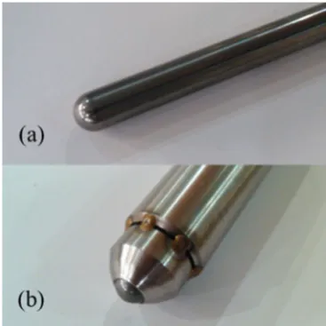
scratched. In this way, the conventional sliding friction condition in the ISF process can be replaced by the rolling friction condition, which proves to be effective preventing the potential scratch of the sheet surface in ISF processing [19]. Figures3 and4show the two types of tools used in incremental forming of the cranial plates.
Geometric definition and ISF tool path generation
Generation of the ISF toolpath is a key step for ISF based cranial reconstruction. In the conventional ISF technology, toolpaths may be generated directly through CAD-based freeform surface or discrete surface represented by STereoLithography (STL). In practical application for cranioplasty, the geometric data of a skull shape to be reconstructed are typically from the point cloud from CT scan for subsequent model repair [27]. Concerning the technical approach based on the scanned points cloud, the toolpath generation via STL model seems to
Fig. 1 Tensile test of TA1 titanium sheet
Fig. 2 Flow stress of TA1 titanium
Fig. 3 ISF tools for cranial plate forming:aconventional ball-head rigid tool;broller-ball tool
[image:4.595.233.540.51.215.2] [image:4.595.332.516.506.690.2] [image:4.595.52.288.550.702.2]be more convenient than the approach of free form surface generation as the reverse engineering technique can be avoided in reconstructing the CAD surface through point cloud. In this work, a cranial shape from a human skull of point cloud was employed. Although model repair may be required due to traumatic tissue loss in some cases, no model repair is implemented in this work and the surface model is directly taken from the top of the cranium as a demonstration of the ISF based cranial reconstruction technique.
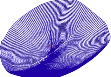
Based on the geometrical shape of the cranial plate, an offset model with consideration of tool radius was established. Spiral tool paths with scallop height of 0.005 mm are generated based on the z-level slicing approach described in authors’ previous work [22]. In the z-level slicing approach, the toolpaths are generated by interpolation to the contour lines of the model in the vertical direction. Figure 5 shows the toolpath generated for ISF processing of the cranial plate. By considering the total length of the toolpath and a feed rate of 2000 mm/min, the whole ISF process for the cranial plate manufacturing requires 12 min to complete, which is generally much more efficient than many convention-al forming based techniques for craniconvention-al reconstruction where additional dies and moulds are necessary.
FE modelling
As an effective method for analysing material deforma-tion and other concerned issues such as accuracy and material thinning and strain distribution of the work-piece, FE method was used to investigate the sheet deformation in ISF processing for the cranial plate. In this work, ABAQUS Explicit software package was employed. Using the flow stress results obtained from the tensile test and the toolpath generated based on the cranial geometry, an FE model was built as shown in Fig. 6. As shown in the figure, a roller-ball tool with diameter of 10 mm other than the conventional rigid tool was employed in the ISF simulation. The 10 mm wide purple region to the edge of the blank was constrained to represent the clamping of the workpiece onto the fixture. The friction coefficient was set to be 0.05 for the contacts between the tool and sheet [28]. A backing plate is placed underneath the sheet to support the part. The mesh size is 1 mm with approximately 50,000 elements. The original feed rate of the tool was set to be 2000 mm/min. However, in order to improve the simulation efficiency, the virtual forming speed was scaled up by 100 times according to the best practice
(a) Skull model (b) Cranial model taken for ISF construction
Fig. 4 Geometric construction for cranial plate model.aSkull modelbCranial model taken for ISF construction
[image:5.595.231.545.53.191.2] [image:5.595.310.547.564.699.2] [image:5.595.79.263.570.697.2][28], in which the ratio of kinematic energy to total energy can be controlled within a limited value. By using this model, the ISF process for cranial plate construction can be analysed and the simulation results compared with experiment.
Experimental setup
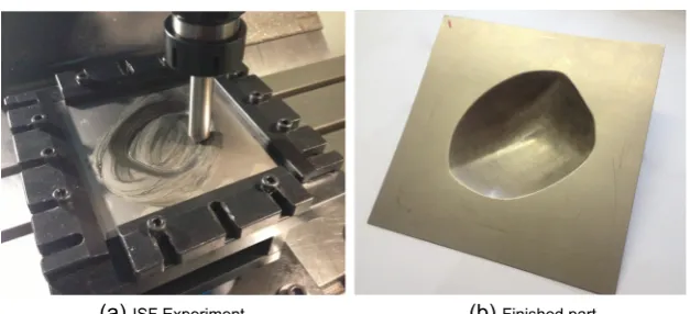
To facilitate the incremental forming for the cranial plate, ISF experiments were conducted by using a 3-axis milling machine. Figure 7 shows the setup of the ISF process and one of the formed cranial plates with the roller ball tool. TA1 titanium sheet with a thickness of 0.5 mm was used for ISF based forming of the cranial plate. Both conventional ball-head rigid tool and the roller ball tool, as shown in Fig. 3 were used for comparison. Rocol RTD compound was employed as the lubricant during the forming process. The tool path generated in Section 2.3 was converted to NC code and the forming tool moved along this pre-defined path during the ISF process. The feed rate of the tool was
set to be 2000 mm/min during forming. During the ISF experiment, a multi-axis JR3 load cell was employed to measure the forming forces during the ISF process.
Results and discussion
Forming forces
The forming forces from both FE simulation and experiment were obtained as shown in Fig. 8. As can be seen from the figure, similar trend of forming load variations can be ob-served. The forming loads increase rapidly to its maximum value at the initial forming stage and gradually drop down in the forming process. This variation is depended upon the forming shape and the step down value of the forming path. By examining the maximum forming load, in vertical tion, the value reaches 500 N, while in the horizontal direc-tion, the maximum forming load is 300 N. This result suggests that comparing to other methods such as stamping, the
(a) ISF Experiment (b) Finished part Fig. 7 ISF experiments of cranial
plate formingaISF experimentb
Finished part
Fig. 8 Comparison of forming load
[image:6.595.232.546.51.194.2] [image:6.595.233.547.531.712.2]forming load is relatively small by using the ISF process for cranial plate manufacturing. In addition, the similarity of forming load from both FE and ISF experimental results suggests that the FE model can be used to provide an accurate prediction of the ISF process for cranial plate manufacturing.
Sheet deformation
Using the FE model, the strain and thickness distributions of the finished cranial part are obtained. As shown in Figs.9and10,
the maximum deformation occurs at the edge of the cranial plate model, where it has the largest wall angle. With the forming process continues, the slope of the wall angle becomes more gradual so the material deformation is less severe.
Sheet thickness
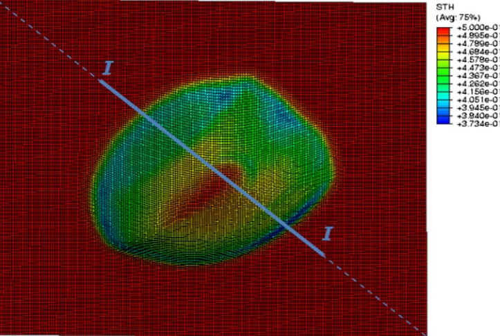
By examining the thickness distribution obtained from FE simulation, it tends to have the similar variation trend to the material deformation as shown in Fig. 10. With an initial
[image:7.595.181.541.52.289.2]Fig. 9 Distribution of equivalent strain
[image:7.595.181.543.468.711.2]thickness of 0.5 mm, the minimum wall thickness is about 0.37 mm resulting in a 26 % reduction. The maximum thick-ness reduction occurs at the edge of the cranial plate whilst in the bottom region, the sheet becomes less deformed. To val-idate the calculated thickness distribution, the formed cranial parts processed by both the roller-ball and rigid tools were measured by a Mitutoyo CMM Euro-C-A121210coordinate measurement machine (CMM) and the thickness along sec-tionI-I was obtained and compared with the FE results as shown in Fig.11. As can be seen from the figure, both the rigid and roller-ball tool types produce almost identical thick-ness distributions. In addition, similar results between FE and experimental results can also be observed. The minimum measured thickness is 0.368 mm, which is very close to the FE thickness result of 0.373 mm. This comparison also sug-gests the accuracy of FE prediction.
Geometric accuracy
Both the finished parts before and after trimming of the blank from experimental approach were measured by using a
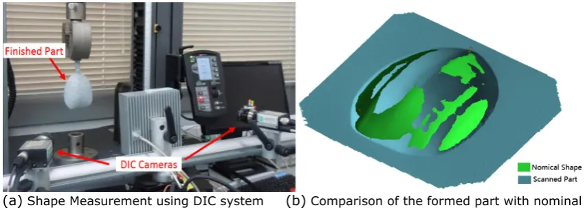
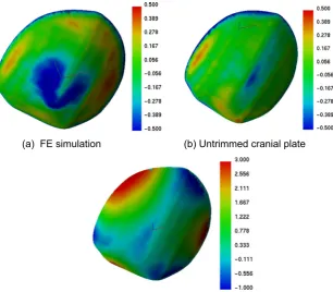
[image:8.595.230.544.59.207.2]Dantec Q-400 digital image correlation (DIC) system, as shown in Fig. 12, and the scanned point clouds were then reconstructed to STL model so the geometric accuracy of the ISF formed cranial plates can be evaluated by comparing to the nominal shape. Figure13shows the geometrical deviation from the nominal shape of parts from both FE and experi-mental testing. By comparing Fig.13a and b, it can be found some notable geometric difference between FE and experi-mental results. The maximum difference is in the region of the bottom of the part reaching 0.5 mm. This discrepancy may be due to the inaccurate prediction of material springback in FE explicit simulation. Concerning the devia-tion of the actual cranial plate geometry from the nominal shape, it can be found that the maximum deviation is from the edge of the part with a magnitude of 0.5 mm. By measuring the deviation of the trimmed part as shown in Fig. 13c, obvious springback can be observed after removing the blank. The maximum deviation occurs along the trimmed edge with the value of about 3 mm. This springback may be due to the reduced stiffness around the edge after trimming and re-distribution of residual stress. This result suggested
Fig. 11 Thickness distribution along sectionI-I
(a) Shape Measurement using DIC system (b) Comparison of the formed part with nominal
shape
Fig. 12 Measurement and evaluation of finished cranial plate.aShape measurement using DIC systembComparison of the formed part with nominal shape
[image:8.595.83.509.529.682.2]that geometric inaccuracy of the cranial plate after the ISF processing and trimming needs to be compensated for to a smaller amount. Further optimisation on ISF toolpath strate-gies and ISF specific compensation methods may be used to minimise the springback due to such as residual stress redis-tribution. Alternatively it is possible to manually correct the shape deviation to an acceptable level for cranial reconstruc-tion before more robust optimisareconstruc-tion and compensareconstruc-tion ap-proaches may be developed [4,5].
Surface finish
The surface finish of the ISF processed cranial plates can be examined as shown in Fig.14. Obvious galling can be observed
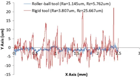
on the part surface processed by the rigid tool. This is due to the adherence of the titanium sheet onto the tool surface and these adhesions further scratch the part surface. Concerning the part processed by the roller ball tool, although tool marks may still be visible, the surface finish is much improved and no adhesion on the part surface can be observed. The detailed surface profiles were examined by using a surface roughness measure-ment machine as shown in Fig. 15. Obvious difference of profiles can be observed. TheRzvalue of the part processed
by the rigid tool is 25.7μm as compared to that of 5.7μm processed by the roller ball tool. As given in same the figure, similar proportion of difference of the Ravalue is obtained. This
result further proves that substantial surface roughness im-provement may be made by using the roller-ball tool.
(a) FE simulation (b) Untrimmed cranial plate
[image:9.595.237.544.53.321.2](c) Trimmed cranial plate
Fig. 13 Geometrical deviation of finished part.a FE simulationb
Untrimmed cranial platec
Trimmed cranial plate
(a) Rigid tool (b) Roller ball tool
Fig. 14 Surface examination of roller-ball tool and rigid toola
[image:9.595.234.545.569.708.2]General assessment of ISF based methods for reconstruction of cranial plates
By evaluating the feasibility and challenges for ISF based cranial reconstruction, this study confirms that the titanium sheet can be produced for cranioplasty applications by using the ISF approach. Comparing to the conventional approaches such as stamping, ISF does not require the preparation of shape specified forming tools, which not only reduces the cost but also the forming time. The localized deformation of the workpiece ensures the enhanced deformation stability and sheet formability as compared to conventional forming methods. By employing the roller ball tool, the surface finish of the formed part can be significantly improved to meet the requirement for surgical operations. Concerning the geometric accuracy, a maximum 3 mm springback of the trimmed part can be observed at the edge of cranial plate after removal of the blank. As the cranial plate is a thin-wall part with thickness of about 0.5 mm or less, the stiffness may not be large enough to maintain its original shape during the re-distribution of residual stress in the blank trimming. For clinical implemen-tation of the ISF process in cranial plate manufacturing, three specific aspects need to be considered:
1) Processing technology: In ISF processing of the cranial plate a pre-prepared backing plate was employed in the forming process. A customized backing plate needs to be made to ensure the ISF geometric accuracy. Thus this is still not an entirely“flexible”process. In the future de-velopment, a more advanced DSIF (double side incre-mental forming) technology with a forming tool and a counter tool may be employed to replace the current technology framework of forming tool i.e. the use of a backing plate. Such a solution would further increase the process flexibility and automation.
2) Lubrication: It was found that pure titanium is easy to adhere to the forming tool so roller-ball type tools with lubricants were employed in the experiments. Although surface cleaning process is employed in clinical
application, development of new roller ball tool with self-lubricant coating or non-metallic tools to avoid ISF tool and workpiece adhesion would be beneficial for less demand in cranial plate sterilisation.
3) Geometric accuracy: The springback during the trimming of the blank is considerably large. This kind of springback may not be easily avoided as the cranial plate is a thin sheet and the tensile strength of titanium is relatively high. Therefore, for full clinical application of ISF based cranial reconstruction, it is important to develop more robust toolpath strategies to achieve uniform residual stress dis-tribution and to establish more rigorous optimisation and compensation methods for accurate quantification and efficient minimisation of part springback with a given size and shape of cranial plate.
Conclusions
In this work, by evaluating the material properties of Grade 1 pure titanium sheets, FE simulation and ISF experimental testing for cranial plates, the feasibility of manufacturing customized titanium cranial plates by using the ISF approach is studied and the particular issues and possible solutions were discussed. The conclusions of this work may be summarized as follows:
1) ISF based construction of cranial plate by using Grade 1 pure titanium sheets is a feasible solution and it shows clearly the potential for real medical application.
2) The surface finish and thickness distribution are satisfac-tory for the application of cranioplasty.
3) Further development is still needed to overcome few specific issues including the current use of backing plate and lubricant, the requirement for new tools as well as the minimisation of springback.
Acknowledgment The authors are grateful for the support provided by the Engineering and Physical Science Research Council of UK (EP/ L02084X/1) and the Marie Curie International Incoming Fellowship (628,055 & 913,055) and International Research Staff Exchange Scheme (IRSES, MatProFuture project, 318,968) within the 7th EC Framework Programme (FP7). The authors wish to thank Dr Mingjun Liu of Cranioplasty Unit, The University College London Hospitals NHS Foun-dation Trust for reviewing the manuscript and for providing valuable suggestions in cranioplasty, Mr Tom Edgar of Queen’s University Belfast for providing the geometric model of the skull for cranial reconstruction; Mr Tom Buss, Jason Young and Mark Daine of University of Nottingham for their support in material testing and cranial plate measurements.
[image:10.595.51.288.52.185.2]Open AccessThis article is distributed under the terms of the Creative Commons Attribution License which permits any use, distribution, and reproduction in any medium, provided the original author(s) and the source are credited.
Fig. 15 Comparison of surface profiles of parts processed by roller-ball tool and rigid tool
References
1. Aydin S et al (2011) Cranioplasty: Review of materials and tech-niques. J Neurosci Rural Pract 2(2):162–167
2. Spetzger U, Vougioukas V, Schipper J (2010) Materials and tech-niques for osseous skull reconstruction. Minim Invasive Ther Allied Technol 19:110–121
3. Heissler E et al (1998) Custom-made cast titanium implants produced with CAD/CAM for the reconstruction of cranium defects. Int J Oral Maxillofac Surg 27(5):334–338
4. Bartlett P, Carter LM, Russell JL (2009) The Leeds method for titanium cranioplasty construction. Br J Oral Maxillofac Surg 47(3):238–240
5. Bhargava D et al (2010) Construction of titanium cranioplasty plate using craniectomy bone flap as template. Acta Neurochir 152(1): 173–176
6. Joffe J et al (1999) A prospective study of computer-aided design and manufacture of titanium plate for cranioplasty and its clinical out-come. Br J Neurosurg 13(6):576–580
7. Day RE et al (2012) The Royal Perth Hospital method for the design and manufacture of titanium cranioplasty plates. Br J Oral Maxillofac Surg 50:376–377
8. Lieger O et al (2010) Computer-assisted design and manufacture of implants in the late reconstruction of extensive orbital fractures. Arch Facial Plast Surg 12(3):186–191
9. Rotaru H, et al. Cranioplasty With Custom-Made Implants: Analyzing the Cases of 10 Patients. Journal of Oral and Maxillofacial Surgery.70(2): p. e169-e176
10. Klein GT, Lu Y, Wang MY (2013) 3D Printing and Neurosurgery— Ready for Prime Time? World Neurosurg 80(3):233–235
11. Elahinia MH et al (2012) Manufacturing and processing of NiTi implants: A review. Prog Mater Sci 57(5):911–946
12. Jeswiet J (2005) Asymmetric Incremental Sheet Forming. Adv Mater Res 6–8:35–58
13. Iseki H, Kato K, and Sakamoto S (1389)Flexible and incremental sheet metal forming using a spherical roller.In: Proc. 40th JJCTP: p. 41–44 (in Japanese).
14. Matsubara S (1994) Incremental Backward Bulge Forming of a Sheet Metal with a Hemispherical Head Tool. J JSTP 35(406):1311–1316
15. Araghi BT et al (2009) Investigation into a new hybrid forming process: Incremental sheet forming combined with stretch forming. CIRP Ann Manuf Technol 58(1):225–228
16. Malhotra R et al (2010) Improvement of Geometric Accuracy in IncrementalForming by Using a Squeezing Toolpath Strategy with Two Forming Tools. J Manuf Sci Eng 133(6):603–611
17. Emmens WC, Boogaard AH (2008) Tensile tests with bending: a mechanism for incremental forming. Int J Mater Form 1(1):1155–1158 18. Allwood JM, Shouler DR (2009) Generalised forming limit diagrams showing increased forming limits with non-planar stress states. Int J Plast 25(7):1207–1230
19. Lu B et al (2014) Mechanism investigation of friction-related effects in single point incremental forming using a developed oblique roller-ball tool. Int J Mach Tools Manuf 85:14–29
20. Malhotra R et al (2012) Mechanics of fracture in single point incre-mental forming. J Mater Process Technol 212(7):1573–1590 21. Micari F, Ambrogio G, Filice L (2007) Shape and dimensional
accuracy in Single Point Incremental Forming: State of the art and future trends. J Mater Process Technol 191(1–3):390–395
22. Lu B et al (2013) Feature-based tool path generation approach for incremental sheet forming process. J Mater Process Technol 213(7): 1221–1233
23. Lievers WB, Pilkey AK, Lloyd DJ (2004) Using incremental forming to calibrate a void nucleation model for automotive aluminum sheet alloys. Acta Mater 52(10):3001–3007
24. Hussain G et al (2012) Guidelines for Tool-Size Selection for Single-Point Incremental Forming of an Aerospace Alloy. Mater Manuf Process 28(3):324–329
25. Ambrogio G et al (2005) Application of Incremental Forming process for high customised medical product manufacturing. J Mater Process Technol 162–163:156–162
26. Duflou JR et al (2013) Manufacture of Accurate Titanium Cranio-Facial Implants with High Forming Angle Using Single Point Incremental Forming. Key Eng Mater 549:223–230
27. Scholz M et al (2007) Reconstruction of the temporal contour for traumatic tissue loss using a CAD/CAM-prefabricated titanium implant-case report. J Cranio-Maxillofac Surg 35(8):388–392 28. Fang Y et al (2014) Analytical and experimental investigations on