Development of thermoacoustic devices
for power generation and refrigeration
Artur J Jaworski and Xiaoan Mao
Abstract
This paper is intended as a technical overview of the research and development work initially undertaken at the University of Manchester and subsequently transferred to the University of Leicester as part of the EPSRC-funded SCORE project (Stove forCooking,Refrigeration andElectricity supply). The objectives of the work were twofold: Firstly, to develop an early demonstrator of a low-power electricity generator (to deliver approximately 10–20 W of electricity). This was to be based on the concept of using low-cost materials, working fluids and linear alternators suitable for deployment in rural areas of developing countries. The issues of concern here were the development of a suitable thermoacoustic engine topology and control measures; design of suitable heat exchanger configurations from initial use of electrical heaters to heat input through propane combustion; and characterisation of commercial loudspeakers to work as linear alternators and subsequent incorporation of selected models for engine prototyping purposes. These matters will be illustrated by a number of demonstrators and their testing in the laboratory environment. Secondly, to develop a demonstrator of a combustion driven thermoacoustic cooler for storage of vital medical supplies in remote and rural areas where there is no access to electricity grid. To this end, the paper will describe the design, construction and test results of an electrically driven demonstrator of a standing wave thermoacoustic engine coupled to a travelling wave thermoacoustic cooler. The final part of the paper will summarise the achievements to date and outline future work that has spun out from the original SCORE project. This will in particular include the current work on a scaled up version of electricity generator designed to deliver 100 W of electricity by using a two-stage engine configuration and the issues of integration of the thermoacoustic electricity generator and thermoacoustic cooler into one system.
Keywords
Advanced power cycles, biomass, energy conversion/recovery, engine testing, heat exchangers, heat recovery, power from waste and biomass, power generation, shell/tube heat exchanges, Stirling engines, thermoacoustic refrigeration
Date received: 13 December 2012; accepted: 21 May 2013
Introduction
Thermoacoustic technologies deal with the conversion between heat and acoustic power by relying on the so-called ‘‘thermoacoustic effect’’. When a gas parcel undergoes the acoustic oscillations, it experiences a pressure change and a displacement from the equilib-rium position. If the gas parcel is close to a solid material which possesses a temperature gradient, heat transfer could take place between the gas parcel and the adjacent solid material due to a local tempera-ture difference. Hence, the appropriately phased pres-sure and displacement oscillations would enable the gas parcel to complete a useful thermodynamic cycle and thus to produce acoustic power by taking heat from the source at a higher temperature or to trans-port heat against the temperature gradient while con-suming the acoustic power. These effects lead to two practical engineering implementations. One is to
impose an appreciable temperature gradient within the solid material. This results in the spontaneous gen-eration of an acoustic wave along the direction of temperature gradient. Conversely, one could impose an acoustic wave in the compressible fluid, which would lead to hydrodynamic heat pumping effects along the solid material in the acoustic field. This results in the generation of a temperature gradient. These two interactions form the basis for engineering thermoacoustic engines and coolers (or heat pumps), respectively.
Department of Engineering, University of Leicester, Leicester, UK
Corresponding author:
Artur J Jaworski, Department of Engineering, University of Leicester, University Road, Leicester, LE1 7RH, UK.
Email: [email protected]
Proc IMechE Part A: J Power and Energy
227(7) 762–782
!IMechE 2013 Reprints and permissions:
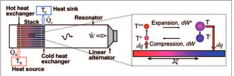
In Figure 1, the schematic of a standing wave ther-moacoustic engine is shown. A therther-moacoustic stack put between hot and cold heat exchangers (HHX and CHX) is placed in the resonator. The gas-filled reson-ator is connected to a linear alternreson-ator at one end and has a solid wall at the other. When a sufficient tem-perature difference is applied along the stack, an acoustic oscillation starts spontaneously. A standing wave is present in a quarter-wavelength mode with the pressure anti-node at the solid wall end. The acoustic power transmitted along the resonator can be extracted by the linear alternator to provide electrical power. The gas parcels within the channels between stack plates undergo a thermodynamic cycle as shown on the right of Figure 1.
The thermoacoustic effect was qualitatively explained by Lord Rayleigh in 18781: ‘‘If heat be given to the air at the moment of greatest condensa-tion, or be taken from it at the moment of greatest rarefaction, the vibration is encouraged’’. In 1960s, a quantitative theory was developed by Rott.2,3 In his works, wave and energy equations were derived for the sound of a single frequency propagating along a channel possessing a temperature gradient.
The thermoacoustic engines can be generally cate-gorized into two groups: standing-wave and travel-ling-wave, according to the phase difference between pressure and acoustic velocity oscillations. In the standing-wave engines,4,5 the thermoacoustic core is often placed in a quarter- or half-wavelength reson-ator. The term ‘‘core’’ denotes an assembly of the
stack sandwiched between HHX and CHX.
Imperfect heat transfer between the gas and the solid material is realized to produce a significant time delay between the movement of the gas and its expansion (or contraction) to meet Rayleigh’s criter-ion. Due to this imperfect heat transfer, the thermo-dynamic cycle in the standing-wave engines is intrinsically irreversible and as a result they typically have relatively low efficiencies.
Ceperley6,7 was the first to note the similarity between the thermodynamic cycle experienced by a gas parcel in a travelling-wave acoustic field and the Stirling cycle. The gas experiences expansion during the displacement toward the higher temperature and
contraction during the displacement toward the lower temperature, when the travelling wave propagates through the regenerator from its cold to hot end. Here, the solid material is referred to as a regenerator, following the convention in Stirling devices, to indi-cate that the thermal contact between the gas and the solid material is excellent. In this way, the correct time phasing is achieved to meet Rayleigh’s criterion, while efficiencies are significantly improved due to imple-mentation of a reversible thermodynamic cycle. However, acoustic power is required to be fed into the cold end of the regenerator to exercise the Stirling-like thermodynamic process. Hence, the ther-moacoustic core here resembles a power amplifier.
Thermoacoustic devices are thought to be particu-larly attractive due to the lack of moving mechanical components.4,8This provides a potential for high reli-ability and low maintenance. The working fluid is usu-ally a pressurized noble/inert gas, making this technology environmentally friendly. Furthermore, for the thermoacoustic engine to operate, the required temperature difference can be relatively small. For example, de Blok reported that the acoustic oscilla-tion starts at a temperature difference of only 65 K in the engine.9 Therefore the thermoacoustic engine technology shows a great potential for utilizing waste heat, typically of low grade, or other renewable energy sources, such as biomass combustion and con-centrated solar power.
[image:2.595.115.496.71.196.2]SCORE (Stove for Cooking, Refrigeration and Electricity supply) is a 2 M research consortium, aiming to develop a stove which would contain the functionality of micro-generation of electricity and some cooling capability for remote and rural communities in developing countries. Both func-tionalities are to be provided by the development of appropriate thermoacoustic technologies. The SCORE partners are University of Leicester, University of Nottingham, Queen Mary University of London, City University London and a charity Practical Action. By its work, SCORE aims to signifi-cantly improve health and quality of life in the rural communities by understanding their energy needs and working with them in order to develop their cap-abilities to manufacture an affordable versatile
domestic appliance. The target device is to combine the functionalities of a high-efficiency cooking stove, an electricity generator and a refrigerator (cool box), which would be fuelled by burning biomass products. It is also conceivable to consider other renewable energy sources such as concentrated solar irradiation. There is a clear need for developing the stoves described above: over 3.3 billion people live in rural areas; 2.4 billion people use biomass for cooking; about 2 billion people have no access to electricity, the great majority of them being rural people. The work is also going to ensure that in the long term the devices are acceptable at a technological, eco-nomic and social level and that there is a sufficient scope for the communities to develop numerous busi-nesses from the manufacture, repair and innovative applications of SCORE. Naturally, such a complex project needs to be broken down into smaller tasks including: (i) social science studies, and in particular identifying the energy needs of the communities con-cerned10,11; (ii) design of the stove12; (iii) development of the thermoacoustic electricity generator; and (iv) development of the thermoacoustic refrigeration tech-nologies. The final step will have to be the integration of various subsystems into one device.
Based on the social science research,10,11 the cur-rent cost of a device, capable of producing 25 W peak electrical power for a family dwelling, is around 500 USD (275 GBP) – this is typically based on applica-tion of thermoelectric devices. However it is also clear that an acceptable price level is actually an order of magnitude lower: 50 USD (27.5 GBP) for a 25 W device, and of course proportionally more for higher powers. Social science research also indicates that the power rating of an ideal system for a rural dwelling in a developing country should aim at peak electrical power levels between 50 and 150 W, while the price should ideally be below 100 USD. Generating these amounts of electricity as a by-product of cooking activities (essentially bio-mass burning) would there-fore be of immense benefit from the social perspective. This paper is intended to provide an overview of the research and development work undertaken ini-tially at the University of Manchester and subse-quently at the University of Leicester for the SCORE project. Firstly, the developments of a number of demonstrators of an electricity generator to deliver 10–20 W of electricity are described. Issues of concern such as the engine topology, the heat exchanger configurations and the use of commercial loudspeakers as linear alternators are discussed. Secondly, the development of a demonstrator of a travelling wave cooler coupled with an electrically driven standing wave engine is presented. Towards the end, the paper will summarise the achievements to date and outline future work.
It should be mentioned that while this paper will not focus explicitly on the cost analysis of the pro-posed devices, and neither are the demonstrators
built to a specific cost, many of the design choices are driven by a ‘‘low-cost’’ approach which ultimately should be beneficial in the resulting mass produced devices. Good examples here are the choice of air at atmospheric pressure as the working fluid (to elimin-ate the need for expensive gases, unavailable in rural areas, and to allow using PVC pipes for resonators), devising uncomplicated heat exchanger topologies (to simplify manufacturing operations and thus reduce cost) or using loudspeakers as linear alternators. It will be helpful to the reader to bear this ‘‘low-cost’’ philosophy in mind while looking at the technical implementations and scientific context.
Literature review
In the past decades, a variety of thermoacoustic engines have been devised to convert thermal energy to acoustic power using the thermoacoustic effect. Improvement of their thermal efficiency (i.e. from heat input to acoustic power output) remains one of the challenges. Swift4designed and tested a large scale standing-wave thermoacoustic engine. Pressurized helium was used as the working gas. The engine could deliver 630 W of acoustic power to the external acoustic load, converting heat into acoustic power at a thermal efficiency of 9%. Several other prototypes of standing-wave engines of different sizes or config-urations have been studied by various researchers. The highest thermal efficiency, being the ratio of the acoustic power leaving the thermoacoustic core over the heat input, is reported to be only 18%.5The ther-mal efficiency of standing-wave engines is understood to have an upper limit of around 20%,8 due to the already mentioned intrinsically irreversible thermo-dynamic cycle.
In order to overcome the efficiency limitations of standing-wave devices, travelling-wave devices became the focus of increased research interest. For instance, Sugita et al. used an electro-dynamic acous-tic source to test the travelling wave power amplifica-tion for cryo-cooler applicaamplifica-tions.13Gardner and Swift designed a cascade thermoacoustic engine,14 where one stage of a standing-wave thermoacoustic core is used to generate acoustic power to be fed into the adjacent travelling-wave stages for power amplifica-tion. Other various acoustic feedback mechanisms were used by Yazaki et al.,15 de Blok,9 and Backhaus and Swift.8,16
caused large viscous losses due to high acoustic velo-cities in the regenerator.
Subsequently, based on the concept of a compact acoustic network, Backhaus and Swift8,16 designed a new type of thermoacoustic engine, which utilises high acoustic impedance to suppress the high acoustic loss. The thermoacoustic core was placed within a torus of a length much shorter than the acoustic wavelength. A long standing-wave resonator was connected to this torus just after the secondary ambient heat exchanger. Their thermoacoustic Stirling heat engine demon-strated a much higher thermal efficiency of 30%, which corresponds to 41% of Carnot efficiency. Essentially, the torus of the engine is an acoustic ana-logue of the free-piston Stirling engine by using a compact acoustic network which included acoustic inertance, compliance and resistance. In addition, a thermal buffer tube (TBT) and a ‘‘jet pump’’ were utilized to suppress the Rayleigh streaming and Gedeon streaming which cause the parasitical heat losses.8 The long quarter-wavelength standing wave resonator was introduced to provide the acoustic res-onance to allow the torus to work at a relatively low frequency, compared with the one-wavelength mode of the torus. For the same type of engine, a new record of 49% of Carnot efficiency has been more recently set by Tijani and Spoelstra.17 A high tem-perature heat source was used at the engine hot heat exchanger (HHX), in order to produce a high tem-perature difference along the regenerator.
However, another separate and important chal-lenge in the engineering of thermoacoustic engines is to reduce the temperature gradients required for the engine excitation. This is motivated by the utilisation of low grade heat. de Blok9pointed out that, in the torus-type travelling-wave engine, the combination of the high regenerator impedance and the large acoustic loss in the standing-wave resonator make the onset temperature difference, required for the engine excita-tion, very high. Therefore, he proposed a hybrid configuration with a travelling-wave feedback wave-guide.9 The designed travelling-wave thermoacoustic engine with a feedback pipe (FBP) could start at a temperature difference of only 65 K. Recently, a multi-stage version of this type of engine was able to start at a temperature difference of only 40 K at each stage.18
The acoustic power generated by the thermoacous-tic engines from the heat input can be utilized in dif-ferent ways. In general, it can be used for two main purposes: one is to directly convert the acoustic power to electricity through an electro-dynamic transduction mechanism; the other is to drive coolers or heat pumps,5 which can be either thermoacoustic coolers (heat pumps) or pulsed-tube coolers.
Depending on the range of the acoustic impedance of electro-dynamic transducers, there may be different methods of coupling the transducers to the thermoa-coustic engines. Several thermoathermoa-coustic generator
prototypes have been built and tested. A compact travelling-wave thermoacoustic generator prototype has been developed for electricity generation aboard spacecraft by integrating the thermoacoustic engine with a linear alternator.19Instead of using an acoustic resonator for the control of resonance frequency, the moving mass of the linear alternator is used as a react-ive impedance to create a resonance with the compli-ant gas spring of the thermoacoustic Stirling engine volume. The device achieved a highest thermal to elec-tric conversion efficiency of 18%. Alternatively, the linear alternator can also be coupled simply as a load to the standing-wave acoustic resonator of the thermoacoustic engine. In this case, the acoustic res-onance remains to be provided by the acoustic reson-ator. A thermal to electric conversion efficiency of 15% was achieved in a recent work on this combin-ation,20 with the acoustic resonator dissipating an additional part of acoustic power. Other alternatives include integrating a piezoelectric generator with a thermoacoustic engine.21
In the aforementioned combinations of the thermo-acoustic engines with the linear alternators, the linear alternators usually have very high acoustic impedance (i.e. large force and small displacement) at the operat-ing frequency. They need to be installed at a high impedance region of the acoustic field in the thermo-acoustic engines for optimal operation. The high impedance generally leads to a high pressure drop across the piston of the linear alternator. In most linear alternators, a clearance seal is usually adopted to avoid friction losses.19Therefore, when the pressure difference between two sides of the piston is high, the clearance seal could lead to high seal losses due to the gas passing through the gap, which constitute a form of acoustic streaming. Such streaming will accumulate the gas on one side of the piston and, as a result, the unequal mean pressure at two sides of the piston will create an excessive piston drift.
With all of above effects taken into account, the combination of a looped-tube travelling wave engine with low acoustic impedance transducers clearly has been considered as a viable development route for the SCORE project. Based on this concept, several dem-onstrators of the thermoacoustic electricity generators were developed and tested, and the main milestones are reported here.
The thermoacoustic refrigerators (and heat pumps) have also been a subject of significant research interest in the past decades, since Hofler demonstrated a suc-cessful prototype of a thermoacoustic refrigerator (cooler) driven by a loudspeaker.22 Many thermoa-coustic refrigerators have been developed and stu-died.23–25 Specialised applications have also been investigated including gas liquefaction,26mixture sep-aration27or a freezer for ice cream storage.28Since the early implementations of thermoacoustic refrigerators showed a relatively low performance, various param-eters and components of the thermoacoustic refriger-ators have been investigated for further improvement. These included the system configuration,29 stack geometry,30,31 working fluid,32 the resonator,33 the electrical driver34 and other parameters.35 The best cooling performance of a refrigerator achieved appears to be 30% of a coefficient of performance (COP) relative to Carnot COP for a cooling power of 210 W at 233 K.36
Thermoacoustic refrigerators can be driven by an acoustic driver such as a loudspeaker or linear com-pressor. They can also be driven by a thermoacoustic engine as the source of acoustic power. The coupling of thermoacoustic engine to a thermoacoustic refrigerator or pulse tube cooler has been investigated previously. One of the main foci was to obtain either a high performance systems or very low temperatures. Considerable research effort has been put into both simulation and experiment of such arrangements.37,38 Devices of this type are capable of achieving the cryo-genic temperature range,39,40 down to about 2 K as reported by Wang et al.41
From a slightly different perspective, the complete system of a thermoacoustic engine driving the thermoacoustic refrigerator may be considered a ‘‘sus-tainable’’ system, if the heat source for the thermoa-coustic engine is waste heat42,43 or from renewable sources such as solar44 or geothermal energy. There is a huge need of a cooler for storing vital medical supplies for the rural communities of developing countries. Since the electricity supplies may generally not be available, the cooling system driven by heat from a stove or renewable sources is particularly attractive.
The concept of a coaxial travelling wave cooler was firstly proposed and developed by Tijani and Spoelstra.45In the current work, the coaxial travelling thermoacoustic cooler is adopted and coupled with a standing wave thermoacoustic engine, which converts low grade energy (from biomass burning in a stove,
here simulated by electrical input) into acoustic power, which is in turn used to produce the refriger-ation effect in the cooler. As already mentioned in the introduction, the design of such a target system has constraints on the capital cost, low maintenance and ease of repairs in the conditions where access to pre-cision manufacturing and servicing facilities may be limited, but these will not attract significant attention in this paper.
Thermoacoustic electricity generator
Currently, there are no linear alternators of low acoustic impedance readily available on the market. Therefore, in the current work, more conventional electro-magnetic transducers (i.e. easily available audio loudspeakers), were used as an approximation of the low impedance linear alternators. Their integra-tion within the looped-tube type thermoacoustic engines leads to new challenges and design consider-ations. Here, the concepts of coupling audio loudspeakers to a thermoacoustic engine are investi-gated in detail, both theoretically and experimentally; generation of useful amounts of electricity is demonstrated.Concept and simplified model
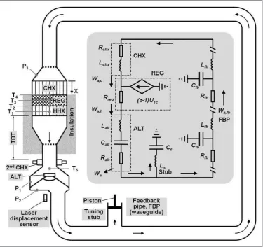
The main concept of the thermoacoustic electricity generator based on the looped-tube configuration46 is shown schematically in Figure 2. The thermoacous-tic core consists of a CHX, a regenerator (REG) and a HHX. The acoustic power generated is partly extracted by the alternator (ALT), with the remaining part being returned to the cold end of the regenerator through the FBP for amplification. A sufficient tem-perature gradient in the direction of acoustic propa-gation is crucial for the regenerator to operate as an acoustic power amplifier, as it increases the volumetric velocity in the regenerator. With the acoustic pressure nearly constant, the acoustic power is thus increased. The regenerator has a much larger cross sectional area Athan that of FBP, in order to improve the generator performance by having impedance ZMa/A,8 where M and a are mean gas density and speed of sound, respectively. Two tapered sections are required to minimize the flow separations introduced and the corresponding streaming and heat leaks.47 Flow straighteners can be installed to suppress streaming; these are indicated by dashed lines in Figure 2 and usually made of a few coarse mesh disks.
cancel the acoustic reflection introduced by the alter-nator, by adding an equal and opposite reflection. The stub length can be varied by moving a piston placed in the pipe to enable a degree of fine tuning. Its effect on the engine performance is discussed in Section ‘‘Effect of stub on impedance matching’’. After the stub, the long FBP connects back to the CHX.
According to the loudspeaker linear theory,48 to achieve high transduction efficiency, the alternator should have a high force factor Bl, low mechanical resistance Rm, and low electrical resistance Re. Furthermore, for a given frequency, the electrical power production capacity also depends on the excur-sion of the alternator; therefore, an alternator with a high excursion is preferred.
An equivalent lumped electrical circuit of the whole thermoacoustic electricity generator is also presented as an inset in Figure 2. This simplified model is very useful for understanding the behaviour of the system. However, the whole system is admit-tedly very complex by involving acoustic, mechanical and electrical components. Therefore, a more specia-lised modelling tool, referred to as Design Environment for Low-amplitude ThermoAcoustic Energy Conversion (DeltaEC), is employed for a quantitative analysis.49
Construction and evaluation of the developed
demonstrators
Over the project duration, several demonstrators were built and tested.46,50–52Each one had a different focus and has accordingly used different components or configurations to serve the purpose. In the following sections, the main features of each demonstrator are described and their performance, in terms of efficiency or power output, is presented and discussed.
[image:6.595.117.493.71.424.2]Demonstrator A. The first demonstrator was driven by an electrical heater in order to have a good control of heat input for testing the system performance.50,51 The overall layout is the same as shown in Figure 2. The main CHX is made out of a round aluminium block of 110 mm diameter and 90 mm length, as shown in Figure 3. Gas passages are made in the form of 45 holes of 5 mm diameter, parallel to the CHX centreline. Twelve holes of 6 mm diameter are made in perpendicular direction as passages for cooling water. The HHX is made in a similar way to the CHX, except that it is made out of brass to withstand much higher temperatures. It is 51 mm long and has 64 holes of 7 mm diameter parallel to the axis for gas passage. Nine ¼ inch holes are
prepared to hold nine cartridge heaters, each capable of providing 100 W of heat input. Thermocouples are embedded to monitor the temperature at various loca-tions. The regenerator is made out of stainless mesh screen disks with the mesh number 34 and the wire diameter 0.254 mm. It has 33 mm length and is con-tained in a stainless steel regenerator holder, sand-wiched between CHX and HHX.
Below the HHX there is a short section of a large diameter TBT, which is simply a section of stainless-steel pipe. The four parts described so far are clamped between two 4 inch flanges. To reduce heat losses, the regenerator, HHX and the short section of TBT are enclosed within a ceramic insulation material. The large diameter TBT is connected to a section of a smaller diameter TBT via a short transition cone, which reduces the diameter from 110 mm to 54 mm over a distance of 20 mm. A 2ndCHX is introduced to prevent the hot air reaching the alternator housing. The 2ndCHX is made out of a piece of car radiator that tightly fits inside the small-diameter buffer tube. A cooling water jacket surrounds the outside of the pipe at this position.
The alternator housing is installed about 50 mm below the 2ndCHX. A glass window is fitted in the bottom flange of the housing for a laser displacement sensor to measure the displacement of the alternator diaphragm. Pressure is measured before and after the alternator diaphragm. The FBP is made out of stand-ard 2 inch PVC pipes and 90elbows. The total length
of the loop is 4.03 m which determines the operating frequency at 75 Hz with air at atmospheric pressure as working medium.
It should be noted that the CHX has a very low porosity of 10%. The gas passages are in form of
5 mm holes of 90 mm length. As a result, the CHX produces a noticeable inertance effect in addition to the usual acoustic resistance.46This provides a phase change to help create the preferred condition for an efficient regenerator (i.e. U1 leads p1 at the cold end and U1 lags p1 at the hot end8). B&C 6PS38 loud-speaker is used as an alternator. Its specifications and the Thiele/Small parameters are summarized in Table 1. A high-power variable resistor is used as an electrical load for electrical power extraction. The alternator was installed after the TBT where the min-imum of acoustic impedance appears in the loop. At this location, a sufficient volumetric velocity can be obtained to drive the alternator to a high excursion which should subsequently maximize the electrical power output.
When the alternator terminals are open, acoustic oscillation starts when the hot end temperature of the regenerator (T1) reaches 240C, with the cold end of the regenerator T4 always at 30C.51 When a load resistor is connected, the temperature difference required for start up increases substantially. For instance, for a load resistance of 28.4, the acoustic oscillation starts when T1 reaches 261C. When the load resistance drops to zero (i.e. short circuit between the terminals), the onset temperature goes up to 530C.
Effects of heat input and load resistance on the generator performance were investigated.
51
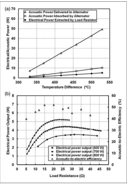
[image:7.595.54.276.68.275.2]The heat input was varied from 300 W to 800 W to change the temperature difference between the two ends of the regenerator (T1–T4), while the load resistance was fixed at 28.4. Generally, the acoustic power deliv-ered to the alternator and absorbed by the alternator, and the electrical power extracted by the load resistor all increase linearly with the temperature difference (T1–T4), as shown in Figure 4a. At the highest input power of 800 W, the temperature difference across the
Figure 3. Cold heat exchanger used in demonstrator A. Here the water and gas flow channels are simply drilled in an alu-minium block for ease of manufacture. Hot heat exchanger was made of brass due to higher temperatures used, but was con-ceptually of similar design.
Table 1. Specifications of the loudspeakers used as alternators.
B&C B&C B&C B&C 6PS386 6PS386 8BG51 8BG51 nominal measured nominal measured
Nominal diameter (mm) 170 – – –
Fs(Hz) 75 62 52 40.49
Bl(Tx/m) 10.8 9.6 11.8 11.09
Le(mH) 0.6 0.479 0.5 0.48
Re() 5.4 5.41 5.1 5.16
Qes 0.31 – – –
Qms 11.7 – – –
S(cm2) 132 – 220 –
Xmax(mm) 6 – 6.5 –
Mm(g) 14 17.0 35 27.4
Km(N/m) 2778 2621 3736 1773
[image:7.595.303.534.95.297.2]regenerator is 530C. The acoustic power produced that goes to the alternator is 49.3 W and the acoustic power absorbed by the alternator is 10.3 W. The load resistor extracts 5.17 W of electrical power. Here, the acoustic-to-electric efficiency,ZAE is 50%, the ther-mal-to-acoustic efficiency, the ratio of the absorbed acoustic power over the heat input,ZHA is 1.29%, and the thermal-to-electric efficiency, the ratio of the electrical power output to the heat input, ZHE is 0.65%.
Effects of load resistance on the electrical power output from the alternator and ZAE are shown in Figure 4b. The electrical power was measured at three heat input values. For a given heat input, there is an optimum load resistance that can extract a maximum electrical power. At the maximum heat input of 800 W, a maximum electrical power output of 5.17 W was obtained at the optimal load resistance of 23. For the heat input of 700 W, a maximum elec-trical power output of 4.44 W was obtained, at the load resistance of 26. The maximumZAE is 52% when the load resistance is around 20. The decrease inZAEat higher load resistances is considered to be related to the displacement of the loudspeaker
diaphragm. The experimental results show that the displacement of the diaphragm increases from 2.0 mm to 5.1 mm, when the load resistance changes from 5to 40. For this alternator, the maximum stroke is 6 mm (Table 1). The losses due to the non-linear effects would increase when the displacement approaches the maximum, and this may cause the reduction ofZAE.
Demonstrator B. While demonstrator A was useful in showing that small amounts of electricity (just above 5 W) can be generated, it was clear that there is a room for significant improvement. A weakness in the design proved to be the HHX. The brass block design was impractical – when clamped at elevated temperatures the HHX material deformed leading to problems with reliable seals. However on the thermal performance side it also proved unsatisfactory. The limited number of large diameter gas passages meant that not enough of thermal input from cart-ridge heaters was transferred to the working fluid, and this resulted in significant heat losses to the ambi-ent. The changes incorporated in demonstrator B (Figure 5a) mainly addressed the improvement of solid-gas heat transfer in the HHX: Firstly, in place of the brass block, a thin cable heater (3.17 mm diam-eter), 2.4 m long and rated at 1000 W was introduced. As shown in Figure 5b, it was wound into a spiral in two layers. Several coarse mesh disks were attached to enhance the heat transfer between the heater and working gas.
Further changes were introduced to the design of TBT, especially by changing the angle of contraction cone between large and small diameter TBT to reduce minor losses, but also by including the regenerator holder above the HHX as part of the TBT design (cf. Figure 5b). Further optimisation led to a shorter regenerator with 21 mm length. The stainless steel container, integrating functions of regenerator and HHX holder, and the TBT is surrounded by an insu-lation blanket (cf. Figure 5a). The total length of the loop is around 4.25 m which leads to an operating frequency of 69–70 Hz depending on the thermal con-dition.46 The device starts acoustic oscillation at a lower temperature difference of 120C. It can achieve
a thermal-to-electric efficiency, ZHE at 1.4% at its best, compared to 0.65% for demonstrator A. The maximum electrical power output is 11.6 W with a heat input of 900 W, the thermal-to-electric efficiency, ZHEbeing 1.3%. It is worth noting that the changes introduced more than doubled the electrical output (from 5.17 to 11.6 W).
[image:8.595.67.287.69.386.2]The dependence of the electrical power output on the applied heat input is shown in Figure 6. Measurement results are indicated by the symbols, and the solid line shows the simulation results from DeltaEC. Both indicate that the electric power output increases with the heat input. At low power level, the prediction is close to the measured values. The
calculation overestimates the electrical power output at high power level. This could be mainly due to the fact that the heat loss to the ambient is considerably higher at a higher temperature. It is considered that the underestimation of the electrical power output when the heating power is less than 500 W is related to overestimated acoustic losses.
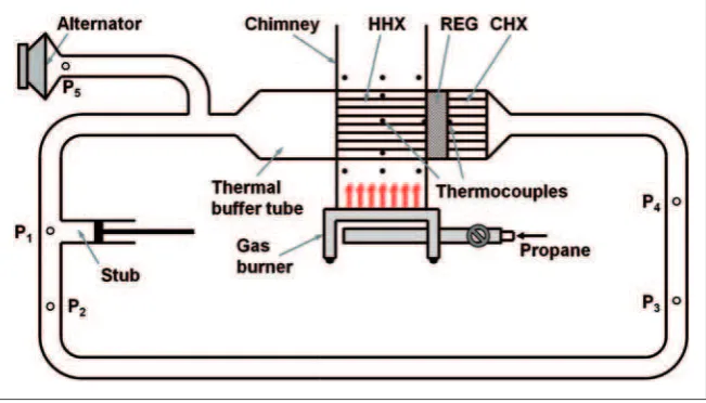
Demonstrator C. With a better understanding of the acoustic and thermodynamic behaviour of the combin-ation of a looped-tube type engine with an alternator of low acoustic impedance, further effort was made to move one step closer to converting heat from combus-tion into electricity, by developing demonstrator C, as shown in Figure 7. The HHX was designed in a shell-and-tube configuration with working gas oscillating inside 37 stainless steel tubes, with internal diameter of 8 mm and 160 mm in length. The HHX porosity is about 19.6%. The thermal input is supplied by a pro-pane gas burner with an adjustable heating power in
the range of 0–5 kW. The flue gas passes in between the tubes located in a chimney duct. The configuration of HHX has been chosen as a compromise between per-formance and ease of manufacture: welding a bundle of tubes should be easy to repeat in ‘‘blacksmithing’’ workshops in remote rural areas.
The space between the flange and the front face of the channels (cf. Figure 8) of the HHX accommodates the regenerator. It is 23 mm long and made from 72 stainless mesh screen disks. The same CHX is used as in previous demonstrators, albeit a wider angle cone was used to connect it to the PVC pipe in order to reduce minor losses. The TBT is part of the HHX design, in the form of a simple pipe extension at the back of the HHX. It is connected to a smaller diam-eter TBT via a short transition cone. A 2ndCHX is attached to the end of the TBT to remove residual heat. About 700 mm away from it, an acoustic stub is connected to the resonator to match the impedance between the alternator and the engine. The system performance was investigated with the alternator located at one of the pressure amplitude maxima, which is 965 mm away from the T-junction of the stub (Figure 7). This arrangement was designed to keep the influence of the alternator on the acoustic field in the engine to the minimum.52 The total length of the loop is around 4.1 m, and the operating frequency is around 70 Hz.
When the alternator is not present, the acoustic oscillation starts when the temperature difference between two ends of the regenerator reaches 107C.
With the alternator installed and without any load resistance, a minimum onset temperature difference is 134C. At the highest heat input, the solid
tempera-ture of the HHX reaches 510C. The temperatures at
the two ends of the regenerator are 403C and 112C,
respectively. Electrical power of 8 W was extracted through the electrical resistor of 15.8, as indicated in Figure 9.
[image:9.595.102.480.72.245.2]The electrical power output increases almost lin-early with the temperature difference between the
Figure 5. Photograph of the thermoacoustic electricity generator demonstrator B (a); and HHX assembly (b).
[image:9.595.54.277.296.477.2]two ends of the regenerator. To protect the welding joints within the HHX, the solid temperature was limited to 500C, which meant that the temperature difference between two ends of the regenerator can only reach around 290C.52
By a reasonable extrapo-lation, it would be possible to obtain around 15 W of electrical power if the temperature difference could be increased to 400C by exceeding the imposed solid
temperature of 500C.
The acoustic-to-electric efficiency is around 35% according to the measured acoustic power with the two-microphone method.53 In this configuration, the input heat from the gas burner and the net heat input to the engine were not measured. Thus, the overall ther-mal-to-electric efficiency is not available. A DeltaEC simulation was carried out to produce the pressure amplitude and the acoustic power flow along the loop, which are in good agreement with the measure-ments. According to the simulation, ZAE¼53%,
ZHA¼4.6% and, ZHE¼2.4% However, ZAE
from measurement is considerably less than that from the simulation. This is thought to be linked to the acoustic losses that are caused by the sharp transi-tions between the FBP and alternator housing, which were not included in the DeltaEC simulations.
Demonstrator D. One particular issue with demonstra-tor C was the limited temperature difference between the two ends of the regenerator, which prevents the engine from producing more acoustic power. It is con-strained by the solid temperature of HHX (self-imposed experimental limit of around 500C) and a
high cold end temperature of the regenerator, which could reach 112C. The latter is mainly caused by the
design of the CHX, used in previous demonstrators, which does not have sufficient heat transfer area. Therefore, a first major change in demonstrator D was a new CHX, designed based on DeltaEC simula-tions. It is made out of an aluminium block with length of 60 mm. Gas passages are made in the form of 430 holes with the diameter of 3 mm, parallel to the CHX centreline, giving the porosity of about 32%. Passages for cooling water are made perpendicular to the CHX’s centreline in a similar way as in the previous design. The regenerator, HHX, TBT and other parts of dem-onstrator C remain practically unchanged.
[image:10.595.71.535.71.206.2]A second major change was in the configuration and type of the alternator used. It is connected through a 920 mm long pipe to the end of the TBT via a stainless steel T-junction (cf. Figure 10). Part of the acoustic power passing by the T-junction is extracted by the alternator; the remaining acoustic
Figure 7. Schematic (a) and a photograph (b) of the thermoacoustic electricity generator demonstrator (C).
[image:10.595.64.289.248.422.2]Figure 8. Front view of the shell-and-tube hot heat exchanger.
[image:10.595.320.544.249.420.2]power is transferred back to the thermoacoustic core along the FBP. Also, a different loudspeaker (B&C 8BG51) was utilized as the alternator for its relatively high transduction efficiency and low acoustic imped-ance (cf. Table 1). As in previous demonstrators, an impedance matching stub is adopted; the overall length of the loop is around 5.04 m, and the operating frequency is around 64 Hz.
A third major development compared to demon-strator C was that some quantitative measurements of heat input to the HHX were possible by enclosing the gas burner in a purpose built housing. The heat input to the HHX is worked out by measuring the inlet and outlet temperatures of the flue gas and its flow rate. The influence on the generation of electrical power due to the presence of the housing was also investi-gated by testing the demonstrator with and without the gas burner enclosed in the housing, as illustrated in Figure 11.
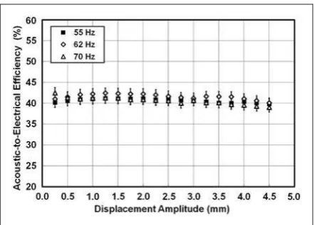
The demonstrator can produce 17.8 W of electrical power when the temperature difference across the regenerator reaches 340 K. When the gas burner is enclosed in the housing, the electrical power output is reduced. This is most likely related to different heat transfer characteristics of the HHX under two test con-ditions. Compressed air supply was used in the housing to force the flue gas through the tube bundle of the HHX, while the flue gas was driven by buoyancy only when the gas burner was not put in the housing. The resulting heat transfer and temperature distribu-tion within the HHX would inevitably differ. The ther-mal-to-acoustic efficiency for this demonstrator is estimated to be around 33.5%, when the tempera-ture difference was between 300 and 340 K. The effi-ciency decreases as the heat input decreases. The acoustic-to-electric efficiency decreases from 60 to 50%, as the displacement amplitude of the loudspeaker diaphragm increases. As a result, the thermal-to-elec-tric efficiency was in a range of 1.5 to 2% for most of the test cases. The electrical power output of the
demonstrator calculated from the DeltaEC model agrees well with the measurements when the gas burner is not included in the housing, as indicated by Figure 11. The discrepancy between the prediction and the measurement increases at smaller temperature dif-ference across the regenerator. This is thought to be related to the temperature difference across the regen-erator. Temperature measurements at a single point at the hot end of the regenerator were used to represent the mean temperatures in its cross section. The tem-perature in the cross section of the regenerator could be overestimated whenTis small and the gas burner is not in the housing.
Characterization of audio loudspeakers
as alternators
[image:11.595.129.455.73.259.2]In principle, there are several commercially available transduction devices that can be used to convert acous-tic to electrical power. These include commercial high impedance linear alternators (e.g. Q-drive type), piezo-electric transducers and the already mentioned audio
[image:11.595.308.529.305.466.2]Figure 10. Schematic of the thermoacoustic generator demonstrator D.
loudspeakers. The commercial high-impedance linear alternators often require precision manufacturing, while the piezoelectric transducers are very inefficient, and therefore these are not considered here. However, the ordinary audio loudspeakers are potentially good candidates for transduction devices used in SCORE, for two reasons. Firstly, they do not require precision manufacturing. Secondly, they can still achieve com-parable power transduction efficiencies. However, they also have disadvantages such as a fragile paper cone and a limited stroke. Therefore, they are not suitable for high power applications, with a high pressure dif-ference across the diaphragm. However, they may be suitable for relatively low power applications discussed in this paper, where the pressure difference across the diaphragm is usually in kPa range.
A simple linear model54of the loudspeaker that is used as a transduction device is developed and sche-matically shown in Figure 12. A pressure difference, pis applied on the loudspeaker diaphragm that has an effective areaS, caused by the acoustic wave. The volumetric velocity due to the diaphragm displace-ment isU1. The diaphragm and the coil, with a total mass, Mm, are subject to an oscillatory motion. The loudspeaker has a mechanical stiffness, Km, and a mechanical resistance, Rm. The coil has an electrical inductance, Le, and a electrical resistance, Re. The force factor is Bl. A pure electrical resistance, RL is connected as a load to extract electrical power in this model. The voltage on the load resistor isVL, and the current isI1.
In addition to the power extracted by the electrical load, part of the acoustic power absorbed by the loud-speaker is also dissipated by the mechanical resistance and the electrical resistance of the coil. For a loud-speaker, the electrical inductance of the coil is usually very small and can often be neglected. In order to extract the maximum electrical power by the load, its resistance, RL should be equal to the electrical resistance of the coil,Re. Maximum acoustic-to-elec-trical transduction efficiency is reached when the load resistance,RLis equal to Re
ffiffiffiffiffiffiffiffiffiffiffiffiffiffiffiffiffiffiffiffiffiffiffiffiffiffiffiffiffiffiffiffiffiffi
1þ ðBLÞ2=R
mRe q
.
For a given candidate loudspeaker, its characteris-tics can be measured and investigated. Figure 13 shows the relationship between the measured
[image:12.595.74.538.73.201.2]acoustic-to-electrical efficiency and the displacement of the diaphragm at three frequencies. The load resist-ance was fixed at 5.57, close to the coil resistance. The displacement amplitude was investigated in a range between 0.25 and 4.5 mm. It can be seen that the displacement amplitude does not affect the con-version efficiency significantly within the tested range. The efficiency increases and then decreases a little when the displacement amplitude increases from 0.25 to 4.5 mm. This implies that audio loudspeakers could be good candidates for alternators, when a high-displacement amplitude is required and a low-pressure drop is acceptable. The influence of load resistance on the acoustic-to-electrical efficiency was also studied with the displacement amplitude kept constant.54It is confirmed that an optimal load resist-ance exists, which leads to a high transduction effi-ciency. For the loudspeaker B&C 6PS38, an acoustic-to-electrical transduction efficiency of around 60% can be achieved. At the maximum power point, the transduction efficiency can still achieve 40%, as shown by Figure 13. Therefore, it is certainly practical to utilise the commercially avail-able loudspeakers as alternators for such applications.
Figure 12. Schematic of the physics model of the loudspeaker (a) and its equivalent impedance circuit (b).
[image:12.595.321.542.248.406.2]Effect of stub on impedance matching
In the current combination of a low-impedance alter-nator with the thermoacoustic engine, the alteralter-nator introduces an acoustic load to the thermoacoustic engine, which inevitably alters the acoustic field. An acoustically unmatched load generates an acoustic reflection and a high-standing wave ratio in the acous-tic FBP and thus causes large acousacous-tic losses. To extract the acoustic power in an efficient manner through the alternator and reduce the acoustic losses within the FBP, the load (alternator) has to match with the engine’s acoustic network. This is achieved by applying a technique of ‘‘stub-matching’’, very similar to that routinely used in microwave electronic circuits. In practice, an acoustic stub is introduced and attached to the wave guide at a location close to the load. The characteristics of the matching stub and its effect on the acoustic field were carefully stu-died with demonstrator B.46
The pressure amplitude distribution along the 4.25 m long looped tube in demonstrator B is shown in Figure 14a. There are two maxima and two minima of pressure amplitude along the loop and two sharp pressure drops. One pressure drop is along the regen-erator and the other at the alternator. Looking back to the simplified model as shown in Figure 2, the first pressure drop is caused by the flow resistance of the regenerator Rreg, while the second is caused by the acoustic resistance of the alternator,Ralt. The stand-ing wave ratio within the loop can be estimated by the ratio of the maximum over minimum pressure
amplitude which is relatively small (about 2.1). The acoustic stub does not cause a change in pressure amplitude, while it changes the slope at which pressure amplitude increases.
The distribution of volumetric velocity along the loop is shown in Figure 14b. There are also two maxima and two minima along the loop. One max-imum is in between the alternator and the stub, and the other near the end of the FBP where the minimum of the pressure amplitude is located. One minimum of the volumetric velocity is at the cold end of the regen-erator, while the other is close to the middle of the FBP. At the location of the stub, there is a sudden decrease of the volumetric velocity, for the reason that the stub shunts part of the volumetric velocity away from the resonator.
[image:13.595.130.456.71.345.2]Figure 14c shows the acoustic impedance along the loop. The acoustic impedance is highest at the cold end of the regenerator (Z5Ma/A). The impedance drops quickly because the pressure amplitude decreases while the volumetric velocity increases shar-ply from the cold to the hot end of the regenerator. The alternator causes a sudden drop of acoustic impedance due to the fact that the volumetric veloci-ties at two sides of the alternator are the same, while the pressure amplitude drops significantly due to the power extraction. The stub essentially works as a Helmholtz resonator. It introduces a sudden increase of the acoustic impedance along the loop, by keeping the pressure amplitude constant and shunting part of the volumetric velocity. It is very clear that the stub cancels out (almost perfectly) the acoustic impedance
drop caused by the alternator. For an optimised per-formance, the stub should be close to the acoustic loads, which are the alternator and the acoustic resist-ance of the FBP in this case. After a careful simula-tion process, it has been located about 330 mm away from the alternator. From Figure 14c, it can also be found that 0.6Ma/A<Z<1.6Ma/Aalong the FBP. Therefore, the dissipation in the FBP has also been minimized.
The phase difference between pressure and velocity oscillation along the pipe is illustrated in Figure 14d. The regenerator is at a near travelling-wave location. The phase angle decreases rapidly after the alternator. The stub introduces a sharp increase of phase angle to counteract this sharp phase angle decrease.
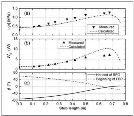
The influence of the matching stub on the electrical power output can be seen more clearly from Figure 15. A comparison is made between the simu-lation and experiments when lstub varies and RL is fixed at 15.6. In general, the measured p across the alternator has a good agreement with the
simulations. As lstub increases, p increases signifi-cantly. In the experiments, as the stub length increases from 0 to 0.68 m, the extracted electric power We increases about ten-fold, which agrees with the simu-lation qualitatively (Figure 15b). Without the stub (lstub¼0 m), the phage angle is 71 and 61 at the hot end of the regenerator and the beginning of FBP, respectively, while it approaches 0 when lstub&0.65 m (Figure 15c). The design strategy is to achieve the near travelling-wave condition around the regenerator and within the FBP, so that the acoustic power production within the regenerator can be max-imized, and the acoustic dissipation within the feed-back loop is minimized. It is shown that the acoustic stub can effectively tune the phase to the preferred condition. This also explains the strong dependence of Weon lstub. The function of the acoustic stub has been frequently validated through the tests on the demonstrators being developed.
Thermoacoustic refrigerator
[image:14.595.64.288.364.558.2] [image:14.595.140.469.655.755.2]Another important task of the project was the devel-opment of a thermoacoustic refrigerator. The object-ive of this task was to develop a demonstrator of a cooler for storing vital medical supplies for the rural communities of developing countries. Because the electricity supplies may generally not be available, it is thought that such a system could be driven by a thermoacoustic engine (powered by burning biomass) which delivers acoustic power to be utilized by a ther-moacoustic refrigerator. In the current work, a stand-ing wave thermoacoustic engine is chosen to convert the low grade heat from biomass burning in a stove, into acoustic power. The engine is coupled to a travel-ling wave thermoacoustic cooler, as shown in Figure 16. The cooler concept is similar to that devel-oped by Tijani and Spoelstra,45namely a coaxial tra-velling wave configuration is adopted. Air at relatively low pressure of 10 bar is used as working medium. The linear configuration of Standing Wave engine (SWE) and Travelling Wave Cooler (TWC) would be beneficial for the ease of construction. From the literature discussed in section ‘‘Literature review’’, it is understood that there is generally lack of widely accepted ‘‘optimal’’ geometries for such SWEþTWC
Figure 16. Schematic of the standing wave engine coupled with the travelling wave cooler.
couplings. This is because the optimal geometry strongly depends on the particular design targets and operating conditions and differs from case to case.
The main parts of the standing wave engine include: a stack, two heat exchangers and a resonator; their configurations are listed in Table 2. Electrical heating with Ni-Cr resistance heating wire was used within the HHX to provide heat input to the engine in order to simulate the biomass combustion at the cur-rent stage. The travelling wave cooler employs an acoustic network based on the same principle as the torus-shaped design45 to create the travelling wave phasing necessary to operate the thermoacoustic Stirling cycle and help to create a high-acoustic impedance in the regenerator. The acoustic power produced by the engine is delivered to the cooler, where the acoustic waves move from the ambient side to the cold side through the regenerator in order to pump heat from the cold to the ambient side. The ambient heat exchanger is fixed at 288 K, which is the temperature of cooling water. A cooling temperature of 250 K at the CHX of the cooler was the design target.
In the design optimization of the travelling wave cooler, the configuration of the standing wave engine is fixed, as presented in Table 2. The design of the travelling wave cooler and its performance analysis were aided by DeltaEC. The optimization procedure was performed by varying the values of the param-eters in each component, including the length and hydraulic radius of the regenerator, cooler diameter, length of the TBT and heat exchangers, and the com-pliance volume. The optimization process stops when the optimal configuration of the travelling wave cooler is achieved giving the maximum cooling per-formance indicated by the coefficient of perper-formance
(COP). The COP is defined as the ratio of the heat load of the cooler, Qc and the acoustic power deliv-ered to the cooler,Wacas follows
COP¼ Q_C
_
WAC
The acoustic power delivered to the cooler is taken at a position just before the co-axial cooler from the output of the simulation.
[image:15.595.307.532.280.481.2]As an example, the effects of the hydraulic radius and the regenerator length of the cooler on COP are illustrated in Figure 17. The ratio of hydraulic radius, rhto thermal penetration depth,is generally used in considering the regenerator geometry.55 It can be
Table 2. Specification of physical components of the standing wave engine and the travelling wave cooler.
Part name Dimensions Other specifications
The standing wave engine
Bounce space 211.58 mm ID, length 0.175 m
Hot heat exchanger 40 mm length with same area as the stack (given below) Resistance heating wire
Stack Length 0.2 m Parallel plate configuration of stainless steel
Area 1.95102m2
Plate spacing 0.5 mm Plate thickness 0.2 mm Porosity 0.576
Cold heat exchanger 44 mm length with the same area as the stack Water-cooled fin and tube heat exchanger
The travelling wave cooler
Flow straightener 120 mm ID, length 0.75 mm Stainless steel screens, mesh #20
Thermal buffer tube 120 mm ID, length 332 mm Thin wall stainless steel pipe
Wall thickness 1 mm
Cold heat exchanger 3.175 mm long with the same area as the regenerator Coiled cable heater
Regenerator 110 mm ID, length 30 mm,rh¼3.7105m Stainless steel screens, mesh #160
[image:15.595.54.529.563.775.2]Ambient heat exchanger 20 mm long with 8.17103m2heat exchanger area Fin and tube heat exchanger, mainly made of copper
regarded as an indicator of the effectiveness of ther-mal contact between gas and solid. If rh/ is low, a perfect thermal contact between working fluid and solid wall can be realized. However, this could increase the pressure drop across the regenerator con-siderably, which then results in low volume flow rate and causes low acoustic power transmitted to produce enough thermoacoustic refrigeration effect. The regenerator length has similar effects on COP. Generally speaking, a shorter regenerator causes smaller resistance to the flow, hence less consumption of useful acoustic power. However, the temperature difference created between the two ends of the regen-erator is limited. If the regenregen-erator is too long, the losses are much greater so that the cooling
performance deteriorates dramatically. Therefore, under these circumstances, the optimum regenerator length to utilize the acoustic power is obtained. The maximum COP obtained is approximately 2.06 atrh/ ¼0.34 and the regenerator length of 24.4 mm.
To compare the effects of individual parameters on the cooling performance, the dimensionless geometry ratio is introduced through normalisation by its opti-mal value as shown in Figure 18. The optiopti-mal geom-etry ratio equals unity at the maximum COP. Thus, this represents the sensitivity of COP to each param-eter of the cooler. As can be seen, COP is extremely sensitive to the cross sectional area ratio of the FBP to resonator and the hydraulic radius of the regenerator, while much less sensitive to the length of the TBT. This implies that the cross section area of the regen-erator and feedback/inertance tube, and the hydraulic radius of the regenerator are the vital parameters in the simulations of the coaxial thermoacoustic cooler driven by the thermoacoustic engine. At the optimal condition, the maximum achieved cooling load is 133 W at COP of 2.06.
[image:16.595.65.287.282.433.2]According to the guidance given by the optimiza-tion procedure, as shown in Table 2, the standing wave engine and the travelling wave cooler have been constructed; selected photographs of the whole assembly and the individual components are shown in Figure 19. The operating frequency of the combined system is 46 Hz.
Sample experimental data from the cooler tests are presented in Figure 20. Figure 20a shows the evolu-tion of the temperature of the cold end of the regen-erator with time when 2.5 kW of thermal input is
[image:16.595.116.491.498.745.2]Figure 19. Practical implementation of the TWC driven by the SWE: overall view (a), the hot heat exchanger in SWE (b), parallel plate stack in the SWE (c) and the coaxial TWC cooler (d).
applied to the SWE (here 2.5 kW of heat input pro-duces drive ratio of 3.25%). It can be seen that the temperature of around 18C is obtained after
30 min and around 20C after over an hour from
the start of the test. Figure 20b shows the dependence of the minimum temperature obtained at the cold end of the regenerator as a function of drive ratio (obtained drive ratio values correspond to the heat input to the SWE). Finally Figure 20c shows the cool-ing performance in terms of COP against the applied cooling load for different values of drive ratio (i.e. heat input to the SWE). In the current study the cool-ing load is imposed by resistive heatcool-ing. The acoustic power is calculated using the two-microphone method;53cf. sensors P1and P2in Figure 16.
Current and future work
The development of and the relevant experiments car-ried out on several demonstrators described in previ-ous sections illustrate the feasibility of developing electricity generators and refrigerators for rural com-munities based on the thermoacoustic technologies. However, there are several further steps that need to be taken in order to deliver systems that are relevant from the point of view of requirements of developing countries. Firstly, the electricity generator needs to be scaled up to deliver electric power in the range
of 100 W. In order to achieve this, a few challenges need to be addressed, including the application of a loudspeaker of a higher power rating, scaling-up the rig in the dimensional sense and adopting a concept of a two-stage engine design in order to better utilize the waste heat produced from cooking activities. Secondly, the target system should ideally include the functions of electricity generation and refriger-ation in a single device (to operate simultaneously or in alternate fashion).
Electricity generator based on two-stage
thermoacoustic engine
[image:17.595.62.522.434.753.2]As discussed previously, a looped tube travelling wave engine is relatively simple and easy to construct. It can also provide the travelling wave condition, where the alternator does not experience a high pressure differ-ence across the diaphragm or piston. However, the electrical power output from the single stage thermo-acoustic generator equipped with the second loud-speaker shown in Table 1 is limited to only about 18 W. In view of the limited length of the feedback loop (limited mainly by the resonance frequency of the loudspeakers) and the need to utilise a higher per-centage of waste heat for a more efficient heat recov-ery process, one would ideally like to introduce a second stage of the engine. With this in mind, a
two-stage thermoacoustic engine has been designed and is being developed and tested in order to achieve a higher electrical output.56This arrangement has also the advantage of utilising low-grade heat source with a lower temperature difference across each stage.9,18 The prototype uses air at two bar as the working gas and a commercially available high power woofer as an alternator. A schematic drawing of the prototype is shown in Figure 21a.
In the model, each stage consists of a regenerator made of stacked mesh screen discs, sandwiched between a parallel plate CHX and a shell-and-tube HHX, a TBT and a 2ndCHX. The two stages are con-nected through a FBP, with the alternator installed in between. The matching stub is connected to the looped engine in order to compensate the change of acoustic impedance due to the introduction of the alternator.
In an optimization process of the generator (similar to that undertaken for the thermoacoustic cooler pre-sented in Section ‘‘Thermoacoustic refrigerator’’), the effects of the porosity and length of HHXs, the length of regenerators, diameter of the FBP, and stub length have been investigated in order to find the optimal configuration. The objective was to achieve the highest electrical power output. The dimensions of CHXs/ 2ndCHXs are taken from the specifications of the com-mercially available car heater matrices. Heating power of 1 kW is applied at the HHX of each stage, although this may be an idealisation as the heat supplied to each of the two stages may not be equal. The stroke of the loudspeaker diaphragm is set to 8 mm, due to the lim-ited excursion and a load resistance of 15V is con-nected to the coil. The solid temperatures TS of CHXs are set at the ambient temperature of 297 K.
The final model obtained after the optimization procedure gives a prototype operating at 96 Hz. The required heat input at two stages is 2136 W. Within the first and second stages, 159 W and 140 W of acous-tic power are produced, respectively. The alternator extracts 210 W of acoustic power to produce 130 W of electricity. The calculated thermal-to-acoustic,
acoustic-to-electric, and thermal-to-electric efficiencies are 10%, 62% and 6%, respectively. The main par-ameters of the prototype are summarized in Table 3. Based on this, a demonstrator has been constructed, as shown in Figure 21b. Preliminary tests and debug-ging of the engine are currently underway and hence the prototype shown does not yet include all the envi-saged components.
Thermoacoustic device combining electricity
generator and cooler functionalities
[image:18.595.75.538.72.232.2]Another activity currently undertaken is the demon-stration of the device which would enable combining the functionalities of an electricity generator and cooler in one configuration. Clearly, this was one of the original objectives of the SCORE project. One
Figure 21. Schematic (a) and early prototype (b) of the stage thermoacoustic electricity generator.
Table 3. Main parameters of the two stage thermoacoustic electricity generator.
Parameter Value
Working frequency (Hz) 96
Working gas Air
Mean pressure (bar) 2
Drive ratio/pressure amplitude (%) 6.1 Hot heat exchanger Length (mm) 0.105
Porosity 0.4288
Plate spacing (mm) 8 Heat input (W) 2136 Solid temperature (K) 820
Regenerator Length (mm) 30
Porosity 0.82
Ambient heat exchanger Length (mm) 49
Porosity 0.62
Size (mm2) 235129 Thermal buffer tube length (mm) 60
Stub length (mm) 820
[image:18.595.315.547.310.557.2]of the simplest routes to obtaining such a device is to provide the alternative acoustic networks for an engine/generator and engine/cooler configuration enabled by opening/closing the flap/gate valves placed in the suitable places of the network. Figure 22 illustrates such configuration: by diverting the acoustic energy to the bypass duct by appropriate setting of flap valves 1 and 2 and opening the gate valve 3 to expose the alternator to the circulating acoustic power in the loop one could use the device as the electricity generator. On the other hand, by switching valves 1 and 2 to the position diverting the acoustic power flow through the cooler and shut-ting off gate valve 3, one could operate the device as a cooler. Clearly the lengths of the loop and bypass branch need to be selected in such a way that they correspond to the operating frequencies of the engine or cooler (they may not be the same). Similarly the tuning stub position may not be the same for the two alternative uses and may need to be adjusted appropriately.
Closing remarks
This paper gives a technical overview of the research and development activities undertaken under SCORE project at the University of Leicester. Firstly, the pro-cess of developing a working prototype of the com-bustion-driven thermoacoustic electricity generator capable of achieving 18 W of electrical power output has been shown by illustrating the consecutive proto-typing stages. The work described had to address many design issues including a suitable thermoacous-tic engine topology and control measures; design of suitable heat exchanger configurations; and character-isation of commercial loudspeakers for incorporation in the systems under test as linear alternators.
Secondly, the presented work included a demonstra-tor of a thermoacoustic cooler for sdemonstra-torage of vital medical supplies in remote and rural areas where there is no access to grid electricity. This has been driven by electrical heat input, but given the success of the combustion driven electricity generator it is only a matter of time to develop suitable heat exchan-gers for heat input from combustion processes. Further work is underway and this includes a two-stage engine to be used as an electricity generator cap-able of delivering around 100 W of electrical power and a combination of a cooler/generator functional-ities to fulfil the main objectives of the SCORE project.
Funding
Artur J Jaworski would like to acknowledge the support for his thermoacoustics research group received from EPSRC under grants EP/E044379/1 and EP/E044379/2.
Acknowledgments
Both authors would like to acknowledge Mrs Patcharin Saechan and Mr Kalid Abdoulla (both are PhD students in the Thermoacoustic Technologies Group at the University of Leicester) for help with creating some of the illustrative material, while Dr ZB Yu is acknowledged for collecting data used in Figure 11. Dr HF Kang is gratefully acknowledged for developing the DeltaEC model of dem-onstrator D and subsequent generation of modelling data presented in Figure 11.
References
1. Rayleigh L. The explanation of certain acoustical phe-nomena.Nature1878; 18: 319–321.
2. Rott N. Damped and thermally driven acoustic oscilla-tions in wide and narrow tubes. Z Angew Math Phys
[image:19.595.127.456.71.285.2]1969; 20: 230–243.