University of Southern Queensland
Faculty of Health, Engineering & Sciences
Regulating Rescue Package Descent through Controlled
Autorotation
A dissertation submitted by
Ian Michael Saxby
in fulfilment of the requirements of
ENG4112 Research Project
towards the degree of
Bachelor of Computer Systems Engineering
Abstract
This dissertation documents the design, implemention and test of a rescue package that is intended to be carried and released by a Remotely Piloted Aircraft System (RPAS) from a height of at least 65m. Current commercial designs for controlled air-drop deliv-eries include automated parafoil devices. The rescue package physical size is sufficient to contain a commercial 500ml water bottle. When released from the RPAS, the rescue package utilises the helicopter autorotation technique to control a safe descent and land-ing to a nominated ground point minimisland-ing package damage so that a human can use all the water. The design process considers System Safety from both hardware and software perspectives.
University of Southern Queensland
Faculty of Health, Engineering & Sciences
ENG4111/2 Research Project
Limitations of Use
The Council of the University of Southern Queensland, its Faculty of Health, Engineering & Sciences, and the staff of the University of Southern Queensland, do not accept any responsibility for the truth, accuracy or completeness of material contained within or associated with this dissertation.
Persons using all or any part of this material do so at their own risk, and not at the risk of the Council of the University of Southern Queensland, its Faculty of Health, Engineering & Sciences or the staff of the University of Southern Queensland.
This dissertation reports an educational exercise and has no purpose or validity beyond this exercise. The sole purpose of the course pair entitled “Research Project” is to con-tribute to the overall education within the student’s chosen degree program. This doc-ument, the associated hardware, software, drawings, and other material set out in the associated appendices should not be used for any other purpose: if they are so used, it is entirely at the risk of the user.
Dean
Certification of Dissertation
I certify that the ideas, designs and experimental work, results, analyses and conclusions set out in this dissertation are entirely my own effort, except where otherwise indicated and acknowledged.
I further certify that the work is original and has not been previously submitted for assessment in any other course or institution, except where specifically stated.
Acknowledgments
Mark Phythian, my supervisor, for his continued patience and understanding as I pro-gressed through this project. Don Luke, Bryan Walker, Harry Melnik and Keith Smith whom have been instrumental in translating my hardware ideas and sketches into proto-type fabrication. To my wonderful parents who have inspired in me the commitment and desire to achieve the best . To my beautiful Susanne and my cherished children Michael, Elizabeth and Andrew for their constant support and encouragement.
Contents
Abstract i
Acknowledgments iv
List of Figures xii
List of Tables xv
Nomenclature xvi
Chapter 1 Introduction 1
1.1 Motivation . . . 1
1.2 Aim . . . 2
1.3 Objectives . . . 2
1.4 Context . . . 2
1.5 Ethics and Implications . . . 4
1.5.1 Engineering Ethics . . . 4
1.5.2 Prototype Readiness Implications . . . 4
CONTENTS vii
Chapter 2 Previous Work 5
2.1 Chapter Overview . . . 5
2.2 Previous Work . . . 5
2.2.1 Navigation . . . 5
2.2.2 Transfer Alignment . . . 8
2.2.3 Australian Aerospace Regulatory Regime . . . 9
Chapter 3 Establishing System Requirements 11 3.1 Chapter Overview . . . 11
3.2 Concept of Operations . . . 11
3.3 System Safety Analysis . . . 12
3.4 System Safety Requirements . . . 14
3.5 System Requirements . . . 17
3.6 Chapter Summary . . . 18
Chapter 4 Rotary Deceleration System - Design and Construction 19 4.1 Chapter Overview . . . 19
4.2 Physical Design . . . 19
4.3 Electronics Design . . . 23
4.3.1 System Architecture . . . 23
4.3.2 Processor Selection . . . 26
CONTENTS viii
4.3.4 Pro mini Connector and Quadrature Encoder Sensor boards . . . . 28
4.4 Software . . . 30
4.4.1 Interface Design . . . 30
4.4.2 Software Design . . . 32
4.4.3 Software Operation . . . 34
4.5 Critical Design Analysis . . . 37
4.6 Chapter Summary . . . 40
Chapter 5 Verification 41 5.1 Chapter Overview . . . 41
5.2 Verification Test Facilities . . . 41
5.3 Verification Activities . . . 46
5.4 Critical Analysis of Verification Facilities . . . 48
5.5 Chapter Summary . . . 50
Chapter 6 Conclusions and Future Work 51 6.1 Conclusion . . . 51
6.2 Achievement of Project Objectives . . . 51
6.3 Further Work . . . 52
References 53
CONTENTS ix
Appendix B System Safety 58
B.1 Appendix Introduction . . . 59
B.2 Safety Requirements Verification Matrix . . . 61
Appendix C System Requirements and Architecture 65 C.1 Appendix Introduction . . . 66
C.2 System Requirements . . . 66
C.2.1 Navigation . . . 66
C.2.2 Power Supply . . . 66
C.2.3 Physical . . . 67
C.2.4 Interface . . . 67
C.2.5 Built In Test . . . 68
C.2.6 Ground Test Facility . . . 68
Appendix D RDS Mechanical Drawings 69 Appendix E Electrical Schematics 81 Appendix F RDS Software Design 85 Appendix G Risk Analysis 91 Appendix H Source Listings 96 H.1 Nameing Conventions . . . 97
CONTENTS x
H.3 TheSensorManager.ino Code . . . 100
H.4 TheCommander.hCode . . . 109
H.5 TheCommander.cppCode . . . 110
H.6 TheBIT.hCode . . . 122
H.7 TheBIT.cpp Code . . . 123
H.8 TheI2CBuffer.hCode . . . 127
H.9 TheI2CBuffer.cppCode . . . 130
H.10 TheInterface.hCode . . . 132
H.11 TheInterface.cppCode . . . 134
H.12 ThePinoutConfigSM.h Code . . . 137
H.13 ThePower.h Code . . . 138
H.14 ThePower.cpp Code . . . 140
H.15 TheQuadEncoder.hCode . . . 146
H.16 TheBIT.cpp Code . . . 148
H.17 TheServoTimer2.hCode . . . 152
H.18 TheServoTimer2.cppCode . . . 155
H.19 TheStateMachine.h Code . . . 160
H.20 TheStateMachine.cpp Code . . . 162
H.21 Release Controller Listings . . . 164
H.22 TheHostReleaseController.inoCode . . . 165
CONTENTS xi
H.24 TheCommander.hCode . . . 174
H.25 TheCommander.cppCode . . . 175
H.26 TheBIT.hCode . . . 190
H.27 TheBIT.cpp Code . . . 191
H.28 TheI2CBuffer.hCode . . . 194
H.29 TheI2CBuffer.cppCode . . . 197
H.30 TheInterface.hCode . . . 199
H.31 TheInterface.cppCode . . . 201
H.32 ThePinoutConfigRC.h Code . . . 206
H.33 ThePower.h Code . . . 208
H.34 ThePower.cpp Code . . . 210
H.35 TheBIT.cpp Code . . . 216
H.36 TheStateMachine.h Code . . . 219
H.37 TheStateMachine.cpp Code . . . 220
H.38 TheMsgBuff.h Code . . . 223
H.39 TheMsgBuff.cppCode . . . 224
List of Figures
2.1 Body Frame of RDS . . . 6
2.2 ECI and ECEF Frames . . . 7
4.1 Deployed Position . . . 21
4.2 Conformal Position . . . 21
4.3 (a)Nose Cone. (b) Nose Joiner. . . 22
4.4 (a)Rotor Tray Top View. (b) Rotor Tray Bottom View. . . 22
4.5 3D Rotor Lock . . . 23
4.6 RDS Lift Guidance Mechanism Assembled . . . 24
4.7 PowerControllerImage . . . 28
4.8 ProMiniwithConnectorBoard . . . 29
4.9 QuadratureSensor . . . 29
5.1 Ground Test Lift Analysis Rig . . . 42
5.2 Ground Test Lift Analysis Rig . . . 43
5.3 Completed Ground Test Lift Analysis Rig, Ian Saxby 2014 . . . 43
LIST OF FIGURES xiii
5.5 Drive Unit Engagement fingers and Guide wire, Ian Saxby 2014 . . . 45
5.6 (a)Lower Beam Back View. (b)Lower Beam Side View. . . 46
B.1 Impact to Property or Human . . . 59
B.2 Loss of Control . . . 60
B.3 Power Failure . . . 62
B.4 Mechanical Failure . . . 63
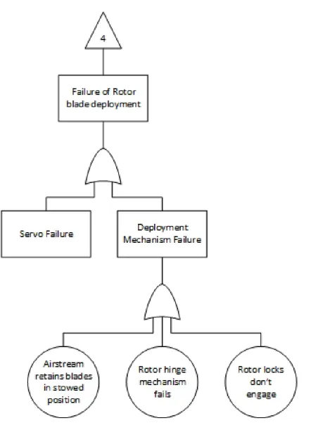
B.5 Deployment Failure . . . 64
D.1 Nose - 3D Printed . . . 71
D.2 Rotor Lock Tray - 3D Printed . . . 72
D.3 Rotor Lock - 3D Printed . . . 73
D.4 Nose Joiner - 3D Printed . . . 74
D.5 RDS Spindle . . . 75
D.6 Bottom Thrust Stop . . . 76
D.7 Lower Rest . . . 77
D.8 Quadrature Encoder Mask . . . 78
D.9 Rotor Head Top Rest . . . 79
D.10 Sensor Assembly Platform . . . 80
E.1 Schematic Battery Controller . . . 82
E.2 Schematic of Quadrature Encoder and Pro Mini Connector Boards . . . . 83
LIST OF FIGURES xiv
F.1 High Level Interconnect System Diagram . . . 86
F.2 Host FMU State Diagram . . . 87
F.3 Host Release Controller State Diagram . . . 88
F.4 RDS FMU State Diagram . . . 89
List of Tables
3.1 Excerpt from ref ARP4761, Figure D2 - Fault Tree Symbols . . . 14
B.1 System Safety Traceability Matrix . . . 61
G.1 Risk Management Chart for Ground Test Apparatus . . . 92
G.2 Risk Management Chart for Working at Heights . . . 93
G.3 Risk Management Chart for Work Place Safety . . . 94
G.4 Risk Management Chart for Impact of package onto structure or personnel during descent . . . 95
H.1 Type prefix . . . 97
H.2 Type modifier . . . 97
Nomenclature
∆N Number of observed pulses inside the observation window
Ω Rotor rotation rate
ΣTh−1 Time interval to the first observed pulse after the start of the observation window
ΣTh Time interval between the last observed pulse before the end of the observation
window
ΣTsc,acc Time of the basic or extended observation window
Chapter 1
Introduction
1.1
Motivation
Established as a part of the rules of the UAVOutBackChallenge competition, is the re-quirement to deliver a rescue package from an Remotely Piloted Aircraft System (RPAS) from a minimum height of 65m. This rescue package is to contain a minimum of 500ml of water. The safe delivery to a target point on the ground must account for both mini-mal package damage and safe human interaction during the package’s terminal trajectory phase. Existing methods which have been used are deployed parachutes or fixed autorota-tion vanes which reduce the impact velocity of the released rescue packages. These meth-ods are prone to variations in landing accuracy due to pre release trajectory calculation errors, inconsistent trajectory paths due to poor package aerodynamics and importantly, the variations in trajectory due to wind.
1.2 Aim 2
1.2
Aim
To design and prototype a device that can control and decelerate a package using an active autorotation technique from the rotary helicopter environment.
1.3
Objectives
The resultant prototype system shall be capable of:
1. carrying a quantity of 500ml of water within a commercial container,
2. accept and actively descent along a defined path to given target co-ordinates,
3. constrain the terminal landing velocity below 3 m/sec, and
4. provide an environment for safe carriage and purposeful release of the rescue pack-age.
The subordinate objectives include undertaking the project development considering a safe development environment and ultimately production of a safe product at the conclu-sion.
1.4
Context
CASA Civil Aviation Order 40.3.0 defines autorotative flight means a condition of flight without power when lift and rotor speed are derived from the action of the airflow upwards through the rotor system.
1.4 Context 3
failures. Given the emergency situation, the upward movement of airflow imparts kinetic energy into the rotor as the craft descends which is then translated into thrust close to the ground through a complex pilot initiated flare manoeuvre.
The autorotation technique has been pursued as a possible alternate deceleration tech-nique for landing spacecraft (Wernicke 1959), personnel (Lambermont & Pirie 1959) and provisions (AIA 2003). Interest in helicopter safety and Unmanned Aircraft Systems (UAVs) landing control have seen researchers pursue controlled autorotation as a means for safe landing of helicopters or UAVs in emergencies or as the basis for accurate de-livery to a given location. Research outcomes have proposed and validated algorithms to plan and execute the controlled glidepath and safe landing using optimisation tech-niques. Johnson, (Johnson 1977) derived a non-linear model that accounted for vertical and longitudinal movement. Johnson’s optimal control used a cost function that min-imised horizontal and vertical speeds on landing. This optimisation used forwards and backwards numerical integration between defined boundaries using the steepest descent method.
The objective of this project can be broken down into multiple facets:
1. Power Control
2. Communication
3. Target Transfer
4. Release Preparation
5. Release
6. Blade Deployment
7. Rotor Spin-Up
8. Autorotation Glide
9. Autorotation Flare
1.5 Ethics and Implications 4
1.5
Ethics and Implications
1.5.1 Engineering Ethics
The Engineers Australia Code of Ethics defines the values and principles that shape the decisions engineers make in engineering practice. Within the Code of Ethics are guidelines on Professional Conduct that provide a framework for members of Engineers Australia to use when exercising judgment in the practice of engineering.
The pursuit of an engineering solution to improve the process of rescuing people or sus-taining stranded people is seen by the Author as a humanitarian goal.
1.5.2 Prototype Readiness Implications
Though this engineering effort is focused on providing an alternate solution to methods of accurately deliverying supplies to stranded personnel, there are many issues to con-sider within the current aerospace regulatory environment. These issues such as software assurance must be addressed to satisfy airworthiness and safety regulations. This project provides a small insight into the broader effort a commercial product would require to be considered safe and fit for purpose.
1.6
Overview of the Dissertation
This dissertation is organised as follows:
Chapter 2 Previous Work,
Chapter 3 Establishing System Requirements,
Chapter 4 Rotary Deceleration System - Design and Construction,
Chapter 5 Prototype Verification, and
Chapter 2
Previous Work
2.1
Chapter Overview
This chapter discusses the basics of Navigation, Transfer Alignment and the Regulatory Environment that must be considered when developing the RDS prototype.
2.2
Previous Work
2.2.1 Navigation
Navigation control requires the understanding of basic navigation reference frames and the earths geometry. Positional control of the RDS both pre and post release requires the translation of the navigation information between these reference frames. The basic frame is the body of the RDS. This body frame is defined by three axes in which on board sensors are aligned that measure accelerations and angular rates. To control the RDS from a point in flight to a point on the earth, these body co-ordinates must be translated to the earth frame. Each of the navigation frames have specific purposes.
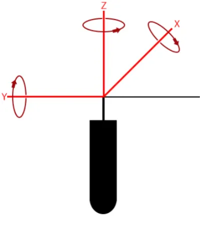
The Body Frame. The axes of the Body Frame at Figure 2.1 are:
1. The origin coincides with the Center of Gravity of the RDS.
2.2 Previous Work 6
Figure 2.1: Body Frame of RDS
3. The y-axis points forward longitudinally. This axis is called the roll axis.
4. The z axis points towards the vertical direction. Yaw angle is measured around this axis.
This frame is referred to as the b-frame. The Roll, Pitch and Yaw angles (RPY) around these Body Frame axes are known as the Euler angles. The RPY rotation angles corre-spond to rotations around each respective axis using the right hand rule.
Earth-Centered Inertial (ECI) Frame. The inertial frame as defined by (Grewal, Weill, & Andrews 2007) is stationary in space with its origin at the center of gravity of the earth. The axes of the ECI Frame are:
1. TheXECI is in the equatorial plane and points in the direction of the vernal equinox
,
2. The ZECI is parallel to the rotation of the earth coincident with the North polar
axis, and
3. TheYECI is orthogonal to theXECI andZECI axes and completes the right handed
2.2 Previous Work 7
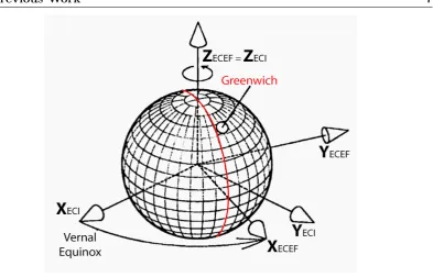
Figure 2.2: ECI and ECEF Frames
This is the frame of choice for near Earth environments. This frame is referred to as the i-frame.
Earth-centered Earth Fixed (ECEF) Frame. Referred to as the e-frame, the ECEF Frame shares the same origin and z-axis as the ECI Frame though rotates with the earth. The axes of the ECEF Frame and their relationship with the axes from the ECI frame are shown in Figure 2.2 taken from (Grewal et al. 2007). Specifically, these axes are:
1. TheXECEF, which passes through the equatorial plane and the Greenwich meridian.
2. The ZECEF passing through through the North polar axis, and
3. TheYECEF, and in the equatorial plane orthogonal to theXECEF andZECEF axes
and completes the right handed system.
Local Tangent Plane (LTP) coordinate systems represent local reference directions for RDS attitude and velocities. Two such right handed LTPs are the East-North-Up (ENU) and North-East-Down (NED) coordinate systems. The NED coordinate axes coincide with RDS Euler Angles (Roll Pitch Yaw) coordinates when level and the RDS is facing the North direction.
2.2 Previous Work 8
2.2.2 Transfer Alignment
To control and guide a RDS from an aircraft requires the knowledge of position, attitude, velocity, angular rate and accelerations. The aircraft and RDS will utilise IMU and Global Positioning Systems (GPS) to provide these inputs. The IMU measures then integrates specific forces and angular rates to gain knowledge of current position, velocity and at-titude. These actions must be inititalised with an accurately known starting point. As bias errors caused through measurement, manufacturing or introduced noise affects these integration algorithms IMU systems do not have long term accuracy. To compensate, long term stable information from GPS systems can be blended into the measurement process.
Both the RPAS and RDS will contain their own IMU and GPS units, and will be calcu-lating separate navigation solutions. The RDS however will be carried at 90◦ to forward flight such that the GPS unit may not correctly receive signals to provide this long term stability to the RDS’s Navigation solution. Accordingly, drift may occur with the RDS Navigation Solution. To correct this drift, Transfer Alignment can be used to calibrate and maintain the RDS (Slave) Inertial Navigation System (INS) from the host aircraft’s Master INS.
The quality of Transfer Alignment is a significant factor in the Military aerospace environ-ment as weapons are attached to the underside of metal aircraft. This position masks the weapon slave INS from receiving GPS signals (if fitted). A further factor in the military environment is that flight weapons that require control usually have quite small INS due to space constraints. These systems invariably are not activated until just prior to release and require initialisation of their navigation solution from the Master (more accurate) INS onboard the parent aircraft.
(Groves 2003) identifies the optimised Transfer alignment estimates:
1. Attitude and velocity;
2. Accelerometer and gyro static and dynamic biases;
3. Accelerometer and gyro scale factor and cross coupling erros; and
2.2 Previous Work 9
The transfer alignment algorithms utilise Kalman filters to provide estimates of the errors from the Slave INS to that of the Master. Further, as sighted within (Groves 2003) manoeuvres undertaken by the host aircraft during the alignment affects the performance of the estimation process. These manoeuvres isolate the states that are estimated by the Kalman filter. For example by changing altitude, error sources within attitude and velocity measurements can be observed.
2.2.3 Australian Aerospace Regulatory Regime
The Civil Aviation Safety Authority (CASA) has published regulations that pertain to Model and Unmanned aircraft within (CASA 2002). These current regulations were established in Jan 2002. The extension objectives of this project were proposed to be achieved through carriage of a RDS from a small UAV aircraft operating below 400 feet AGL outside controlled airspace in accordance with the (CASA 2002) regulations.
In May 2014 CASA released Notice for Proposed Rule Making (NPRM) 1309OS - Re-motely Piloted Aircraft Systems (CASA 2014) that proposes changes to these regulations. The NPRM introduces specific regulations for Remotely Pilot Aircraft Systems (RPAS) with aircraft weight between 2kg and 150kg that require CASA approvals and Operator Certification if operated outside the following standard operating conditions:
1. the RPA’s remote pilot can directly see the RPA, with or without corrective lenses, but without the use of binoculars, a telescope or other similar device; and
2. the RPAS is being operated below 400 ft AGL in VMC by day; and
3. the RPAS is not being operated within 30 m of a person who is not directly associ-ated with the operation of the RPA; and
4. the RPAS is not being operated:
(a) in controlled airspace; or
(b) in or over a prohibited or restricted area; or (c) over a populous area; or
2.2 Previous Work 10
Chapter 3
Establishing System Requirements
3.1
Chapter Overview
This chapter describes the development of system requirements for the delivery plat-form and the expected interaction with the host RPAS. This development accounts for considerations of system safety and the chapter details the corresponding safety related requirements that are imposed. The requirements encompass the hardware, software and interface between sub components.
3.2
Concept of Operations
To satisfy the objectives of the UAVOutbackChallenge a 500ml water container must be accurately dropped from a minimum height of 65m and the container must remain intact following the resultant ground impact. The rescue package size and shape must therefore be streamlined if externally carried to the drop point and needs to include some form of deceleration system to minimise the ground impact speed to an acceptable level. A further expectation of this project is to include navigation, guidance and control systems to ensure accurate delivery of the rescue payload under varying wind conditions. The likely carriage time during the transit to the release point is up to 50 minutes with a final descent flight time of about 30 seconds.
3.3 System Safety Analysis 12
dispatch and receiving ground personnel respectively.
Given this projects objective is to utilise Autorotation as the deceleration methodology and using helicopter rotor blades as lift surfaces, the drag from these rotor blades must be minimised during the carriage phase to the release point. Due to the expected length of rotor blades, the system is expected to be suspended external to a host RPAS. Accordingly, the system design must retain the blades conformal to the system body during transit to the release point, for deployment in the descent phase.
The ground objective position is expected to be passed to the system as part of the pre-release communication. Post pre-release requires controlled deployment of the autorotation decelerator, build-up and management of kinetic energy in the form of rotor angular velocity and translation of this kinetic energy into lift to minimise ground impact speeds.
The project is to include a system safety based requirements analysis phase to consider possible hazards related to safe carriage, authorised release and flight modes of the de-ployed system.
3.3
System Safety Analysis
Development of products that have safety implications require conformance to a System / Software Safety Standard. This project utilised elements of an earlier version (E) standard (DOD 2012) due to the disclosure of hazard analysis tasks that are missing from the current version. (DOD 2012) defines a series of management, development and reporting tasks to provide a consistent means of reporting risks. The limited subset of tasks incorporated into this development effort were:
1. Task 106 Hazard Tracking System
2. Task 201 Preliminary Hazard List
3. Task 202 Preliminary Hazard Analysis
4. Task 301 Safety Assessment Report
3.3 System Safety Analysis 13
The risk acceptance criteria was modified to incorporate involvement of the Project Su-pervisor in consideration of the exposed and treated risks, though no such involvement was necessary.
To satisfy the operational concept a System Safety analysis was undertaken. The results of this analysis determined that there were hazards related to the program of development and the eventual product.
Undertaking the safety analysis exposed safety related issues from the Workplace Health and Safety (WHS), and system safety disciplines. The WHS issues pertained to the phases of both development and test. The development phases included manufacturing requiring the manipulation of hand tools and machinery, whilst people involved in ground testing were exposed to moving parts. A further WHS hazard exposed was the requirement to briefly work at heights during the install the ground test stand apparatus at a height of 4m.
From a System Safety perspective, the solution can mitigate hazards exposed during development and test through a system safety design order of precedence:
1. Elimination through design selection,
2. Incorporation of safety devices,
3. Provision of warning devices, and/or
4. Development of procedures and training.
Workplace Health and Safety hazards are disclosed within Appendix G of this report.
The initial ground test phase exposed the physical hazards of moving parts, machinery and working at heights. System Requirements were raised to account for the mitigation to these hazards and are included in design of the ground test rig.
1. Moving parts;
2. Working at heights;and
3.4 System Safety Requirements 14
System Safety Analysis was undertaken using Functional Hazard Analysis (FHA)and the associated Fault Tree Analysis (FTA) techniques from (Aircraft, Dev & Committee 1996). As defined within (Aircraft et al. 1996) a FHA looks at system functions and combinations of system functions to identify and classify the associated failure condition(s). The FTA method is an analysis which focuses on one particular undesired event and deduces causes of this event. The FTA considers both loss of functions and malfunctions.
The FTA output is a graphical hierarchical representation of the relationships between failure effects and failure modes underpinning the single project system safety hazard. FTA are defined by two types of symbols, logic and event. Logic symbols, Boolean logic AND-gate or OR-gate, are used to link the various events of the Fault Tree together. The FTA event symbols are defined within Table 3.1.
Table 3.1: Excerpt from ref ARP4761, Figure D2 - Fault Tree Symbols
Event description of an output of a logic symbol or of an event
Basic Event Event which is internal to the system under analysis, requires no further development
Undeveloped Event
Event which is not developed further because it has little impact on the top level event or be-cause the details necessary for further event de-velopment are not readily available.
Transfer Indicates transfer of information.
3.4
System Safety Requirements
The process of undertaking an FHA identified a single hazard; Impact to Property or Human.
A System Safety FTA was conducted on this identified hazard. The resultant FTA is shown in Appendix B Figures B.1, B.2, B.3, B.4 and B.5 .
3.4 System Safety Requirements 15
mitigate the Hazard of impact to Property or Human are summarised below.
Figure B.1 identifies two possible causes of impact to property or humans; that of passing an incorrect Ground objective to the RDS and secondly, when given a valid ground target objective the RDS undertakes incorrect flight control actions during descent. The localisation and determination of the actual ground objective is not part of this project and is assumed to be valid, however, this project must account for correct transfer of target information from the host to the RDS. Accordingly, a System Safety requirement was established to ensure correct target transfer before the host RPAS releases the RDS.
SSR1: The System shall validate the specified target co-ordinates have been correctly passed to the RDS prior to release.
The hazards second causal factor of incorrect flight control actions has multiple sources which are exposed in a series of subordinate FTA branches, Figure B.2, Figure B.3 and Figure B.4. Hierarchically the highest branch is Figure B.2. Incorrect RDS flight control can be caused by either loss of control or release of the RDS outside of controllability limits.
Breaching controllability limits could be due to the lack of readiness of the RDS flight state or the release point is too low, airspeed too fast or the RDS simply can not reach the target due to the distance between release point and target.
To mitigate the breach of controllability limits the RDS or host could validate that the launch region and release flight criteria are within defined limits prior to release. Accord-ingly safety requirements are defined as:
SSR2: The System shall ensure the RDS release conditions are within defined limits prior to release. SSR3: The System shall ensure that the RDS is in a functional state appropriate for release.
A further two factors underpin the possible loss of control; a critical component failure or the failure of the system to adequately control the descent phase of the RDS.
3.4 System Safety Requirements 16
swashplate or linkages and the rotor deployment mechanism. Within Actuator failure, electronic failures could be within the servo itself or the origin command system within the Flight Management Unit. Servos directly manipulate the swashplate, controlling roll, pitch and collective. Failure of the servos to accurately translate command signals to physical swashplate movements through delay or malfunction would cause loss of control. No mitigation exists should any actuator fail during descent. No failure detail could be located about the specific servos used in the design or FMU failure rates so this event was identified as undeveloped. A solution may be the undertaking of specific failure analysis on these items before product commercialisation is undertaken.
The exposure timeframe to a power supply failure is limited to the descent of about 30 seconds. Power Supply failure analysis identified battery failure and circuit failure as possible causes. No evidence was found of manufacturers Mean Time Between Failure (MTBF) data of battery systems used in model equipment so this event was identified as undeveloped. Analysis focused on defining a requirement to establish confidence in RDS supply availability and remaining capacity during the carriage phase:
SSR4: The System shall verify RDS power supply availability and remaining capacity are within correct boundaries prior to authorising release.
The remaining causes of Critical Component Failure were predominately mechanical in nature and are constrained by commercial availability. To mitigate component failures within actuators and flight mechanism (rotor blades, swashplate or linkages), commercial hobby resellers were approached to gather information on the nominal hobby swashplate, rotor heads, rotor blades, servo torque and speed capacities that are used in commercial model helicopters of a similar physical size and weight. This informed the purchasing process of items used in this project. As the rotor deployment mechanism is to be designed within this project so its development must consider mitigations to the causes of rotor blade deployment, hinge mechanism and rotor lock engagement failures.
SSR5: The Rotor Deployment mechanism shall force the rotor blades into the airstream following release.
3.5 System Requirements 17
Verification chapter, Chapter 5.
Two causes were identified for the Failure to adequately control event; Sensor failure and anomalous Software function. The window of exposure to Sensor failure is both during the pre-release and descent phases as sensor data is expected to be used when confirming RDS release readiness as well as for guidance and navigation during descent. Anomalous software function, through incorrect specification, or failure to satisfy the specification could contribute to a failure event. Software Testing is presented within this project to provide an increased level of assurance in mitigating this possible event.
A component of self check is considered appropriate for inclusion to mitigate these two possible events. Accordingly, the last safety requirements are:
SSR6: The System shall carry out periodic Built in Test (BIT) functions on guidance, control and navigation sensors prior to authorising release.
SSR7: The system shall utilise self checking software logic to confirm correct operation prior to authorising release.
3.5
System Requirements
System Requirements, disclosed within Appendix C, have been segmented into the fol-lowing objective areas:
1. Navigation,
2. Power Supply,
3. Physical,
4. Interface,
5. Built In Test, and
3.6 Chapter Summary 18
3.6
Chapter Summary
Chapter 4
Rotary Deceleration System
-Design and Construction
4.1
Chapter Overview
This chapter discloses the design process and outcomes within the physical, electrical and software discipline related activities undertaken within this project to design and construct the Rotary Deceleration System (RDS). The detail is referenced in diagrams, drawings and software listings contained within the attached Appendices. Finally, a section on critical analysis is discussed that identifies recognised flaws in the design and implementation process and resultant outcomes.
4.2
Physical Design
The RDS design is segmented into six sub-assemblies:
1. Nose Assembly, containing the power supply, controller and regulator;
2. Rotor Lock Assembly, retention of Rotor blades conformal to the RDS body;
3. Body Assembly containing the payload, host interconnect and wiring loom;
4.2 Physical Design 20
5. Rotor Assembly containing the actuators, spindle and rotor lift and control compo-nents (swashplate, alignment, rotor head and blades); and
6. Sensor Assembly situated above the rotor head. The Wiring loom routes to the sensor assembly from the Electronics assembly through the rotor spindle.
These assemblies were designed using the 3D CAD modeling package AutoDesk Innovator (Student Version). The Innovator CAD application allows the export of completed designs to .stl format which were dispatched for 3D printing. In all, the following components were manufactured using 3D printing services:
1. Nose,
2. Battery holder,
3. Lock tray,
4. Rotor lock,
5. Rotor lock interconnect,
6. Nose joiner, and
7. Rotor blade holder, pivot and lock.
3D printing allowed for complex shapes to be developed and manufactured simply and quickly. An example is that of the Nose cone which has a cylindrical slot that the battery holder slides into, Figure D.1. This allows for bench testing of the battery system without the bulk of the Nose cone. The available space within the Nose cone is used to stow the Regulator, batteries and Power Controller. Close inspection of shows the set of four keyed attachment lugs that allow simple detachment of the Nose from the Rotor Lock assembly to access power supply and Rotor Lock components.
The printed Rotor Holder, Pivot and Lock is shown in Figures 4.1 and 4.2 .
Figure 4.3 provides a cross section view of the Nose and Nose joiner component internal structure.
4.2 Physical Design 21
Figure 4.1: Deployed Position
Figure 4.2: Conformal Position
The Rotor Tray bolts to the Nose Joiner and positions the Rotor Lock shown at Figure 4.5. When in the locked or closed position the ends of the Rotor Lock fit into slots within the Rotor Tray to provide strength and stability against release due to vibration.
An original project expectation was to machine as many components from Aluminum as possible to establish a prototype that would survive as many test activities as required. Due to cost restrictions this was not achievable. The risk of using the 3D printed rotor holder, pivot and lock components was considered too high and all verification activities were undertaken without those components. Regardless, as the project did not achieve as many original objectives, the fact of not using these components did not detract from the results of testing undertaken.
4.2 Physical Design 22
Figure 4.3: (a)Nose Cone. (b) Nose Joiner.
Figure 4.4: (a)Rotor Tray Top View. (b) Rotor Tray Bottom View.
1. Spindle,
2. Actuator bracing,
3. Bottom thrust stop,
4. Rotor lower rest,
5. Rotor holder,
6. Quadrature encoder mask, and
7. Rotor top rest.
The mechanical drawings for each of these items are contained within Appendix D. The complete assembly can be seen in Figure 4.6.
4.3 Electronics Design 23
Figure 4.5: 3D Rotor Lock
these bearings the various components of the rotor assembly are positioned and are free to rotate, refer Figure 4.6. Two sets of 8mm ID x 16mm OD thrust bearings are used to contain the rotor head components vertically on the spindle and are held in place by the Rotor Lower and Upper Rest components. A number of radially positioned grub screws within the Rotor Upper Rest hold the whole rotor assembly together. This containment design is the weakest facet of the design as slippage of the grub screws would allow vertical separation of the rotor head assembly and resultant loss of RDS.
The RDS platform is to use a three point swashplate to control the roll, pitch, and col-lective through Servo Cyclic and Colcol-lective Pitch Mixing (CCPM), referred to as servo mixing. Servo mixing in software provides a mechanically simpler design without sacri-ficing accuracy. Three servo actuators are situated below the swashplate as per model helicopter designs. The CCPM swashplate design was chosen for simplest assembly and associated functional support within common Flight Management Unit open source soft-ware.
The sensor assembly is attached to the Rotor Upper Rest with the wiring loom routed through a center hole to match the spindle tube.
4.3
Electronics Design
4.3.1 System Architecture
4.3 Electronics Design 24
Figure 4.6: RDS Lift Guidance Mechanism Assembled
application has a ground based controller software package also open source, Mission Planner. The APM:Copter application is intended to be hosted on another open source hardware product; the PX4 FMU and daughter board PX4IO. For the sake of simplicity for the remainder of this report the combination of PX4FMU and PX4IO daughter board will be called FMU.
The DO-178B standard (States 1993) provides ”guidance for determining, in a consis-tent manner and with an acceptable level of confidence, that the software aspects of airborne systems and equipment comply with airworthiness requirements”. Of interest to this project, DO-178B identifies two techniques called Partitioning and Safety Moni-toring. Inclusion of partitioning in the design accounts for the isolation of functionally independent software components so as to contain and/or isolate fault conditions. Safety Monitoring protects against specific failure conditions by directly monitoring a function for failures which would contribute to the failure condition.These two techniques were used within this project. Specifically, parallel independent initiation and detection of the readiness of the RDS for release, and monitoring of aspects of sensor or power supply data to ensure critical components are operating correctly prior to release.
4.3 Electronics Design 25
and functional allocation as identified within Figure F.1. Readiness for Release and Built in Testing satisfies two System Safety Requirements. Readiness for Release is achievable through two functionally independent communication links. The first via serial commu-nication between FMUs, whilst the second is via discrete signals between Sensor Manager and Release Controller. Without the Release Controller receiving confirmation through these two methods release is not initiated.
The constant review of Built in Test results from all processor boards provided assurance of correct operation prior to release.
Considering Figure F.1, the allocation of functions is as follows:
The Host FMU is responsible for flight control management of the host RPAS. The FMU interfaces to host systems and sensors for RPAS navigation, guidance and control of all host functions. The RDS system is to compare and align to the master host FMU navigation solution. The Host FMU has communication links to the ground station controller and provides status and command link for management of RDS release.
The RDS FMU is the master controller of the RDS. The RDS FMU interfaces to the Host RDS via Universal Asynchronous Receiver/Transmiter (UART) serial communica-tion protocol. Similarly to the host FMU, once the RDS is released the RDS FMU uses information from RDS sensors (GPS / Compass / Accelerometers and rate gyros) for flight guidance, navigation and control.
Each FMU can communicate using UART and I2C serial communication protocols. The FMU is the master I2C node whilst it can be a Master or slave on the UART serial link.
The Sensor Manager is a slave on the RDS I2C serial network. The RDS Sensor Manager controls and receives status information from the Power Controller. The Sensor Manager also collates status information from the host interconnect and independently controls the Commit to Release discrete to the host. The RDS Sensor Manager presents status information to the RDS FMU for the following functions:
1. Host connection interlock and debug signals
2. RDS power
4.3 Electronics Design 26
4. Rotor head speed and direction.
The Host Release Controller is a slave on the Host I2C serial network. Similar to the RDS Sensor Manager, the Host Release Controller (RC) controls and receives status information from the host power controller, RDS interconnect and controls the Release, Lock/ Unlock and Extension servos. The Release Controller independently determines and notifies the Host FMU of RDS assertion of Commit to Release.
Both of the Sensor Manager and Relesae Controller utilise the same core Operating System and classes to achieve the assigned functions. Slight modification are introduced into each to support some unique functions.
4.3.2 Processor Selection
The FMU provides adequate memory and speed capacity to undertake this project. The FMU has on board 3 axis accelerometers, rate gyros and compass. The FMU also connects to external GPS, Compass and communication subsystems.
The space considered available to undertake the independent release readiness checks and communication required identification of a small processor footprint that had rela-tively high throughout, sufficient Input/Output (I/O) discrete, Pulse Width Modulation (PWM) capabilities and 5V power supply tolerance. The Arduino Pro Mini utilises the 16MHz ATmega328P processor at 5V and has 32K Flash, 1K EEPROM and 2K inter-nal Flash memory. The circuit board footprint is 18x33mm due to elimination of IDE programming interface logic. The Pro Mini has 8 Analog and 14 Digital I/O pins, with each of the Digital I/O pins capable of setup as an interrupt. An additional advantage is that the board does not come pre-populated with connector pins, which is an important aspect allowing attachment to the RDS Sensor Assembly and FMU wiring loom through specific low profile DF13 connectors.
Nil-4.3 Electronics Design 27
RTOS is open source and is unproven in terms of correct verifiable operations, however, would provide the project with the ability to leverage off multiple independent functional threads to carry out the Safety Monitoring whilst supporting Quadrature Encoder inter-rupts and serving the I2C communications port. No specific testing was undertaken to verify NilRTOS operation beyond RDS functional testing.
4.3.3 Power Controller
Design requirements identified that the power controller needs to be powered from the internal battery at all times to enable control of the power output regardless of connection to the Host RPAS, as would be the case during descent. Control of external and internal supply by the power controller board would be commanded through digital 5V logic levels enable signals.
The following is a description of the Power board, Figure 4.7 operation and associated component involvement . Refer to Appendix E Figure E.1. Internal RDS battery sup-ply is two LiFEP04 batteries in series configuration providing 6.4V DC with capacity of 1300mAh. LiFEP04 was selected for its high density, low cost, low toxicity and high thermal stability, (Dupr, Martin, Degryse, Fernandez, Soudan & Guyomard 2010). Pass-ing through a commercial 5V regulator the internal power supply is connected to the Power Controller board via connector J3. External power is passed through the RDS wiring loom and connected to the Power Controller Board via connector J1. RDS Power is available at connector J2 and passes back through the wiring loom to the Electronics assembly.
The power controller circuit includes selection and status monitoring of external and in-ternal power. Inin-ternal power monitoring includes monitoring of battery remaining charge capacity and voltage level. Selection of power supply source is achieved by two discrete input signals which enter the Power Controller board on a single six pin connector J4. J4 also includes status and monitoring signals presented to the wiring loom. A Hirose DF13 connector is used to provide security of cabling in the vibration environment whilst Hirose DF3 are used for the higher current power routing.
4.3 Electronics Design 28
U3 controls two discrete N-channel MOSFETs emulating an ideal diode. U3 has Enable inputs EN1 and EN2 (Active Low) that control the availability of the corresponding power supply to the output connector J2. U1 provides for Opto-isolated translation of external power application into a sensed voltage level as an inverted logic signal to U2 input B. The External Power Supply enable signal, is applied to the other U2 input, input A from connector J4. When the External Power Supply enable signal is LOW, U2 passes the state of the external supply through to U3 EN1. Accordingly, when external supply is available and U2 Input A is LOW the U1 signal state is presented to turn on U3 supply 1 (External supply). In contrast, if the External Power Supply enable (U2 input A) is asserted HIGH, U3 turns off the associated MOSFET and high current external supply is disabled.
Figure 4.7: PowerControllerImage
U1, U2 and pull-down resistor R3 provides for automatic external power application during start-up of the Sensor Manager.
EN2 is connected to the Internal Power Supply enable signal and is defaulted to the enabled state (Active LOW) via the pull-down resistor R4. This condition is required should any interruption of internal power be realised during descent. When power is recovered this default LOW will immediately pass internal power supply to RDS circuits.
U4 provides for measuring of current and voltage of the internal battery. These status signals are presented to external use on connector J4.
4.3.4 Pro mini Connector and Quadrature Encoder Sensor boards
4.3 Electronics Design 29
Hirose DF13 that have sufficient current capacity to carry the interface signals and single rotor lock servo signal line.
Figure 4.8: ProMiniwithConnectorBoard
The Quadrature Encoder Sensor board, Figure 4.9, is a small circuit with three compo-nents. Appendix E Figure E.2 contains the schematic. The two sensor boards receive their power and ground connections from the common Battery Controller supply out-put, nominally 5V DC. Resistors R6 and R7 establish the necessary forward bias current through the opto sensor. The sensor has a 3mm air gap between Infrared (IR) source and sensor diode within which the Quadrature Encoder mask spins. Two 3mm mounting holes attach each sensor to the underside of the Sensor Assembly and lock the relationship of sensor to mask consistently. The wiring loom connects to the sensor boards using Hirose DF13 connectors.
Figure 4.9: QuadratureSensor
4.4 Software 30
4.4
Software
4.4.1 Interface Design
An Interface Control Document disclosed within Appendix I was written to define all possible communication between each of the sub systems shown in the System Archi-tecture Diagram, Figure F.1. The Interface Control Document assigns the interconnect discretes and pin layout between the Host and RDS and the communication messages be-tween Host and RDS FMUs, RDS FMU and Sensor Manager and Host FMU and Release Controller. The inter FMU communication uses the UART serial protocol, whilst FMU to Sensor Manager and FMU to Release Controller is via I2C, with the FMU in each later case as the I2C Master Node.
Identification of communication direction, regardless of UART or I2C protocol is in rela-tion to the Slave Nodes. That is, Recieve (Rx) messages are those expected to be received by the Slave from the Master, whilst Transmit (Tx) messages are requested from the Slave by the Master Node. In summary, six Rx messages are used to transmit commands from the RDS FMU to Sensor Manager. They are:
1. Msg 1: Used to notify the slave I2C node of the Message Identifier in the subsequent Tx Msg request. This allows the Slave Node to prepare the Tx buffers with the required data;
2. Msg 2: FMU Controlled State change request;
3. Msg 3: Weight off Wheels status;
4. Msg 4: Initialisation of Power Supply capacity. Intended to originate from the ground station and routed through the FMUs on power application;
5. Msg 5: FMU State Change Acknowledgment. Intended for use by the FMU to acknowledge Sensor Manager critical state changes; and
4.4 Software 31
Six Tx messages are identified for transmiting Sensor Manager status information back to the RDS FMU. These are:
1. Msg 0: Sensor Manager State;
2. Msg 1: Quadrature Encoder Speed and Direction;
3. Msg 2: Internal Battery Current Usage;
4. Msg 3: Power Mode State. Identification of Selected Power Supply Source;
5. Msg 4: Built In Test Result; and
6. Msg 5: Interlock status. These include RDS Interlock Status, Debug and Commit to Release Interlock Status.
The Host Release Controller uses many of the same software functions as the Sensor Manager and in-turn many of the Rx and Tx messages have the same intent. Whilst the Sensor Manager manages the Power, Quadrature Encoder, Rotor lock actuator and the RDS side of the interlock connector, the Release Controller manages the same type of power controller, three servos for release, lock/unlock and connector extension and the Host side of the interlock connector.
The Host Release Controller has 5 each of Rx and Tx messages. In summary Rx messages are:
1. Msg 1: Used to notify the slave I2C node of the Msg Identifier in the subsequent Tx Msg request. This allows the Slave Node to prepare the Tx buffers with the required data;
2. Msg 2: FMU Controlled State change request;
3. Msg 3: Weight off Wheels status;
4. Msg 4: RDS Functional State; and
4.4 Software 32
Release Controller Tx messages are:
1. Msg 0: Sensor Manager State;
2. Msg 1: Host Battery Supply Amount;
3. Msg 2: Power Mode State. Identification of Selected Power Supply Source;
4. Msg 3: Built In Test Result; and
5. Msg 4: Interlock status. These include Host Interlock Status, Debug and Received Commit to Release Interlock Status.
Three sets of discrete signals are critical to operation, safe carriage and release, refer Appendix I Table 7. These are the Host Interlock and RDS Interlock discrete and the Commit to Release. All three are active LOW so that, should the InterConnector separate causing loss of connection, (which may cause signals to float), the state of each interlock would not be seen as valid active signals. The Host Interlock discrete pins are earthed within the RDS and vice versa the RDS Interlock discrete pins are earthed within the Host RPAS. Connection of the Host to RDS through the Interconnector, mates the two interlocks for their respective Sensor Manager and Release Controller function.
The Commit to Release discrete signal originates from the RDS Sensor Manager when Sensor Manager determines that the RDS FMU and itself are in the correct state for release. Should a request to Assert the Commit to Release discrete come from the RDS FMU before the correct timeframe, the Sensor Manager causes a BIT Fail event to oc-cur and the Release Process is halted until recovery action is undertaken. The Release Controller senses the assertion of the Commit to Release and notifies the Host FMU of overall readiness for release. Similarly, should the Release Controller sense the assertion of the Commit to Release in the wrong sequence of Release, the Release process is halted and the system must re-initialise the Release States within all four processors.
4.4.2 Software Design
4.4 Software 33
have independent functional allocations, though are tightly coupled to achieve RDS safe carriage and release.
The following describes the functional elements that have been completed within this project so far. These elements relate to the Sensor Manager and Host Release Controller. Appendix H contains the source listings for both units. Those software classes that are the same in both units are not repeated within the Host Release Controller Listing.
The software is based upon the Arduino sketch and associated libraries. The main pro-grams are SensorManager.ino and HostReleaseController.ino. These sketches include in the remaining C++ classes that complete the functionality. These sketches define the structure of NilRTOS threads, semaphores and Task Control Blocks and the rates and sequence of rate based functionality at 10Hz, 5Hz and 1Hz intervals. The sketches con-figure the usage of interface pins and establish the I2C message buffer system. Interrupts that manage the I2C communication are also first enabled with these sketches.
The Commander class inherits the functions of StateMachine, Power and Interface classes to effect overall functional control of the unit. The Commander class contains the func-tionality that is executed at the 10Hz, 5Hz and 1Hz rates and includes all sequence logic necessary to achieve the State Machine defined by Figure F.5.
The Commander class implements the Quadrature Encoder speed measurement algo-rithm, 4.1 presented within (Petrella & Tursini 2008). This iterative algorithm uses a mix of time and frequency measurements for accurate speed measurements.
Ω = ∆N
ΣTsc,acc+ ΣTh−1−ΣTh
· 60
Np
[r/min] (4.1)
This algorithm allows the observation window to be extended to give accurate measure-ments at low speed, critical to the start-up sequence of the rotor head. Importantly the one algorithm can be used for low and high speed measurements.
4.4 Software 34
The StateMachine class contains all necessary functionality to change the current func-tional state, including validation that the requested target state is a valid transition from the current state. StateMachine functionality is called when State changes are attempted. The State change validation process uses a network graph adjacency list, which represents all of the valid and invalid StateMachine transitions. Should an invalid state change be attempted, StateMachine functionality causes a Built in Test fault to occur.
The Interface class contains attributes and methods that manage the discrete signals to and from the Host Interconnect.
The Power class manages the Power Controller. Power methods include power supply selection, internal battery capacity measurement and current fault detection.
The BIT class undertakes and records current BIT results, either at the time of an asyn-chronous event like the above Invalid State change or at 1Hz. BIT results are maintained and presented to the I2C interface when changed.
The I2CBuffer class receives and prepares communication for the I2C interface. All classes that have status information to be sent to the FMU call on methods within the I2CBuffer class to format and buffer the information for transmission.
The Rotor blade conformal lock / unlock is achieved through use of methods within the ServoTimer2 library. This is an open source library which was modified slightly to integrate with the RTOS, NilRTOS.
The Release Controller uses the same set of classes to achieve its requirements, though most are modified due to alternate state sequence or interface needs. The Commander includes a software debounce algorithm to assist the action of a ground operator to attach the RDS to the Host RPAS. Three servos are now managed by the Release Controller.
4.4.3 Software Operation
4.4 Software 35
then immediately transition to the PackageCheck State. The Release Controller waits within the PackageCheck State until it detects Ground operator intervention through depression of the Load switch and confirmation that the Host RPAS is on the ground via receipt of Weight on Wheels by a Host FMU message. To load an RDS onto the Host RPAS, the Release Controller must first unlock then open the suspension hook. The Release Controller then confirms RDS connection through detection of the Active LOW Host Interlock discrete and initiates closure of the suspension hook and re-locking the safety actuator. The Host FMU meanwhile, Figure F.2, will stay in the Initialise State until the Release Controller reports its transition to the PackageCheck State. The Host FMU will then transition and wait in the HRCReady State until confirmation that the RDS is connected and suspension hooks closed and locked. The Release Controller enables Host DC supply through the Interconnect and reports an RDS is connected to the Host FMU. The Host FMU then transitions to the PackageConnected State and will wait therein until the RDS is to be tasked with a Ground Target location.
Before connection to the Host RPAS the RDS local power supply is turned on via external switch. The RDS FMU and Sensor Manager initialise to the Initialise State, refer Figures F.4 and F.5 respectively. Similar to the Host FMU, the RDS FMU will remain in the Initialise State until the Sensor Manager reports transition to the Prepared State. The Sensor Manager transitions to the Prepared State on detection of the RDS Interlock Active LOW due to connection to the Host RPAS. Any subsequent loss of this RDS Interlock signal outside of the ReadyConfirm or ReadyRelease States will cause the Sensor Manager to report a BIT Failure and transition to the BITFail State.
On notification that the Sensor Manager has transitioned to the Prepared State the RDS FMU will transition to the TransferReady State and awaits Ground Target tasking transfer to start from the Host FMU.
At the culmination of transferring and validating the tasking information, the RDS and Sensor Manager will be at the Tasked and ReadyConfirm States whilst Host FMU and Release Controller will be at Tasked and PackageConnected(PowerOn) States respectively.
4.4 Software 36
the BIT Fail reason is cleared.
On receipt of the external RDS Release Command from the Operator Ground Station the Host FMU dispatches to the RDS FMU a ReadyRequest command. The Host FMU transitions to the ReadyConfirm State and waits therein until the Release Controller reports that it has transitioned to the ReleaseConsent State.
Receiving the ReadyRequest command from the Host FMU causes the RDS FMU to command the Sensor Manager to the ReadyRelease State. Given no BIT Faults exist the Sensor Manager would transition to the ReadyRelease State wherein the Commit to Release discrete is asserted to the Host Release Controller. Whilst in the ReadyRe-lease State the Sensor Manager continues BIT Checks at 1Hz. Detection of BIT Failure would immediately cause the Sensor Manager to transition to the BITFail State and the invalidation of the Commit to Release signal.
Successful transition of the Sensor Manager to the ReadyRelease State allows the RDS FMU to transition to its ReadyRelease State which is reported to the Host FMU and in-turn to the Release Controller. It is the independent function of the Release Controller that now confirms concurrent assertion of the Commit to Release discrete and that the RDS FMU current State is ReadyRelease. When concurrent assertion occurs, the Release Controller State transitions to ReleaseConsent. Whilst in the ReleaseConsent State the lock/unlock safety is physically removed from the suspension hook actuator. The Host FMU now transitions finally to the ReadyRelease State and awaits there until the RPAS moves to the release point. It is during this final ReleaseConstent period that the hazard of inadvertant release is now exposed due to the suspension hook safety unlocked condition.
When finally at the release point, the Host FMU transitions to the ActionRelease State and commands the Release Controller to open the RDS suspension hooks. One second later the Release Controller determines if the RDS has actually parted from the Host and determines Gone or Hung status. A Hung status will be where the RDS has not fallen away for some reason. Following Hung/Gone determination the suspension hooks are again closed and locked.
4.5 Critical Design Analysis 37
and the Sensor Manager transitions to the Separation State. Within the Separation state the Sensor Manager suspends further BIT, enables the Quadrature Encoder interrupts and initiates a one second timer to allow for a period of separation before deploying the rotor blades. The RDS FMU is notified of release via the transition of the Sensor Managerto the Separation State. On timeout of the one second timer, the Sensor Manager transitions to the Deploy State and initiates deployment of the RDS rotor blades by actuating the rotor unlock servo. The Sensor Manager measures and reports the Rotor speed until the RDS FMU commands the transition to the PowerDown state.
On detection of Sensor Manager Deploy State transition, the RDS FMU transitions im-mediately to its Deploy state. Its role is to manipulate the collective pitch of the rotor to spin-up the rotor in the right direction until a nominal rotor head speed is confirmed. The RDS FMU tranistions to MidCourse State and navigates to the required ground task point using a balance of the kinetic energy whilst retaining sufficient energy to undertake a final flare manoeuvre. When an altitude limit is breached the RDS FMU transitions to the Flare State and initiates minimisation of vertical velocity through the flare manoeu-vre before ground impact. On detection of ground impact the RDS FMU commands the Sensor Manager and itself to PowerDown.
Abort conditions are supported by the design during pre-release phases. Abort transitions the Host and RDS FMU units back to TransferReady whilst the Release Controller and Sensor Manager return to PackageConnected(Power On) and Prepared States respectively.
4.5
Critical Design Analysis
3D CAD modeling provided significant opportunities to manipulate alternate design so-lutions, though the learning curve to achieve simple tasks was much more extensive than originally planned. So too was the translation of a 3D model to reality. The selection of wall thicknesses, even though utilising tool functionality to calculate proposed ressul-tant weights, caused significant weight increases when reality did not match modeling techniques. Test runs could have been attempted in order to validate the modeling and manufacturing process before final designs completed.
4.5 Critical Design Analysis 38
of prototype development caused significant impact to moving to the next stage in this project. An issue not lost on the author as alternate plans needed to be more thought through to enable work to continue on other facets whilst the delayed facet was resolved.
The decision to position the Sensor Package above the rotor blade may have simplified the measurement of Rotor head angular velocity but it introduced significant constraints and iterations of design. The nature of testing which is described in a later Chapter on verification identified a significant flaw in the Sensor Platform and Rotor top rest design. Further, the design idea of routing wires through the spindle may seem reasonable, however, the manufacturing capabilities required to bore a 3mm hole through a 5mm rod 150mm long is significant and not considered by the Author when making the original design decision. The alternate use of mixing 5mm OD x 3mm ID carbon fibre tubing with the base of the spindle succeeded in solving that problem however introduced the weakness in the Sensor Platform / Rotor Head design.
In regards to the electrical design another flaw detected during verification was the critiical decision to use the TLC4353 Ideal diode as the power controller. Though expecting to simplifying the method of control and parts count, a basic flaw in design was to not take into account pass through current due to the N-Channel MOSFET body diodes when the output was disabled. Though the Power Controller software interface expected power to be removed, the body diodes allowed power to remain present causing verification failures and the basic inability to turn off supply when commanded. A more appropriate alternate would be the use of P-Channel and N-Channel MOSFET load switches with minimal additional circuitry to provide the BIT status functionally the original design requires.
Developing and co-ordinating the manufacturing of the printed circuit board (pcb) de-signs provided the ability to tailor the circuit specifically to the need both in size and functionality. The process of pcb manufacturing can lead to implementation errors that are difficult to detect until the completed pcb is returned. The Author recognises that a detailed review of pcb design tool reports could have assisted detecting the common power rail anomalies that required circuit repair after the completion of stuffing the electronic components onto the board.
4.5 Critical Design Analysis 39
timing to achieve software development for all units was thought to be achievable. Life has many ways to intervene and the most appropriate action is to re-plan and progress with realistic goals. The two units, Sensor Manager and Release Controller, completed in this project’s timeframe have in the most part been verified to achieve the established System Requirements. There is realistically a significant amount of work to complete the overall project though.
4.6 Chapter Summary 40
4.6
Chapter Summary
Chapter 5
Verification
5.1
Chapter Overview
This chapter describes the development of a ground test facility useful to undertake dy-namic lift and flare verification activities. It further describes the minimal set of system tests that verify a number of System Requirements. Finally a short critical analysis of the test facility design is undertaken.
5.2
Verification Test Facilities
A test facility has been designed, based upon (Slaymaker & Gray 1953) and built to provide for prototype verification activities. The design allows capability that can impart an adjustable angular velocity to the rotor head and to allow autorotation tests within the vertical dimension, being constrained laterally.
As defined within the preliminary design section the rig is to be attached to a building wall to provide overall rigidity.
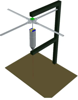
As access to a wind tunnel of sufficient size was not feasible during this project, the overall intention was to utilise this test rig to determine lift versus pitch and flare characteristics in an informal manner. The design layout is seen within Figure 5.1 for the lift testing.
5.2 Verification Test Facilities 42
Figure 5.1: Ground Test Lift Analysis Rig
completed test facility during a test run.
The Test rig design includes:
1. A vertical spine, adjustable using three 2.1m segments,
2. A top fixed horizontal drive and guide wire attachment beam,
3. A lower horizontal support beam, adjustable in the vertical plane from the base up to the upper beam,
4. A base, and
5. Vertical guide wire between the upper support beam and base that passes through the RDS and lower support beam.
5.2 Verification Test Facilities 43
Figure 5.2: Ground Test Lift Analysis Rig
5.2 Verification Test Facilities 44
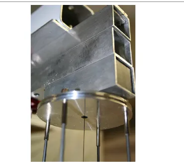
Figure 5.4: Upper Beam showing pre-load drive unit, Ian Saxby 2014
of the spine against a building wall. The adjustable height of the rig is setup depending on the use of the facility. The spine is designed to be supported at the base and upper end to allow the lower horizontal supprt beam to travel the full extent of the spine during the autorotation test cases. The extreme top of the rig spine is attached to guy ropes similar to radio mast fixtures to fix the rig vertically.
The top horizontal drive beam, includes the drive battery, Electronic Speed Controller (ESC), A Redback 91 size Brushless DC (BLDC) motor, pre-load rotary drive mechanism and Guide wire attachment point. When required the BLDC spins the pre-load rotary drive through a belted drive train at a ratio of 5:1. The pre-load rotary drive, as shown in Figure 5.4, uses a series of four metal wire fingers to impart the rotary motion onto the rotor head from the drive motor. The expectation is that the drive fingers allows for small vertical movements of the RDS during lift tests, and unimpeded downward movement during autorotation tests once the lower support beam is dropped away.
The Guide wire is passed up through the centre of the rotary drive mechanism and held centred to the rotary bearing, Figure 5.5.