i
LOW-COST AUTOMATIC HEADLIGHT DIMMER SYSTEM
KHAIRUL HAZWAN BIN ABU BAKAR
This report is submitted in partial fulfillment of the requirements for the award of Bachelor of Electronic Engineering (Computer Engineering) With honors.
Faculty of Electronic and Computer Engineering Univesiti Teknikal Malaysia Melaka
ii
UNIVERSTI TEKNIKAL MALAYSIA MELAKA
FAKULTI KEJURUTERAAN ELEKTRONIK DAN KEJURUTERAAN KOMPUTER
BORANG PENGESAHAN STATUS LAPORAN PROJEK SARJANA MUDA II
Tajuk Projek : LOW-COST AUTOMATIC HEADLIGHT DIMMER
SYSTEM
Sesi
Pengajian : 2005/2009
Saya NAJMI AZFAR BIN MOHD ROSLI mengaku membenarkan Laporan Projek Sarjana Muda ini disimpan di Perpustakaan dengan syarat-syarat kegunaan seperti berikut:
1. Laporan adalah hakmilik Universiti Teknikal Malaysia Melaka.
2. Perpustakaan dibenarkan membuat salinan untuk tujuan pengajian sahaja.
3. Perpustakaan dibenarkan membuat salinan laporan ini sebagai bahan pertukaran antara institusi pengajian tinggi.
4. Sila tandakan ( √ ) :
SULIT* (Mengandungi maklumat yang berdarjah keselamatan atau kepentingan Malaysia seperti yang termaktub di dalam AKTA RAHSIA RASMI 1972)
TERHAD* (Mengandungi maklumat terhad yang telah ditentukan oleh organisasi/badan di mana penyelidikan dijalankan)
TIDAK TERHAD
Disahkan oleh:
__________________________ ___________________________________
(TANDATANGAN PENULIS) (COP DAN TANDATANGAN PENYELIA)
Alamat Tetap: NO.49,LENGKUK SRI SIANTAN 51, TAMAN SRI ANDALAS,
41200 KLANG, SELANGOR D.E.
iii
“I hearby declare that this report is the result of my own work except for quotes as cited in the references.”
Signature :………..
Author :KHAIRUL HAZWAN BIN ABU BAKAR
iv
“I hereby declare that I have read this report and in my opinion this report us sufficient in terms of the scope and quality for the award of Bachelor of Electronic
Engineering (Computer Engineering) With Honour.”
Signature :………
Supervisor’s Name :Prof. Madya Dr. Ahmad Jamal bin Salim
v
vi
ACKNOWLEDGEMENT
vii
ABSTRACT
viii
ABSTRAK
ix
CONTENTS
CHAPTER CONTENT PAGE
TITLE PAGE i
STATUS REPORT ii
COMFORMATION FORM iii
SUPERVISOR COMFORMATION FORM iv
DEDICATION v
ACKNOWLEDGEMNET vi
ABSTRACT vii
ABSTRAK viii
CONTENT ix
LIST OF FIGURE xiii
LIST OF TERMINOLOGY xv
I. INTRODUCTION 1
1.0 Introduction of the project 1
1.1 Objectives of the project 2
1.2 Problem Statement 3
1.3 Scope Of Work 3
1.4 Limitations 4
x
II. LITERATURE REVIEW 5
2.1 Introduction 5
2.2 History of the Headlamp 6
2.2.1 Mechanics 6
2.3 Requirement and Regulation 7
2.3.1 Function 7
Low Beam 7
High Beam 9
2.4 Compatibility with traffic respectively 10
2.5 Using in the Daytime 11
2.6 Light Source 11
2.6.1 Tungsten Light Source 11
2.6.2 Tungsten Halogen Light Source 13
2.6.3 Halogen Infrared Reflective Light 13
Source
2.6.4 HID (Xenon) Light Source 13
2.7 Microchip PIC Microcontroller 14
i. CPU 15
ii. Input/output Pins 15
iii. EEPROM and Ram 15
iv. Clock Speed 15
xi
2.7.2 Application of PIC 17
2.8 Light Emitting Diode 18
2.9 LDR (Light Dependent Resistor) 18
2.10 Potentiometer
2.11 MOSFET 21
2.11.0 Circuit symbol 22
2.12 Comparator 24
2.12.0 Introduction to Optocoupler 24
2.12.1 Op-amp in\implementation of 24
voltage comparator
2.13 Optocoupler 4N25 family 25
2.13.0 Introduction to optocoupler 25
2.13.1 Configuration 25
2.14 Crystal Oscillator 26
2.14.0 Introduction to crystal oscillator 27
2.14.1 Operation 27
III. METHODOLOGY 29
3.1 How the System Work 29
3.1.1 Control System 31
3.1.2 MOSFET (HEXFET) 32
3.1.3 Sensor Circuit 33
xii
IV. RESULTS AND DISCUSSIONS 35
4.0 Introduction 35
4.1 Controller circuit design 35
4.1.1 Observation 38
4.2 Microprocessor – Test Circuit. 41
4.2.1 Hardware Implementation. 42
4.31 Operation of the Test Circuit. 42
4.3 Sensor Circuit 43
4.4 Comparator Circuit. 44
4.4.0 Operation 45
V. CONCLUSION 46
5.1 Future Development 46
REFERENCES 48
xiii
LIST OF FIGURE
NO. TITLE PAGE
2.1 E-code dipped/low beam 8
2.2 Cutoff in the European lamp 8
2.3 European E-code high/Full beam 9
2.4 Top view of the illuminated area of European lamps 9
2.5 Xenon projector low beam headlamp illuminated 13
On a Lincoln MKS
2.6 Harvard Architecture Block Diagram 16
2.6.1 Types of PIC Microcontroller 17
2.7 Circuits Symbols for LED 18
2.8 Circuit symbol for LDR 19
2.9 LDR. 20
2.10 Potentiometer 20
2.11 Potentiometer Circuit symbol 21
2.12 P and N channel MOSFET 23
2.13 Comparator LM324N 24
2.14 4 MHz Crystal Oscillator 26
2.15 Crystal oscillator symbol 27
xiv
3.1 System operations overview 29
3.2 Control System 30
3.3 System sensor circuit for short distance 32
3.4 Supply unit, 12 V battery and a voltage
regulator circuit. 33
4.0 Sketches of the Design 34
4.1 Circuit Simulation using Proteus. 35
4.2 7 watt Duty Cycle waveform 37
4.3 10 watt Duty Cycle waveform 38
4.4 20 watt Duty Cycle waveform 39
4.5 Etching diagram of the Test circuit. 40
4.6 Sensor circuit. 42
4.7 Sensor circuit for long range detection. 42
xv
LIST OF TERMINOLOGY
LDR - LIGHT DEPENDENT RESISTOR
HID - HIGH INTENSITY DIODE
ECE - UNITED NATIONS ECONOMIC COMMISSION FOR
EUROPE
JDM - JAPANESE DOMESTIC MARKET
DRL - DAYTIME RUNNING LAMP
RAM - RANDOM ACCESS MEMORY
ROM - READ ONLY MEMORY
EEPROM- ELECTICAL ERASEABLE PROGRAMMABLE READ ONLY MEMORY
ADC - ANALOG TO DIGITAL
A/D - ANALOG TO DIGITAL
D/A - DIGITAL TO ANALOG
CPU - CENTRAL PROCESSING UNIT
I/O - INPUT/OUTPUT
LED - LIGHT EMITTING DIODE
MOSFET- METAL – OXIDE-SEMICONDUCTOR FIELD – EFFECT
CHAPTER I
INTRODUCTION
1.1 Introduction of the project
2
1.1Objectives of the project
As for this project, the main objectives are:-
1. To introduce the low-cost Automatic Headlight dimmer system using PIC microcontroller.
a. For a car that has sophisticated and high tech equipment, it is not surprising that the price tag for that particular car can start from RM 250 00 to RM 500 000 in range. We try to introduce a system that is really similar to what expensive car can offer by using a very basic principle of electronic and programming. Microcontrollers consist of both hardware and software. It may be difficult to choose as there are many type of microcontroller. PIC microcontroller is one of the best answer as it offers the cheapest and most handy microcontroller compared to other type of microcontrollers.
2. To design a sensor circuit that can monitor visibility on the road and make the dimmer switch change accordingly.
a. Circuit sensor is the most crucial part of this system as the entire system really rely on its accuracy to detect different visibility on the road.
3. Propose this system into national car industry.
3
1.2 Problem statement
Headlight has been crucial parts in many moving vehicle such as car, lorry and ships as well. This system has been evolving since it first introduce but the evolution of this system are still small compared to the evolutionary of engine, Global Positioning system, and audio and visual system on the vehicle especially cars. The headlight system nowadays still relies on the ‘Dimmer switch’ that needs to be adjusted manually by the driver. The automatic system that can change the dimmer switch is the answer. This idea is based on BMW ‘Adaptive Light system’ that have been introduced a couple of years ago.
1.3Scope of work
Scope of work in this project
1. Gathering all the information’s about light sensors.
2. Varying the light intensity for the sensor to ensure accuracy of the dimmer switch. All the calibration is done in software.
3. Constructing the circuit and the source code for the system operation.
4. Creating HEX files and hardware simulation will be done by using MPLAB
4
1.4Limitations
While choosing a good sensor for this project, some considerations need to be taken such as relationship between sensor and LUX, sensor working range and cost. In this project selecting a very durable sensor is necessary. Full consideration in this project must be kept. Test will be done on the sensor.
Since we will be using a very durable sensor, it may be not so accurate. It was made in mass production. Quality of sensor may affect the result. This error needs to be constantly monitored from time to time to eliminate the errors from reading that will be taken during the observations.
1.5 Methodology
5
CHAPTER II
LITERATURE REVIEW
2.1 INTRODUCTION
In this chapter, we will be discussing about all the method that have been used in the
development of this project. Researching consist of gathering information using all kinds of
medium such as graphical material, journal, newspapers, pamphlet, magazines, and
datasheets. Also in this chapter, there will be explanations about the ‘Headlight Dimmer
6
2.2 HISTORY OF THE AUTOMATIVE HEADLAMP
2.2.1 MECHANICS
The earliest headlamps were fueled by acetylene or oil and were introduced in the
late 1880s. Acetylene lamps were popular because the flame was resistant to wind and rain.
The first electric headlamps were introduced in 1898 on the Columbia Electric Car from the
Electric Vehicle Company of Hartford, Connecticut, and were optional. Two factors limited
the widespread use of electric headlamps: the short life of filaments in the harsh automotive
environment, and the difficulty of producing dynamos small enough, yet powerful enough to
produce sufficient current. "Prest-O-Lite" acetylene lights were offered by a number of
manufacturers as standard equipment for 1904, and Peerless made electrical headlamps
standard in 1908. In 1912, Cadillac integrated their vehicle's Delco electrical ignition and
lighting system, creating the modern vehicle electrical system.
"Dipping" (low beam) headlamps were introduced in 1915 by the Guide Lamp
Company, but the 1917 Cadillac system allowed the light to be dipped with a lever inside the
car rather than requiring the driver to stop and get out. The 1924 Bilux bulb was the first
modern unit, having the light for both low (dipped) and high (main) beams of a headlamp
emitting from a single bulb. A similar design was introduced in 1925 by Guide Lamp called
the "Duplo". In 1927, the foot-operated dimmer switch was introduced and became standard
for much of the century. The last vehicle with a foot-operated dimmer switch was the 1991
Ford F-Series. Foglamps were new for 1938 Cadillacs, and their 1954 "Autronic Eye"
system automated the switch between high and low beams.
The standardized 7 in (178 mm) round sealed beam headlamp was introduced in
1940, and was soon required for all vehicles sold in the United States. Britain, Australia and
other Commonwealth countries, as well as Japan, also made extensive use of 7 in. sealed
beams. With some exceptions from Volvo and Saab, this headlamp size format was never
widely accepted in Europe, leading to different front-end designs for each side of the
Atlantic for decades.
The first halogen headlamp for vehicle use was introduced in 1962 by a consortium of
European bulb and headlamp makers. Halogen technology makes incandescent filaments
more efficient and can produce more light than from non-halogen filaments at the same
7
lamps were required until 1978. From 1978 to 1983, all halogen headlamps in the U.S. were
sealed beams with halogen bulbs inside. These halogen sealed beams remain available, 25
years after replaceable-bulb headlamps returned to the US in 1983.
High-intensity discharge systems were introduced in 1991's BMW 7-series.
European and Japanese markets began to prefer HID headlamps, with as much as 50%
market share in those markets, but they found slow adoption in North America. 1996's
Lincoln Mark VIII was an early American effort at HIDs, and was the first and only car with
DC HIDs.
2.3 REQUIREMENT AND REGULATIONS
Modern headlamps are electrically operated, positioned in pairs, one or two on each
side of the front of a vehicle. A headlamp system is required to produce a low and a high
beam, which may be achieved either by an individual lamp for each function or by a single
multifunction lamp. High beams (called "main beams" or "full beams" or "driving beams" in
some countries) cast most of their light straight ahead, maximizing seeing distance, but
producing too much glare for safe use when other vehicles are present on the road. Because
there is no especial control of upward light, high beams also cause backdazzle from fog, rain
and snow due to the retroreflection of the water droplets. Low beams (called "dipped beams"
in some countries) have stricter control of upward light, and direct most of their light
downward and either rightward (in right-traffic countries) or leftward (in left-traffic
countries), to provide safe forward visibility without excessive glare or backdazzle.
2.3.1 FUNCTIONS
i. LOW BEAM
Low beam (dipped beam, passing beam, meeting beam) headlamps provide a
distribution of light designed to provide adequate forward and lateral illumination with limits
on light directed towards the eyes of other road users, to control glare. This beam is intended
for use whenever other vehicles are present ahead. The international ECE Regulations for
filament headlamps and for high-intensity discharge headlamps specify a beam with a sharp,
asymmetric cutoff preventing significant amounts of light from being cast into the eyes of
drivers of preceding or oncoming cars. Control of glare is less strict in the North American
8
Figure 2.1 E-code dipped/low beam.
Figure 2.2 Cutoff in the European lamp.
[image:23.595.141.510.429.603.2]9
i. HIGH BEAM
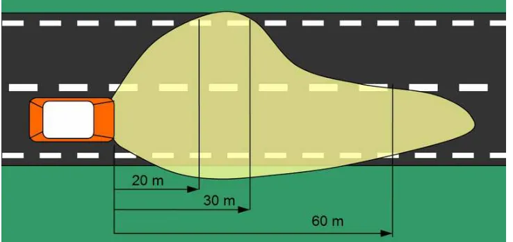
High beam (main beam, driving beam, full beam) headlamps provide a bright, centre-weighted distribution of light with no particular control of light directed towards other road users eyes. As such, they are only, suitable for use when alone on the road as the glare they produce will dazzle other drivers. International ECE regulations permit higher-intensity high-beam headlamps than are allowed under North American regulations.
Figure 2.3 European E-code high/Full beam