________________________________________________________________________________
A HUMAN BODY MODEL FOR DYNAMIC RESPONSE ANALYSIS OF AN
INTEGRATED HUMAN-SEAT-CONTROLLER-HIGH SPEED MARINE CRAFT
INTERACTION SYSTEM
T. Coe, J.T. Xing and R.A. Shenoi
The School of Engineering Sciences, Ship Science University of Southampton
Southampton, SO17 1BJ UK
Abstract
Small boats are increasingly being operated at high speed in rough weather by organisations carrying out essential missions such as the military and rescue services. Crew and passengers on these boats are exposed to continuous vibration and impacts leading to reduced crew effectiveness, fatigue and the possibility of injury. In addition to this marine craft will soon fall under the jurisdiction of the European Union Directive 2002/44/EC on the protection of workers from vibration.
To assess the possibility of injury and mitigate it at the design stage of a vessel a design tool is needed to assess the vibration levels on / in the human body while the boat operates in dynamic environments. A review of current human body models is presented and a new human body model, which allows for estimates of muscle activity, is proposed. This model is supplemented by a numerical approach using finite element methods to assess the dynamic response of the integrated human – seat - controller - boat interaction system excited by wave loads or boat motions measured in full scale boat operation tests. The vibration control actuators are arranged between the seat and boat to reduce vibrations transmitted to the human body from the boat to obtain a comfortable ride condition.
1. Introduction
In recent years the problem of vibration exposure at sea has become substantially more important.
There are two reasons for this, in many areas of the marine industry the use of high speed craft has
increased; secondly, the impending European legislation on vibration at work (European Union
Directive 2002) requires all boat operators to address the issue. The problem of vibrations at sea is
complex, rough sea produces large amplitude motions in all six degrees of freedom (Lloyd 1998). The
accelerations experienced by a small craft in rough seas can be severe. D’Arcy et al (2006) show
accelerations of up to eight g ( 78.48 ms-s) in moderate conditions. Ullman (2006) suggests values of
25 g (245.45 ms-2) and mentioned that the most significant vibrations are not only in the vertical
direction but also in lateral directions. When compared with vibration levels experienced in
automobiles, agricultural machinery and most industrial settings these values are very high and
complex, furthermore the European Directive on vibration exposure at work, Directive 2002/44/EC
(European Union Directive 2002) will apply to all vessels by 2010 and sets vibration exposure limits.
The ultimate solution to excessive vibrations and impacts generated by rough weather is either to
operators. Military and rescue operators may not have these two options available as missions may be
time critical. In addition to this, crew of these vessels must often perform vital tasks after long rough
transits. Evidence suggests that not only is there a high risk of injury (Ullman 2006) but also, reduced
performance after a long transit on a high speed vessel. For many years the vessel’s strength and
performance were limiting factors, now it seems that human frailty is a significant limiter.
In order to assess a vessel from the point of view of human vibration, be it either an existing design or
a new design, design tools are necessary to allow the vessel to be assessed easily, quickly and
cheaply. The concept proposed in this paper is that of a global numerical model to model the
integrated boat-seat-human interaction system. This model will allow the total system to be simulated
and the parameters of any vibration isolation device to be optimised.
2. Literature Review on Human Models
In order to maximise the usefulness of the global model it is necessary to develop a detailed model of
the human body. Simple models have been developed for many years to emulate the seat to head
transmissibility or apparent mass of the human body, such as that developed by Suggs et al (1969),
shown in Figure 1. This simple approach is not sufficient to assess the potential for injury. To that
end advanced human body models were considered, those detailed below represent the state of the
art in the human body modelling field. Detailed modelling of the human spine allows estimations of the
spinal loads to be carried out.
Pankoke et al (1998) developed an advanced model of a sitting man using Finite Element Modelling
(FEM) techniques. The model focuses its detail on the lumbar spine region modelling the individual
vertebrae and including the muscles of the lower back region as multiple springs. In order to reduce
computational time the rest of the model is represented by rigid bodies with mass. The model was
developed with three different postures, upright, relaxed (lorry driver) and slumped forward (crane
operator). The model is also easily adjusted in both weight and height. The overall motion of the body
model has been validated against experimental data and shows very good agreement with test data at
frequencies up to about 7 Hz. Pankoke et al use the model to predict forces in the lumbar region of the
[image:3.595.208.388.259.453.2]spine.
Figure 2 The FEA Model developed by Pankoke et al (1998)
Seidel et al(2001) used the finite element model developed by Pankoke et al (1998) to predict the
loads in the spine during whole body vibration. They carried out further validation of the model against
experimental data and a different model. The comparison shows that the model and the assumptions
based it is based on are valid. As with other work on this type of model it is impossible to validate the
internal forces within the spine.
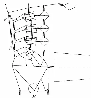
Pankoke et al (2001) modified a highly detailed FEA model, similar to the model by Pankoke et al
(1998) to produce a simpler model for force prediction in the lumbar region of the spine. The model
represents vertebrae as rigid bodies connected by springs representing the inter-vertebrae disks.
Muscles in the lumbar region of the spine are also represented by springs. As part of the simplification
process the model properties have also been linearised to reduce the overall complexity. The model
differs from Pankoke et al (1998) being three dimensional and representing the lumbar muscular
As with other spinal force prediction methods, it is impossible to directly verify the results of the model,
however excellent results were obtained when using non-invasive methods. The model is only applied
to vertical accelerations however unlike the majority of other models it is three dimensional and
[image:4.595.142.454.175.369.2]therefore could potentially be used for the six degree of freedom marine case.
Figure 3 Pankoke et al(2001) reduced model representation of the lumbar spine
Figure 4 Complete Pankoke reduced model
Verver et al (2003) developed a model using numerical methods. Individual vertebrae are modelled as
rigid bodies and are connected with joints, “in which translational and rotational stiffnesses are
implemented” (Verver et al. 2003) The model is based on the MADYMO crash simulation model and
includes the outer surface of the body modelled as a finite element mesh, connected to the internal
[image:4.595.194.397.406.616.2]this model achieved mixed results. When testing using a rigid seat, results for transmissibility to the
head, first Vertebrae and Pelvis (Verver et al. 2003) compared poorly with experimental data from
several subjects. Both magnitude and shape of the transfer function bear only tenuous resemblance to
the experimental data. However when testing on a standard car seat, results where much improved.
The model correctly predicts the seat to head resonance peak at about 3.5 Hz and while the predicted
amplitude of motions is rather high this is in common with several other models, notably (Boileau and
Rakheja 1998). The nature of the model allows axial and shear forces for the spine to be calculated.
These data can be considered with some confidence due to the transmissibility results. The ability to
measure intra-body forces is useful in minimizing fatigue in the human body. The model is unique in its
use of a three dimensional geometry incorporating the outer surface of the body however some of the
comparisons with experimental data are poor.
Figure.5 Spinal Shear Force Model by Verver et al (2003)
Having considered the current human body models it was decided to utilize an approach similar to that
of Pankoke et al (1998) for our own biomechanical model. As stressed above, in the marine
environment the experienced vibrations occur in all six degrees of freedom with no one degree being
dominant therefore it is necessary to develop a six degree of freedom model.
3. An improved model
The new human body model proposed here is intended to allow the vibration seriousness to be
assessed and vibration isolation seating to be designed. Compared to previous models, this model
has the following features. A key feature, as mentioned above is detailed representation of the lumbar
back, it is possible to estimate the forces applied to the back and assess their severity and the
effectiveness of vibration isolation.
• Three dimensional capabilities. The new model is a complete, three dimensional
representation of the seated human being. This allows the complex six degree-of-freedom
problem of a small boat at sea to be addressed.
• Modular capability. The modelling approach allows various aspects of the model to be
improved over time. As shown in Figure 6, modelling has been concentrated in the lumbar
spine area but the approach used allows the other areas to be updated and become
increasingly detailed as work continues.
At present the human body has been divided into 4 distinct areas similar to those used by Pankoke et
al (1998) and shown in Figure 6. For the initial global model, detailed modelling is restricted to region
C the lumbar spine area.
Figure 6 The four development regions of the human body
It is necessary to include a high level of detail in the lumbar region of the body and this is the prime
focus of model development. Lumbar vertebrae are taken from the ANSYS Model developed by
Grunendahl (2003) at Aachen University and simplified by removal of the cartilage of the
Figure 7 lumbar spine vertebrae
Regions A and B have been developed in simplified form from the NASA Anthropometry guidelines for
a 50th percentile man, the pelvis geometry has been simplified from a freely available IGES file from
3D Doctor (3D Doctor 2006) to produce a simple body.
The key to this research is the detailed representation of the muscles of the lumbar spine, muscle
position is taken from standard texts on human anatomy (Bloomfield et al. 1994; Marieb 2004). The
muscles are modelled as linear springs, a method that has been used successfully by Pankoke et al
(1998; 2001) and others(Prasad and King 1974; Belytschko and Privitzer 1983). Differing properties
are used for different areas of muscle allowing the muscle properties to be easily adjusted.
[image:7.595.119.477.419.717.2]Figure 8 clearly shows the deepest muscles of the spine, these are modelled at the level of the
individual vertebrae. The lumbar region is then developed, incorporating additional levels of muscular
[image:8.595.130.467.109.405.2]structure. This structure is partly shown in Figure 9. (some additional muscles removed for clarity)
Figure 9 Multifidus and Illiocostalis lumborum representations
The model will allow the input of forces or displacements at the pelvis and output of motions of the
head or chest and displacements, accelerations and forces on the lumbar spine. For this type of model
it is notoriously difficult to obtain stiffness parameters for the materials used. For this model it is
proposed that a combination of two techniques is used to identify mass, stiffness and damping
parameters. The first is to utilize the published values and ranges to place the parameters within
acceptable limits, having carried this out, published seat to head transmissibility data and apparent
mass data can be used optimize the parameters.
4. Integrated modelling
The new human model discussed above takes its place as part of an integrated model. The aim of the
modelling process is to create a model which can be used to optimise suspension seat parameters.
This model will be a global, numerical model incorporating the vessel, seat and the human as shown
in Figure 10. The input to this model is the six degree of freedom motion generated by the force of the
sea on a vessel, the model then considers the interaction between the boat and the seat and the seat
and the human. The model will then allow a designer or surveyor to input a vessel design and assess
its vibration performance, results can then be used to develop suitable isolation systems for that
Figure 10 Model concept
In the final system the boat hull geometry will be added by the designer or surveyor of the particular
hull. For the purposes of this model the hull is based on the geometry of an Atlantic 21 RNLI Lifeboat
hullform, modelled in ANSYS from a DXF linesplan and automatically meshed using ANSYS. The
Atlantic is typical of the type of vessel that this model will be used for and performance data are
available for various aspects of the craft. Figure 11 shows the meshed model, generated using shell
elements and a coarse level of detail. It is intended to model the vessel’s structure more accurately,
including plating and stiffeners to better represent the vibration behaviour of the boat.
Figure 11 ANSYS Meshed Model of Atlantic 21
The vibration isolation seat will be inserted into this model between the vessel and the human body.
Different types of seat can be inserted for different conditions.
This integrated model will allow the comparison of seat designs for a given boat and will allow the seat
stiffness and damping parameters of a suspension seat can be seen and seats can be judged on
various criteria.
5. Validation
Model validation will be carried out using full scale tests with high speed vessels. It is not possible to
measure forces within the bodies of the crew on these vessels, so as with the parameter identification
process validation will be based on easily measurable quantities such as seat to head transmissibility.
The difference between this and the parameter identification work is in the nature of the vibration
experienced. By comparing model results with those for the real, intended use of the model its
appropriateness for the task can be assessed. In addition to vibration measurements, crew heart rate
and Oxygen use will also be measured, hopefully allowing some correlation with lumbar spine load
data.
6. Conclusions
An improved human model incorporating into an integrated boat-controller-seat-human interaction
system is proposed in this paper. The proposed model will be used to calculate the vibration levels on
and in the human body transmitted from the boat excited by external forces from sea way. This three
dimensional integrated model, after a further numerically and experimentally investigation, may
provide a useful tool for assessing the performance of a vessel and its seat isolation system to allow
optimisation seat designs to be considered during the design phase of creating a new high speed craft
and to allow boat operators to better meet coming health and safety criteria.
7. References
3D Doctor (2006). 3D Doctor Example Pelvis, Abel Software Corp http://www.ablesw.com/3d-doctor/images.html.
Belytschko, T. B. and E. Privitzer (1983). A Three Dimensional Discreet Element Dynamic Model Of The Spine Head and Torso. AGARD Conference on Models And Analogues for the Evaluation of Human Biodynamic Responses AGARD.
Bloomfield, J., T. R. Ackland, et al. (1994). Applied Anatomy and Biomechanics in Sport. Victoria, Australia, Blackwell Scientific Publications.
Boileau, P. E. and S. Rakheja (1998). "Whole-body vertical biodynamic response characteristics of the seated vehicle driver: Measurement and model development." International Journal of Industrial Ergonomics 22(6): 449-472.
D'Arcy, T. R., I. R. House, et al. (2006). Design Procedure For A Record Breaking Craft From A Human Factors Perspective. Ship Science. Southampton University of Southampton. MEng. European Union Directive (2002). Directive 2002/44/EC of the European Parliment and of the council
of 25th June 2002 on the minimum health and safety requirments regarding the exposure of workers to the risks arising from physical agents (vibration) (Sixteenth individual Directive within the meaning of Article 16(1) of Directive 89/391/EEC, European Union.
Grunendahl, A. (2003). L4-Vertebra. F. t. B. R. http://www.tecno.ior.it/VRLAB/.
Lloyd, A. R. J. M. (1998). Seakeeping:Ship Behaviour in Rough Weather. Gosport, Lloyd, A.R.J.M. Marieb, E. N. (2004). Human Anatomy & Physiology San Francisco, Pearson Benjamin Cummings. Pankoke, S., B. Buck, et al. (1998). "DYNAMIC FE MODEL OF SITTING MAN ADJUSTABLE TO
Pankoke, S., J. Hofmann, et al. (2001). "Determination of vibration-related spinal loads by numerical simulation." Clinical Biomechanics 16(Supplement 1): S45-S56.
Prasad, P. and A. I. King (1974). "An experimentally validated biodynamic model of the spine." Transactions of the American Society of Mechanical Engineers: 546-550.
Seidel, H., R. Bluthner, et al. (2001). "Application of finite-element models to predict forces acting on the lumbar spine during whole-body vibration." Clinical Biomechanics 16(Supplement 1): S57-S63.
Suggs, C. W., Abrams,C.F. and Stikeleather, L.F. (1969). "Application of a damped spring-mass human vibration simulator in vibration testing of vehicle seats." Ergonomics 12(1): 79-90. Ullman, J. (2006). How can we cope with impact? Risks and injury mechanisms. What is fatigue? How
to maintain operative efficiency Shock mitigation technologies of today. SeaWork International High Speed Craft Seminar, Southampton.