Reusable Web Services
Peter Henderson and Jingtao Yang
University of Southampton, Southampton SO17 1BJ, UK
[email protected], [email protected],
WWW home page:http://www.ecs.soton.ac.uk/~ph
Abstract. Designing systems of asynchronous web services is challeng-ing. Addressing the design in terms of component reuse helps address important questions that need to be answered if dynamic configuration of business solutions from web services is to be achieved. The fact that the components are web services doesn’t mean that all the problems of reuse have been solved. An architecture for dealing with reuse and dy-namic reconfiguration, based on stateless services and stateful messages, is investigated. A notation for describing the flow of documents in such a system is introduced. This is shown to be effective at describing the behaviour of components, a necessary part of designing reusable com-ponents, especially those that participate in long-running, asynchronous interactions.
1
Introduction
Global systems built to support long running interactions have particular re-quirements when it comes to reuse of components. The contemporary view of how such systems should be built is to deploy web services and to engineer business processes to coordinate interactions among these services [3]. Long run-ning interactions are necessarily asynchronous [8] and asynchronous interactions among components have new challenges for component design, especially in the context of reuse [5], [7], [9].
When interactions run for long periods (days, weeks) and when many business sessions are interleaved, it is never going to be convenient to stop the entire system in order to replace a component. Components therefore need to be hot-swapped, without disrupting the interactions in which the retiring component is involved, allowing the new component to continue with that sequence while providing some improved behaviour [6]. Web Services is the technology of choice for building such dynamic systems.
2
Web Services
Let us distinguish between what we shall call low-level web services and high-level web services. We will use the term low-level web services when referring to the basic technologies provided by web servers enabled to support SOAP interactions and WSDL defined interfaces [1], [2]. These are the basic technologies available in Java Web Services and in .NET. The web service is published on a host, along with its WSDL interface description, in such a way that a subscriber can use the WSDL description to construct a stub for use in accessing the service. The subscriber might be using a quite different platform and technology than the web service publisher.
We will use the term high-level web services when referring to the way in which low-level web services are orchestrated to deliver business processes [3], [4]. Here we address the domain of high-level web services and discuss the types of architecture and of business solution that high-level web services engender.
ServiceProvider ServiceUser
Fig. 1.A basic client-server web service architecture. The arrow points from client to server.
ServiceProvider
ServiceUser
ServiceProvider Agent
ServiceUser
Fig. 2. An orchestrating web service, the Agent, makes use of two other web services.
Figure 1 shows the basic client-server structure of an elementary web service solution. The ServiceUser invokes the web service on the ServiceProvider and anticipates a result. The arrow in the diagram points from client to server. Requests will travel in the direction of the arrow and replies (if any) will travel in the opposite direction.
Figure 2 shows a slightly less trivial system. Here we have an orchestrating web service (called Agent here) that makes use of two other web services, coor-dinating or orchestrating their combined service. For example, the ServiceUser may make a query. That query goes to Agent which, let us say, makes enquiries of the two ServiceProviders that it is attached to and combines their replies in some way before returning that reply to the ServiceUser.
but for the reasons given earlier (that we are concerned primarily with very long running interactions) we will concentrate here on asynchronous interactions.
Recall that the arrows in these diagrams point from client to server. The Agent is a web service acting as a server to the ServiceUser and a client to the ServiceProviders. When many ServiceUsers are active each Agent and each Ser-viceProvider will see the messages comprising the interactions in an arbitrarily interleaved order. The reuse issues here are numerous. A new type of Agent or ServiceUser could be deployed and would need to interact with Agents and Servi-ceProviders that were in themiddle of their interactions with others. Moreover, a new ServiceProvider might be required to replace an existing ServiceProvider and have to be in a position to complete any of the interactions that the original ServiceProvider had started but not yet completed.
Figure 3shows how a single ServiceProvider from Figure 2 can be replaced by a coordinated network of (in this case) two other ServiceProviders. The as-sumption here is that the interfaces that the Agent implements are such that to a ServiceUser the Agent looks just like a ServiceProvider and to a Service-Provider the Agent looks just like a ServiceUser. Whilst such a neat arrangement of the interfaces seems to solve some of the reusability issues (for example, we know what type of interface plugs in where) it exacerbates other problems. In particular, when it comes to the behaviour of interactions across an interface, the ability to unplug one component and plug in an alternative is non-trivial, as we shall show.
ServiceUser
ServiceProvider Agent
ServiceProvider
ServiceProvider Agent
ServiceUser
Fig. 3. One ServiceProvider can be re-placed by a coordinated network of others
ServiceProvider
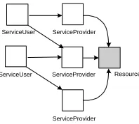
[image:3.612.165.323.350.450.2]ServiceUser Resource
Fig. 4. Making a Web Service stateless by sep-arating off the state into a, probably persistent, Resource [4]. Shaded boxes are statefulin these diagrams.
One aspect of our ability to simply unplug something in the middle of a long-running interaction and plug in an alternative, is whether or not the component has state. As in [4], [10], we will distinguish between components that have state and interactions that have state. In the diagrams so far we have used shading to indicate components that have state. We have assumed ServiceProviders are stateful and Agents and ServiceUsers are stateless. This is an arbitrary choice, to illustrate a point.
reasons that one of the principal design criteria for Web Services is that they should be stateless [11].
There are two distinct mechanisms for making Web Services stateless. The first is to separate the state into an independent (probably persistent) com-ponent, such as a database, leaving the functionality in a replaceable stateless component (see Figure 4). The second is to put the state in the interaction (using cookies, session objects etc), which is considerably more powerful than one might imagine, although it is not sufficient on its own. The next section addresses these issues explicitly.
A Web Service is in reality deployed in a container (Figure 5). One of the functions of the container is to decide whether a request is handled by an existing instance of a component or by a new instance. Another (orthogonal) decision is whether the container generates a new thread for each request. The assumption
ServiceProvider ServiceUser
[image:4.612.185.269.261.311.2]Container
Fig. 5. The container in which web services are deployed deter-mines properties of components. Usually the container is respon-sible for demultiplexing mes-sages and forwarding them, con-currently, to specific instances of components.
ServiceProvider ServiceUser Resource
ServiceProvider
[image:4.612.323.422.270.359.2]ServiceProvider ServiceUser
Fig. 6. Reusable Web Services with stateless components and statefulinteractions
we make is that components in the diagrams are instances and that the con-tainer will indeed use a new thread for each request. This means that requests can in fact overtake each other, which significantly complicates reasoning about asynchronous behaviour.
3
Document Flow Model
We have established the need to design asynchronous interactions among Web Services. In this section we introduce a design notation for reasoning about such interactions. We use this to show some of the consequences for reusability of components, when we are explicit about the behaviour in which they engage. In particular we address an important issue concerning the parallel delegation of work.
The design notation we are going to introduce is based on our experience with XML and its associated technologies. Because we concentrate on the se-quence in which messages are sent and the consese-quences for a component of receiving a message, and since for us messages are documents, we call the design notation Document Flow Model (DFM). We use DFM to design systems which are eventually realised using XML encoded documents.
Here is a document.
[to:s1, from:u, query:q]
It could be the message sent from the ServiceUser to the ServiceProvider in Figure 1. A document is an object (or a record) with named attributes, each of whose values is either an atom or a document.
The only other part of DFM is that we show the action performed by a service provider on receipt of a message. In an asynchronous world this usually comprises querying and updating local state (if any) and sending replies or, more generally, further messages. So, for example we can specify the behaviour of the ServiceProvider in Figure 1 by
onMessage [to:s1, from:u, query:q]
send [to:u, from:s1, reply:[query:q, result:r]]
Here we have used the incoming message as a pattern, where the values of the attributes are taken to be names for the relevant parts of the message. The re-sponse of the ServiceProvider is to construct a reply that is self-identifying by virtue of the fact that it contains sufficient details of the original query that the receiver will be able to re-establish its context. We assume the Service-Provider can compute the reply detail (r) from the query detail (q). By returning
[query:q, result:r] the ServiceUser doesn’t have to remember which query was
sent where and in what order they were sent. The replies can return in any order and still be processed. Putting the query in the reply is the simplest example of adding context (state) to an interaction.
Now let us look at the interactions that may take place in the system shown in Figure 2. Assume the ServiceUser sends the following document
[to:a, from:u, query:q, context:c]
It’s almost the same document as before, but this time sent to an Agent. This time the document carries an extra element, the context, whose purpose will soon become clear. The ServiceUser doesn’t care about whether they are talking to a ServiceProvider or an Agent.
onMessage [to:a, from:u, query:q, context:c] send [to:s1, from:a, query:q1,
context:[from:u, query:q, context:c]]
where we have assumedq1 is a part of the queryq, specifically to be addressed tos1. This is a request to a ServiceProvider in the format expected by the Ser-viceProvider, in the sense that it has all the attributes that the ServiceProvider expects (i.e. to, from and query). We are using the convention of XML that extra elements in a message are acceptable. In this case, we are going to use them. But sometimes we will just ignore them.
The response from the ServiceProvider is
onMessage [to:s1, from:a, query:q1, context:c]
send [to:a, from:s1, reply:[query:q1, result:r1], context:c]
Again, we see that the reply is in the form that a ServiceProvider normally sends to a ServiceUser, but carrying extra state in the context component. The design of these documents is entirely at the discretion of the designer of the interaction. There is nothing special about any of the attributes (except that we assume the messaging system makes use of theto field)
Next, the Agent sends the query on to the second ServiceProvider
onMessage [to:a, from:s1, reply:[query:q1, result:r1], context:[from:u, query:q, context:c]] send [to:s2, from:a, query:q2,
context:[from:u, query:q, context:c,
reply:[query:q1, result:r1]]]
again, assumingq2 is a subquery of q. And so it goes on. The second Service-Provider replies
onMessage [to:s2, from:a, query:q2, context:c]
send [to:a, from:s2, reply:[query:q2, result:r2], context:c]
and so eventually, the Agent can complete the interaction
onMessage [to:a, from:s2, reply:[query:q2, result:r2], context:[from:u, query:q, context:c,
reply:[query:q1, result:r1]]]] send [to:u, from:a, reply:[query:q, result:[r1,r2]],
context:[from:u, query:q, context:c]]
This sequence of document exchanges, where we have assumed the Agent’s task is to consult both ServiceProviders, is a sequential solution. The two Service-Providers are consulted in sequence. The ServiceService-Providers actually respond to the queries they receive in exactly the same way, notwithstanding the different details we have given above. They compute their reply to the query (using local state, if necessary) and return their reply along with the context they received, no matter how complex that context is.
build networks of Agents that work together to process complex queries. This requirement manifests itself in the way that the Agent constructs its reply toq2.
It returns the reply along with the context of that reply. The context is needed in the case that the reply is being returned to another Agent.
The Agent responds to the documents it receives in a stateless way. It uses the information in the document to demultiplex the messages it receives. So it can tell from the second reply that the entire query has been resolved and that it must reply to the user.
But if it had sent the two queries off to the two ServiceProviders concurrently, putting the context in the message wouldn’t suffice. The Agent would need to remember the first reply until it got the second. The Agent would need to be stateful. This is the problem we will solve in the next section.
4
Contexts and Coordination
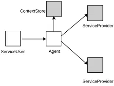
We introduce the notion of a Context Store in which we will store contexts (see Figure 7). Each context will be stored under a unique identifier (uid) and this identifier passed between services as a means of coordination. A Web Service can have its own unique Context Store, or it can share a Context Store with someone else. In general, shared Context Stores will be used to maintain the statelessness of the Web Service. Rather than reprogram the sequential solution to make use of this concept, we shall program a parallel solution.
onMessage [to:a, from:u, query:q, context:c] generate new uid
store uid -> [from:u, query:q, context:c] in CS send [to:s1, from:a, query:q1, context:uid] send [to:s2, from:a, query:q2, context:uid]
onMessage [to:si, from:a, query:qi, context:uid]
send [to:a, from:si, reply:[query:qi, result:ri], context:uid]
onMessage [to:a, from:si, reply:[query:qi, result:ri], context:uid] store uid -> [query:qi, result:ri] in CS
if CS[uid] contains [from:u, query:q, context:c],
[query:q1, result:r1] and [query:q2, result:r2] then send [to:u, from:a,
reply:[query:q, result:[r1,r2]], context:c]
ServiceProvider
ServiceUser
ServiceProvider Agent
[image:8.612.249.366.65.153.2]ContextStore
Fig. 7.Making use of a Context Store to give an Agent some state
cooperative enough to return the uid with the reply. Each time we get a reply, we look to see if we now have enough information to complete the Agent’s task. This will happen of course when the second reply arrives. But this structure obviously generalises to more than two ServiceProviders. When enough information has been gathered, the Agent replies to the user, as before.
Thus we see that the combination of a Context Store and stateful interactions, where the state in the message is simply a uid, is sufficient to solve the problem of parallelising the interaction. This is a conventional solution to the problem that we have captured succinctly in the DFM notation.
But there is another valuable consequence of this design, important for dy-namic deployment and for component reuse. This is that the multiple-instances of a Web Service around a shared resource that we showed in Figure 6 actually generalises to multiple instances of an Agent. For the case of a sequential Agent, this is shown in Figure 8.
ServiceProvider
ServiceUser
ServiceProvider Agent
ContextStore
Agent
[image:8.612.162.445.386.559.2]Agent
Fig. 8. Document Flow to dif-ferent instances of a sequential Agent
ServiceProvider
ServiceUser
ServiceProvider Agent
ContextStore
Agent
Agent
Fig. 9.Document Flow to sep-arate instances of a parallel Agent
in the message. The dotted lines in this diagram show messages. One solid line is replaced by two dotted lines when the reply comes from or goes to a different instance than the request.
Figure 9 shows the document flow in the case of a parallel Agent. This time, either one of the Agents that receives a reply from the ServiceProvider could be the one that realises the query is complete and hence replies to the user.
5
Discussion
Web Services are intended to be reusable. That is the whole idea. A Web Service is a bit of business logic published on the web for anyone (or any authorised one) to use. Its interface is published as syntax and its behaviour is described as a document-transformer. By providing the means for dynamic binding of Web Services to application code, this technology goes a long way towards realising the dreams of reusable components that we have had for a long time in software engineering.
But it is not without its own problems. We want the systems built from Web Services to remain loosely-coupled, so that unplugging a component and plugging in another is not disruptive of a long running interaction. It should be the case, in a system of reusable components that, taking a component out degrades rather than damages or stops the system [6]. It should certainly be the case that putting the same component back into the same slot means that everything continues as normal, the only effect having been the inevitable delay. So here we have the potential for extreme reuse: box of components all of which can be plugged into that vacant slot, either providing different functionality, or the same functionality in different ways.
We have shown that a simple service can be replaced by a more complex one (Figure 3). We have shown that many instances of a Web Service can be substituted for a single instance (Figure 6). We have shown that a sequential service can be replaced by a parallel one (Figure 9). And we have, by these constructions, shown that a mixture of multiple instances, sequential and parallel services can be mixed and matched in a straightforward plug-and-play way.
The DFM notation has enabled us to make these claims explicit. The models shown here have been validated by building actual implementations using SOAP messaging and by testing these implementations extensively. We have shown that the components designed here are indeed reusable in all the contexts in which we have shown them. We are in the process now of extending this validation to include complete (finite) state space search, a process enabled by the formality of the DFM notation.
6
Conclusions
of business solutions from web services is to be achieved. We have defined an architecture for dealing with reuse and dynamic reconfiguration, based on state-less services and stateful messages. We have defined a notation for describing the flow of documents in such a system. We have shown that this notation is effective at describing the behaviour of components, a necessary part of making components that are reusable by others. The fact that our components are web services didn’t mean that all the problems of reuse had been solved. We exposed some of them using a formal document flow notation and showed that some conventional solutions to these ploblems, specifically a Context and a Context Store, are indeed effective.
References
1. Christensen E et al, Web Services Description Language (WSDL) 1.1, http://www.w3.org/TR/wsdl(2001)
2. Chinnici, R et al, , Web Services Description Language (WSDL) 2.0, http://www.w3.org/TR/2003/WD-wsdl20-20031110/ (2003)
3. Ferguson, D, B Lovering, Tony Storey and John Shewchuk, Secure, Reli-able, Transacted Web Services: Architecture and Composition, http://www-106.ibm.com/developerworks/webservices/library/ws-securtrans/ (2003)
4. Foster, Ian and 10 others, Modeling Stateful Resources with Web Ser-vices, http://www-106.ibm.com/developerworks/library/ws-resource/ws-modelingresources.pdf
5. Gomaa, Hassan, DanielA. Menasc, MichaelE. Shin. Reusable component intercon-nection patterns for distributed software architectures, Proceedings of Symposium on Software Reusability (SSR ’01)., ACM Software Engineering Notes, Volume 26, No 3, 2001
6. Henderson, Peter. Laws for Dynamic Systems, InternationalConference on Software Re-Use (ICSR 98), IEEE Computer Society Press, available at http://www.ecs.soton.ac.uk/˜ph/papers
7. Henderson, Peter. Asset Mapping - developing inter-enterprise solutions from legacy components, Systems Engineering for Business Process Change - New Directions, Springer-Verlag UK, pp 1-12, 2002
8. Henderson, Peter, Reasoning about Asynchronous Systems, Proceedings of the 18th InternationalConference on Engineering Complex Computer Systems (ICECCS 2002), IEEE Computer Society
9. Jahnke, Jens H.. Engineering component-based net-centric systems for embed-ded applications, Proceedings of the 8th European Software Engineering Confer-ence,ACM Software Engineering Notes, Volume 26, Issue 5, 2001
10. Parastatidis, Savas, Jim Webber, PaulWatson and Thomas Rischbeck, A Grid Application Framework based on Web Services Specifications and Practices, http://www.neresc.ac.uk/projects/gaf/, 2003
![Fig. 4. Making a WebService stateless by sep-arating off the state intoa,probablypersistent,Resource[4].Shadedboxesarestatefulinthese diagrams.](https://thumb-us.123doks.com/thumbv2/123dok_us/8518167.352224/3.612.165.323.350.450/making-webservice-stateless-arating-probablypersistent-resource-shadedboxesarestatefulinthese-diagrams.webp)