White Rose Research Online URL for this paper:
http://eprints.whiterose.ac.uk/101024/
Version: Accepted Version
Article:
Teachasrisaksakul, K, Zhang, Z-Q orcid.org/0000-0003-0204-3867, Yang, G-Z et al. (1
more author) (2015) Imitation of dynamic walking with BSN for humanoid robot. IEEE
Journal of Biomedical and Health Informatics, 19 (3). pp. 794-802. ISSN 2168-2194
https://doi.org/10.1109/JBHI.2015.2425221
© 2015 IEEE. This is an author produced version of a paper published in IEEE Journal of
Biomedical and Health Informatics. Personal use of this material is permitted. Permission
from IEEE must be obtained for all other uses, in any current or future media, including
reprinting/republishing this material for advertising or promotional purposes, creating new
collective works, for resale or redistribution to servers or lists, or reuse of any copyrighted
component of this work in other works. Uploaded in accordance with the publisher's
self-archiving policy.
[email protected] https://eprints.whiterose.ac.uk/
Reuse
Items deposited in White Rose Research Online are protected by copyright, with all rights reserved unless indicated otherwise. They may be downloaded and/or printed for private study, or other acts as permitted by national copyright laws. The publisher or other rights holders may allow further reproduction and re-use of the full text version. This is indicated by the licence information on the White Rose Research Online record for the item.
Takedown
If you consider content in White Rose Research Online to be in breach of UK law, please notify us by
Abstract— Humanoid robots have been used in a wide range of applications including entertainment, healthcare, and assistive living. In these applications, the robots are expected to perform a range of natural body motions, which can be either pre-programmed or learnt from human demonstration. This paper proposes a strategy for imitating dynamic walking gait for a humanoid robot by formulating the problem as an optimization process. The human motion data is recorded with an inertial sensor based motion tracking system (Biomotion+). Joint angle trajectories are obtained from the transformation of the estimated posture. Key locomotion frames corresponding to gait events are chosen from the trajectories. Due to differences in joint structures of the human and robot, the joint angles at these frames need to be optimized to satisfy the physical constraints of the robot whilst preserving robot stability. Interpolation among the optimized angles is needed to generate continuous angle trajectories. The method is validated using a NAO humanoid robot, with results demonstrating the effectiveness of the proposed strategy for dynamic walking.
Index Terms—Balance Control, Body Sensor Network, Dynamic Walking, Human Motion Imitation, Humanoid Robot, Wearable Sensors.
I. INTRODUCTION
UMANOID robots have been used in a wide range of applications that require human-robot interaction including entertainment [1, 2, 3], healthcare [4, 5], and assistive living [6]. They have also been used for assisting children with learning difficulties [7] to encourage social interaction [8, 9] and provide verbal and/or physical encouragement [10]. One of the challenges for such applications is how to make the humanoid robots perform different human movements naturally. In practice, the imitation of upper limb movement is relatively simple, since robot stability is easy to control if light weight arms are used [11]. For whole body movements, however, motion imitation is more challenging. Dynamic walking, for example, is difficult for the humanoids to imitate, as existing robots lack a
human’s complex set of autonomic sensorimotor balance and control.
Thus far, human walking reproduction on humanoid robots has been mainly conducted through motion generation. For
The authors are with the Hamlyn Centre, Imperial College London, London, SW7 2AZ United Kingdom (e-mail: {kt1312, z.zhang, benny.lo, g.z.yang}@imperial.ac.uk). Preliminary results of this paper were presented at BSN 2014, Zurich, Switzerland.
example, Gouaillier et al.[12] generated an omni-directional walking motion for NAO robot based on a preview controller. Massah et al.[13] introduced a method for planning the robot’s walking on slopes. Czarnetski et al.[14] controlled NAO
robot’s walking by using the preview controller and closed
loop control with sensor feedback. Li et al.[15] generated walking patterns for COMAN, a compliant humanoid robot, by controlling the center of mass. However, these methods
involve computation of joint trajectories for robot’s motion by
imposing stability constraints, but the resulting movement may not be natural or human-like because not all degrees of freedom (DOFs) are used. Furthermore, generating sophisticated motion sequences is challenging due to the large number of DOFs involved.
To overcome these problems, motion imitation, which employs human motion capture to acquire motion data and joint angle trajectories directly, has been explored recently. However, one-to-one direct mapping of joint angle of a human to a humanoid robot is not practical because of significant differences in joint configurations between human and a humanoid robot. Moreover, instability and motion beyond the physical capability of the robot need to be considered when a humanoid performs the mapped motion. Desirable robot motion must have intrinsic resemblance to human movement while maintaining the balance of the robot and respecting its mechanical constraints. To this end, several solutions have been proposed. For instance, gesture replication by Gaertner et al.[16] employed non-linear optimization to satisfy mechanical limits of the robot and desired hand positions and maximize angular similarity between human and a robot. Pollard et al.[17] scaled each joint’s angular trajectory locally in order to satisfy joint limits of the robot. Ott et al.[18] achieved motion imitation by using Cartesian tracking. In this method, a set of control points on the humanoid robot were virtually linked to measured marker positions on a subject’s body via springs. Dariush et al.[19] enabled upper-body motion replication by a humanoid robot by tracking motion descriptors defined in Cartesian space while fulfilling the required constraints. Suleiman et al.[20] represented mechanical limits by minimizing differences in joint angles of human and robot based on recursive dynamics. Jingru et al.[21] converted human motion into a robot’s motion through minimization of time and angular differences between trajectories of a human subject and a robot. All of the above methods dealt with only upper body movements, and they did not consider robot stability due to the exclusion of lower body
Imitation of Dynamic Walking with BSN for a
Humanoid Robot
Krittameth Teachasrisaksakul, Zhiqiang Zhang, Benny Lo, and Guang-Zhong Yang
movements.
For imitation of full body human motion, the main focus of existing methods is on balance maintenance. Two stability criteria which are used in these studies include Zero Moment Point (ZMP) [22] and Center of Mass (CoM). The general pipeline of balance maintenance involves designing ZMP trajectory for a humanoid robot, computing reference CoM trajectory from the ZMP trajectory, and constraining a humanoid robot to follow the reference CoM trajectory. Kim et al.[23] proposed a method for imitating full body dance movements. The ZMP trajectory of the robot was generated based on the support region and used to compute reference CoM trajectory by recursive equations. Under this scheme, the
robot’s pelvis was forced to follow the reference CoM to maintain balance. Hu et al.[24] used human walking data to
allow walking replication by a humanoid robot. The robot’s
ZMP trajectory was designed by projecting pelvis position according to support area then reference CoM trajectory was obtained by a preview controller. Closed loop inverse kinematics was applied to follow human end-effector positions. Koenemann and Bennewitz [25] performed whole body motion imitation by finding valid foot positions and applying inverse kinematics to compute lower body joint angles. However, the method was validated by using results from standing on one leg motion, not walking motion. It considered only static stability, not dynamic stability. Boutin et al.[26] imitated human walking. The ZMP trajectory of the robot was derived based on foot trajectories; and the CoM trajectory was also generated by a preview controller. The optimization algorithm for inverse kinematics was employed to find the joint angles that satisfy constraints on the swing foot and the reference CoM. However, these methods are all based on optical motion tracking, such as BTS [27] and Vicon [28]. Despite the highly accurate results they can provide, the use of optical tracking involves expensive cost and complex installation, limiting them to laboratory environment only. In addition, the use of optical motion data complicates the process of motion imitation because marker locations acquired from the optical motion tracker has to be scaled to fit to a humanoid robot before transformed into joint angles by inverse kinematics [29, 30]. Furthermore, all of these approaches require complex computations of the stability criteria and consideration of all motion frames in order to generate robot motion, which involves extensive computation load in practice. To this end, several methods which performed optimization to minimize error between movements of human and a humanoid robot and interpolation between discrete time points have been proposed [16, 19, 20, 21]. For example, Kim et al.[23] optimized joint angle trajectories to minimize error between movements of human and a humanoid robot; then applied spline interpolation to smooth angle trajectories of upper body. Boutin et al.[26] formulated inverse kinematics as an optimization problem to find joint angles for walking that satisfy motion constraints. However, these methods applied optimization and interpolation to upper body joint angles only.
In this paper, we applied wearable inertial sensor-based
systems to acquire human motion, which can offer a similar tracking accuracy of optical system, but overcomes the limitation on cost and usability. We further extends our initial results reported in [11], and focus on dynamic walking motion production by performing optimization and interpolation to lower body joint angles. The main contribution of this paper includes: 1) the task of dynamic walking imitation is deemed an optimization process that seeks for joint configurations. Owing to inconsistencies in the joint structures of human and a humanoid robot, a cost function for minimizing angular differences between human trajectories and robot trajectories is proposed; 2) To maintain the robot balance during dynamic waking, the centre of mass (CoM) can be outside the support area for a short duration rather than keeping its projection inside the foot support area throughout the motion. A novel and simple CoM trajectory scheme is thus designed to make the robot walking imitation dynamically stable; 3) To simplify replication of walking, key motion frames in a gait cycle are selected and the proposed optimization approach is applied to these key frames only. Interpolation among the key frames is then employed to generate continuous angle trajectories. The method is validated using a NAO humanoid robot, with results demonstrating the effectiveness of the proposed strategy for walking imitation.
Fig. 1. Kinematic representation of the joints of a humanoid robot NAO H25
II. DYNAMIC WALKING IMITATION METHOD
A. Biomotion+ and NAO Robot
of NAO H25 is illustrated in Fig. 1. More specifically, the neck of the robot has 2 DOFs. Each arm has 5 DOFs: 2 DOFs, 2 DOFs, and 1 DOF at the shoulder, elbow, and wrist, respectively. Each leg has 5 DOFs: 2 DOFs, 1 DOF, and 2 DOFs at the hip, knee, and ankle, respectively. The NAO robot contains a total of 23 DOFs and the kinematic model of the robot, however, contains 22 DOFs due to the exclusion of Hip Yaw Pitch joint axis [34].
B. Generation of Joint Angle Trajectory
For the Biomotion+ platform, quaternion with respect to the global reference frame is used to represent orientations of the segments, which are converted into joint angles. The conversion of the orientations into joint angles requires orientation difference between any two adjacent body segments.
Given any two quaternion and , the orientation difference from to is defined as:
(1)
where is the quaternion multiplication [35]. The conversion of orientation difference into the rotational angles requires the Direction Cosine Matrix (DCM) representation :
(2)
where and are the vector and the scalar component of the quaternion , and is an operator for cross product. The transformation of the rotation matrix into Euler angles is specific to each joint. The angles of shoulder, elbow, hip, and knee joints can be computed from the motion capture data. The rotation sequence for computing the angles of shoulder, hip, and knee is XZY. The sequence XZY defines rotations of a rotating reference frame about its Z-axis, Y-axis, and X-axis, respectively. Shoulder Pitch and Shoulder Roll, axes of a shoulder joint, are set to align with the X and Z axes of the reference frame. Hip Pitch and Hip Roll, axes of a hip joint, align with the X and Z axes. Knee Pitch of a knee joint aligns with the X axis. Additionally, YZX and YZY are the rotation sequences for computing elbow angles. To acquire the angles of Elbow Yaw and Elbow Roll joint axes, Y-axis angle of YZX and Z-axis angle of YZY are computed.
C. Walking Motion Imitation
1) Formulation of Walking Imitation Task as an Optimization Problem
The task of motion imitation is deemed an optimization process that seeks for joint configurations. Maintaining resemblance between robot motion and human motion is the key objective of motion imitation. Therefore, the estimations of robot joint angles vector at time should satisfy:
argmin (3)
where
(4)
and and are the humanoid robot’s and a human
demonstrator’s joint angle configurations at time ,
respectively. Several constraints, including mechanical constraint and stability constraints should be satisfied as well during the optimization process. The required constraints are shown in Fig. 2. In the rest of this section, we will explain these constraints in detail.
[image:4.612.318.559.113.241.2]Fig. 2. The constraints of the humanoid robot required in the proposed framework for human walking imitation.
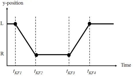
Fig. 3. The development of reference CoM position in y-axis. The four dots represent reference CoM positions in y-axis at the four key locomotion frames. L is left foot and R is right foot.
2) Balance Constraint
[image:4.612.323.555.276.408.2]transition of the CoM. Heel strike is selected as a frame boundary because it represents the beginning of the left foot support or right foot support. The derivation of the y-axis of reference CoM point is shown in Fig. 3. Because and are the moment prior to right heel strike and left heel strike, respectively, is transferred from the left to the right foot during the period between and ; and vice versa during the period between and . Thus, the y-axis of reference CoM point can be written as:
if
if
if
if
(5)
where and are the y-coordinates of the center of the left foot and the right foot, respectively, at time . is the first key frame of the next gait cycle. According to Fig. 4, and are taken as the time points when maximum right and left hip flexion angles exist. These are the time points after the swing phase and before a heel-strike event. The mid-swing phase is characterized by positive peak of shank angular velocity [36]. and are detected from shank angular velocity. Terminal contact (TC) or toe-off event is characterized by a negative peak of shank angular velocity [36].
The reference CoM position of the x-axis is also chosen based on the four phases. For the left foot support or the right foot support phase, the reference CoM x-axis position can be taken as the support foot’s center:
(6)
where is the th corner position of the support foot at
time . As shown in Fig. 5, during the transition periods, can be written as:
if
if
(7)
where the center position of the left foot and the center
position of the right foot are defined as:
(8)
where is the th corner position of the left foot and
[image:5.612.326.550.62.306.2]is the th corner position of the right foot.
[image:5.612.334.539.398.537.2]Fig. 4. Criteria for selection of four key locomotion frames , , , . Left/Right hip flexion angles in degrees derived from the wearable inertial motion capture system (upper) and left/right shank angular velocity around x-axis in radians/second (lower) measured directly by the gyroscope in a gait cycle. The angles and angular velocity of left and right leg are represented by the normal lines and the dashed lines, respectively. The horizontal axes of both plots represent the frame index of motion. Heel strikes of left and right feet are represented by diamond-shaped points.
Fig. 5. The development of x-axis reference CoM position. The dots represent the reference CoM positions at the key locomotion frames. L is left foot and R is right foot.
In our implementation, we use the trunk or torso position as
the CoM since it contains the majority of the robot’s mass.
The actual torso position is computed by forward kinematics
of the robot:
Trans (9)
where Trans is an operator for obtaining the translational
part of a transformation matrix and is the forward kinematics function, which can be written as:
where is the index of a base frame, is the index of an end-effector frame , is a transformation matrix from the th link frame to the th link frame of the robot’s
kinematic model, and is the angle of the th joint. The stability constraint can thus be written as:
(11)
where is a small threshold.
3) Foot Constraints
To make the robot walk more stably, the swing foot should not be lower than the ground or lifted too high. Therefore, the height of the swing foot must satisfy:
(12)
where is the maximum swing foot height which is an empirically chosen parameter. It is based on the default value of the parameter used in the walking controller of the NAO robot [37]. Actual swing foot height can be computed by forward kinematics of a kinematic model of the robot:
Trans (13)
where is the robot’s joint angle configuration at time , and and are the base frame index and the swing foot frame
index of the robot’s model. According to Fig. 1, and are 1 and 5 for the left foot; and 6 and 10 for the right foot.
4) Mechanical Constraints
The joint angles of the robot have to be within its mechanical limits particularly the limits of joint angles. Thus,
must satisfy:
min max (14)
where min and max are minimal and maximal angle configurations of the robot’s joint.
5) Artificial Constraints
In addition to mechanical constraints, several artificial constraints can also be considered to make the robot walk more naturally and improve balance maintenance. Since significant changes in KneePitch angles between two motion frames can pose an abrupt change in torso height and thus instability; therefore, KneePitch angle must satisfy:
(15)
where denote a desired KneePitch angle and denote a threshold for Knee Pitch angle error In the real implementation, and are set to 0.95 and 0.05 radians empirically. Furthermore, to limit the robot’s body sway motion, the torso is controlled to align with the global frame; thus an actual orientation of the torso must satisfy:
(16)
where is a threshold for orientation error of the torso and is an actual torso orientation that can be computed by forward kinematics:
Rot (17)
where Rot is an operator for obtaining the rotational part of a transformation matrix. Forcing the alignment of the swing foot with the ground plane is also considered to prevent
stumbling of the robot. Thus, the swing foot’s real orientation
must satisfy:
(18)
where is a threshold for orientation deviation of the swing foot. Real orientation of the swing foot can be computed by forward kinematics:
Rot (19)
Finally, the Sequential Quadratic Programming (SQP) can be applied to solve the formulated optimization problem with non-linear cost function and constraints for each frame separately [38, 39]. For the ease computation, only the four key frames are sent to the proposed optimization framework to
obtain the robot’s optimal joint configurations at these frames.
Interpolation based on Piecewise Cubic Hermite Interpolating Polynomial (PCHIP) [40] is applied to the joint configurations in order to obtain intermediate joint angles among these frames and to complete a gait cycle of the robot.
TABLEI
THE SPECIFIED VALUES OF THE CONSTRAINTS
Threshold The values of the constraints (m) [5x10⁻³ 5x10⁻³ 5x10⁻³]T
(degree) [2 0.5 4]T
(m) [1x10⁻² 1x10⁻³ 3x10⁻²]T
(degree) [13 3 10]T
TABLEII
MEAN AND STANDARD DEVIATION OF ANGULAR ERRORS (IN DEGREES) OF
HUMAN JOINT ANGLES AND OPTIMIZED ANGLES OF THE ROBOT’S JOINTS IN
WALKING MOTION
Joints Mean SD
Left hip roll 4.0682 4.4602 Left hip pitch 6.1685 3.6835 Left knee pitch 13.3663 6.9338 Right hip roll 3.6242 4.4084 Right hip pitch 7.8396 5.7270 Right knee pitch 7.1109 2.1900
III. EXPERIMENTAL RESULTS AND DISCUSSIONS
A. Experimental Setup
Human walking was used for validating the proposed framework for motion imitation. To produce robot motion, the proposed framework was employed to adapt the captured human motion data by using the constraints listed in TABLE I.
B. Experimental Results
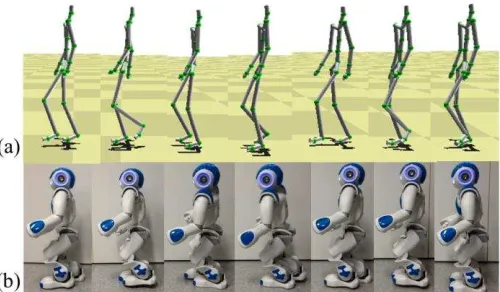
To examine whether the humanoid robot is able to perform the generated movement, the optimized joint angles were transmitted to NAO robot for joint rotations. The successful imitation of human gait by the robot is illustrated in Fig. 6(b). The robot was able to perform similar postures compared to human and follow three gait cycles in the sagittal plane by executing repetitions of the generated movement. Moreover, the balance of the robot was maintained throughout the period of motion.
Fig. 7(b) shows the imitation results of walking data captured with Vicon, the optical motion capture platform, which is the
Fig. 6. (a) Human walking gait acquired from the Biomotion+ platform and (b) the robot walking reproduced from the Biomotion+ data.
dataset of subject 7 (trial 2) from Carnegie Mellon University (CMU) motion capture database. It is evident that the dynamic walking can also be imitated by the Nao robot. The proposed framework was also applied to other nine walking datasets of different subjects and similar results were obtained. The mean and standard deviation of CoM velocity of 10 CMU datasets
were m/s. The CoM velocity was estimated
from the displacement of the centroid of four hip markers over time.
In Fig. 6 and Fig. 7, it can be observed that the left knee angles of the robot did not appear to match to those of the reference skeleton, e.g., during toe off. There are two causes to this difference: 1) the constraint on KneePitch angle, in (15), and 2) the constraint on swing foot positions, in (12). The former limits the change of KneePitch angle within a predefined range while the latter limits a swing foot height to be between the ground level and maximum swing foot height. These constraints are imposed so that the robot can detach the foot from the ground without considerable changes in angle of knee joint of the swing foot. The considerable changes should
be prevented because the robot’s actuator speed will not be
able to return to the angle that creates a stepping stance.
C. Quantitative Assessment
Three requirements selected to assess the effectiveness of the proposed strategy for motion imitation include: similarity between movements of human and robot, motion feasibility, and the balance of the robot during motion.
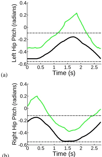
1) Similarity between Human Motion and Robot Motion The main indicator for accomplishing motion imitation is that the robot motion must bear a close resemblance to human motion. In this work, similarity between the two movements is enforced by the cost function of the proposed framework that maximizes similarity between human angle trajectories and robot trajectories as described in (3) and (4). Thus, the similarity between the angle trajectories of human and robot is examined in order to assess the similarity between the motions. As shown in Fig. 8(a) and Fig. 8(b), the Hip Pitch angles interpolated among optimized key frame angles have
the corresponding trend to human angles of the same joints. Despite the similarity observed through visual inspection,
Fig. 7. (a) Human walking gait acquired from the optical motion tracker and (b) the robot walking reproduced from the optical data.
quantification of the similarity between human and robot walking requires inspection of mean angle errors as listed in TABLE II. These values are the errors between human and optimized angles at the key frames. The errors of both Knee Pitch joints are, however, less than 14 due to the artificial constraint which maintains Knee Pitch angles at specific
values in order to avoid immediate change in the robot’s torso
height. The errors of both Hip Roll joints are relatively small as these errors are less than 4.5 . The errors of left and right Hip Pitch joints are lower than 8 which is acceptable. Although the differences in Knee Pitch joints are relatively large, Hip Pitch joints have a greater effect on foot positions than Knee Pitch joints because positions of the former joints are higher than those of the latter joints. Moreover, the mean error of all Hip Pitch, Hip Roll and Knee Pitch joints is 7.0296 . Therefore, the optimization framework is able to reproduce robot walking that is similar to human walking.
[image:7.612.46.297.71.235.2] [image:7.612.315.565.87.233.2]with the ground; therefore, during toe off, the robot’s foot is not tilted downwards and its ankle is not extended as much as that of human.
The main metric for motion similarity in this paper is mean joint angle error. The mean values of the hip pitch angle error can indicate similarity between the movements of a human subject and the robot because the knee pitch angles were constrained to be within a predefined range by one of the artificial constraints in (15). Therefore, without significant changes in the knee pitch angles, leg movements were mainly affected by the changes in the hip pitch angles. As shown in TABLE III, the mean values of the hip pitch joint angle errors were lower than 2 degrees. This demonstrated similar trends of hip pitch joint angles of both human and the robot and thus the similar movements.
The criteria used in motion imitation other than motion similarity in terms of joint angles [16] include minimum consumed energy (MCE) [41, 42, 43], minimum torque change (MTC) [44], maximum motion velocity (MMV) [45] and minimum joint velocities (MJV) [46]. The advantages of MCE criterion are that the generated motion was relatively similar to that of human; and battery life or operation time is long. The advantage of MTC criterion is that smooth variation in link acceleration and torque results in more stable generated motion [44]. MMV criterion was reported to produce gaits with increased speed but also required an additional constraint on foot impacts; and MJV criterion was reported to produce unnatural and non-smooth gaits with backward tilting of pelvis and fluctuation in pelvis height [46]. In the proposed method, motion similarity (MS) in terms of joint angles is used as the only criterion in the cost function because the implementation of the MS criterion is straightforward due to availability of joint angle trajectories; and it does not require derivation of forces acted on joints and joint torques as in MCE criterion. The proposed method considers only single motion criterion. However, human motion is resulted from a weighted combination of several motion criteria. The effect of using the combination as a cost function could be investigated, and the combinations that generate motion with desirable characteristics could be found in the future.
2) Feasibility of Motion
It is feasible for the robot to imitate human motion only if the joint angle is within the robot’s joint limits because motion can be produced through joint actuation. Therefore, in order to satisfy this requirement, the proposed approach includes the mechanical constraint defined in (14). To evaluate the feasibility of motion, optimized joint trajectories are tested whether they are within the mechanical limits. As shown in Fig. 8, the trajectories of left Hip Pitch and right Hip Pitch are
within the robot’s joint limits. Particularly during the period
from 1 to 1.5 seconds, angles of right Hip Pitch do not go beyond the lower limits of the joint due to the optimization framework and interpolation method which preserves the shape of the trajectory. Thereby, motion feasibility is achieved.
3) Robot Balance during Walking Imitation
The condition that determines the success of walking and other whole body movements is the robot balance. The static
(a)
[image:8.612.347.516.90.350.2](b)
Fig. 8. The joint angle trajectories of (a) left Hip Pitch joint and (b) right Hip Pitch joint during a walking cycle. The trajectories include the trajectories of human (green) and the trajectories of the robot (black). The robot trajectories were interpolated among the optimized angles at the key frames.
equilibrium can be maintained if actual CoM position is inside the support area. However, for dynamic stability, CoM position can be outside the support region for a short duration during walking. Since the robot’s torso position is used to approximate the CoM position, actual torso positions were computed by using angle trajectories and forward kinematics. Angle trajectories were derived by cubic polynomial interpolation among optimal angle configurations at the key
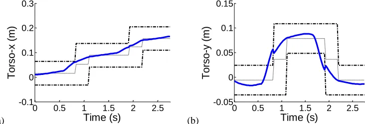
locomotion frames. The robot’s torso trajectories in x-axis and y-axis are shown in Fig. 9. The x-axis torso positions are within support region for the whole period of walking. The majority of y-axis torso positions are within support region. However, the parts of y-axis torso positions which account for approximately 9.8039% of a gait cycle time are outside of the support region. This occurred during transferring the projection of mass between two feet. This gait was considered dynamically balanced because, by definition, dynamically balanced gait occurs even if the floor projection of the CoM is outside the support region while the ZMP is within the support region [47]. Moreover, torso trajectories in both axes are in proximity to the middle positions of the support region because the reference torso positions are set to be the center of the foot during left foot support and right foot support. This trend of the trajectories indicates a relatively high degree of stability. If there is any error in controlling the torso position, actual torso position close to the middle position will still be within the support region compared to the position that is close to the boundary of the support region. Accordingly, the torso trajectories exhibit the effectiveness of the proposed
0 0.5 1 1.5 2 2.5
-0.6 -0.4 -0.2 0 0.2 0.4
Time (s)
Left Hip Pitch
(radians)
0 0.5 1 1.5 2 2.5
-0.6 -0.4 -0.2 0 0.2 0.4
Time (s)
Right Hip Pitch
scheme in maintaining torso position inside the support area and preserving the robot balance.
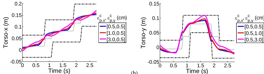
The threshold on stability criterion, as defined in (11), was selected for evaluation because the threshold controls the error or displacement between reference and actual CoM positions which relates to the stability of the robot. Since the reference positions are set to the center of support region, an increase in this error increases the chance of the actual position being outside the support region; and increases degree of instability. In order to investigate the effect of the threshold on stability
criterion on the robot’s stability, the threshold was set to
different values and the resulting torso positions during walking were inspected. Two groups of parameter settings as reported in Fig. 10 were used in this investigation. In Fig. 10(a), as the x-axis value of the threshold was increased, the torso positions in x-axis deviated from the reference positions by larger extent, particularly during the period between 0.5 and 1 second and the period between 1.5 and 2 seconds. In Fig. 10(b), as the y-axis value of the threshold was increased, the deviation of the torso positions in y-axis from the reference positions was larger, especially during the period from 1.5 to 2 seconds. Therefore, increasing the threshold on stability can introduce larger errors between torso positions and reference positions which may lead to higher degree of instability.
Generating dynamically stable gait is one of the contributions of this paper. Dynamically stable walk is defined as walking motion with the ZMP residing within the support region while the projection of the CoM on the floor being outside the support region [47]. The experimental results as illustrated in Fig. 9 demonstrated that the robot’s gait was dynamically stable and the robot does not experience a fall even though the projection of CoM was outside of the support region for approximate 9.8% of the entire walking period. This supports the contribution that the gait is dynamically stable.
4) Importance of Mechanical Constraints and Artificial Constraints
In order to investigate the importance of the mechanical constraints on the stability of robot motion, a detailed experiment was further conducted. The motion data captured with the Biomotion+ was processed twice by the proposed
framework: with and without mechanical constraints on Ankle Roll angles and Hip Roll angles. These constraints were those imposed within the optimization framework. Then, the Euler angles of torso orientation around x-axis and y-axis of the
global reference frame were computed by using the robot’s
kinematic model and shown in Fig. 11. In actual implementation, the specified minimal and maximal limits of Hip Roll joints are -12 and 8 , respectively. The specified minimal and maximal limits of Ankle Roll joints are -12 and 12 , respectively. The ranges of these limits are narrower than those of the real joints. Constraining Hip Roll and Ankle Roll joint angles directly affect the x-torso rotation, which represents rotation of the body towards the left or right direction. As shown in Fig. 11(b), the variation of x-torso rotation angles during a period from 0.75 to 1.25 seconds and a period from 1.75 to 2.25 seconds is greater than the variation of the angles in Fig. 11(a) during the same periods. The greater variation in x-rotation angles signifies more intense body sway, which can adversely affect the robot’s stability. Therefore, the mechanical constraints on Hip Roll and Ankle Roll angles can reduce variation in body sway around x-axis and thus improve stability.
Artificial constraints including the constraints on Knee Pitch angles, torso orientation and swing foot orientation were also required in our method. Constraining Knee Pitch angle of the robot, as described in (15), is needed because human walking requires considerable variation in knee angles in order to tilt a foot in a toe-off posture and detach the swing foot from the ground while the robot walking requires a foot to be flat, i.e. aligned with the ground, but does not require toe-off. Therefore, for the robot walking, the changes in Knee Pitch angle should be kept to be within a predefined range. Forcing the torso orientation to be within a predefined range, as described in (16), reduces the chance of falling because leaning the body too much in any direction would cause the CoM to be moved further from the centre of the support polygon. Constraining the orientation of swing foot to be aligned with the ground, as described in (18), is necessary since tilted swing foot would lead to undesirable contact between a swing foot and the ground, stumbling, and loss of balance.
(a) (b)
Fig. 9. Torso positions in (a) x-axis and (b) y-axis of robot walking. The lower and upper borders of the robot’s support region are represented by the two external dashed lines. Reference torso trajectories are represented by the middle dashed lines.
0 0.5 1 1.5 2 2.5 -0.1
0 0.1 0.2 0.3
Time (s)
T
o
rso
-x
(m
)
0 0.5 1 1.5 2 2.5 -0.05
0 0.05 0.1 0.15
Time (s)
T
o
rso
-y
(m
[image:9.612.118.484.538.663.2](a) (b)
Fig. 10. Torso positions of robot walking: (a) in x-axis when the x-axis value of the threshold in (11) is altered; and (b) in y-axis when the y-axis value of the threshold in (11) is altered. The values of the threshold on stability criterion in (11) are shown in the legends. The lower and upper borders of the robot’s support region are represented by the two external dashed lines. Reference torso trajectories are represented by the middle dashed lines.
[image:10.612.78.542.54.184.2](a) (b)
Fig. 11. Torso rotation angles (in degrees) during robot walking generated from optimization of the Biomotion+ data: (a) with mechanical constraints on Hip Roll and Ankle Roll angles and (b) without the mechanical constraints. Torso rotation angles around x-axis and y-axis are represented by normal lines and dashed lines, respectively.
TABLE III
MEAN OF ANGULAR ERRORS (IN DEGREES) OF HUMAN JOINT ANGLES AND OPTIMIZED ANGLES OF THE ROBOT’S JOINTS IN WALKING MOTION.THE ANGLES
WERE OBTAINED FROM CMUMOTION CAPTURE DATABASE.
Dataset
Joints 1 2 3 4 5 6 7 8 9 10 Mean
Left Hip Roll 4.1611 5.1575 4.5865 3.594 5.837 3.0465 6.2117 3.047 5.5377 4.3447 4.5524 Left Hip Pitch 1.5959 1.5872 1.7722 1.3432 1.7823 1.9397 1.6997 1.6819 1.6182 2.2668 1.7287 Left Knee Pitch 3.7369 3.9863 4.7411 3.4713 2.622 4.0583 2.6859 4.7924 4.4905 8.4944 4.3079 Left Ankle Pitch 9.9745 11.1923 9.9930 8.2771 13.2369 11.7410 13.5317 12.1934 7.3589 8.9315 10.6430 Right Hip Roll 6.3022 6.0538 8.6326 4.4643 6.0969 3.7428 5.9031 4.9911 8.0758 4.805 5.9068 Right Hip Pitch 1.5426 1.4943 1.6904 1.3282 1.7506 1.8633 1.6756 1.5786 1.5728 2.3458 1.6842 Right Knee Pitch 3.1551 2.7022 3.7172 3.2598 2.4389 3.7519 2.3983 2.7052 2.9958 6.6544 3.3779 Right Ankle Pitch 10.2651 9.7917 8.6809 6.2328 9.9994 9.6142 10.1827 9.2248 10.1855 11.5855 9.5763
IV. CONCLUSION AND FUTURE WORK
In this paper, we have presented a method for imitation of dynamic human gait by a humanoid robot. We modelled the task of dynamic motion imitation as an optimization process which minimizes differences between joint angle trajectories of human and robot. Constraints to the minimization were also considered to maintain the feasibility of the robot imitation. To maintain the robot balance, we presented a novel CoM trajectory strategy, which did not restrict the projection of the CoM within the foot support area, to make the robot imitation dynamically stable. Key motion frames in any gait cycle were also extracted. Only the angular data of key motion frames were optimized and continuous angle trajectories among these key frames were generated by interpolation. The method was verified by using both the wearable inertial sensor based
motion data and optical motion data. The experimental results have demonstrated the effectiveness of the proposed strategy for dynamic walking motion imitation.
The future work could involve extending the current method to deal with fast dynamic motions including running and full body movements with an intense angular momentum created by arm motion. This could be solved by considering ZMP as a stability criterion. The future work could also relate to improvement on the speed of walking and consideration of self-collision avoidance and higher derivatives of joint limits including angular velocity, acceleration and torque. Future work could involve considering energy minimization in the cost function of the optimization framework; and working on stabilization strategy without the artificial constraint on knee pitch angles in order to obtain more humanlike motion for a humanoid robot.
0 0.5 1 1.5 2 2.5 -0.05
0 0.05 0.1 0.15 0.2
Time (s)
T
o
rso
-x
(m
)
[0.5,0.5] [1.0,0.5] [3.0,0.5] c
p,x, c p,y (cm)
0 0.5 1 1.5 2 2.5 -0.05
0 0.05 0.1 0.15
Time (s)
T
o
rso
-y
(m
)
[0.5,0.5] [0.5,1.0] [0.5,3.0] c
p,x, c p,y (cm)
0 0.5 1 1.5 2 2.5
-15 -10 -5 0 5 10 15
Time (s)
0 0.5 1 1.5 2 2.5
-15 -10 -5 0 5 10 15
REFERENCES
[1] M. Fujita, Y. Kuroki, T. Ishida, and T. T. Doi, "Autonomous behavior control architecture of entertainment humanoid robot SDR-4X," in Proc. Proc. IEEE/RSJ Int. Conf. Intelligent Robots and Systems, 2003, pp. 960-967 vol.1.
[2] Y. Sakagami, "The intelligent ASIMO: system overview and integration," in Proc. IEEE/RSJ Int. Conf. Intelligent Robots and Systems, 2002, pp. 2478-2483.
[3] N. Yunjun, K. Bonkon, A. Cichocki, and C. Seungjin, "GOM-Face: GKP, EOG, and EMG-based multimodal interface with application to humanoid robot control," IEEE Trans. Biomed. Eng., vol. 61, pp. 453 - 462. 2014.
[4] J. Wainer, K. Dautenhahn, B. Robins, and F. Amirabdollahian, "Collaborating with Kaspar: using an autonomous humanoid robot to foster cooperative dyadic play among children with autism," in Proc. IEEE-RAS Int. Conf. Humanoid Robots, 2010, pp. 631-638.
[5] E. T. Bekele, U. Lahiri, A. R. Swanson, J. A. Crittendon, Z. E. Warren, and N. Sarkar, "A step towards developing adaptive robot-mediated intervention architecture (ARIA) for children with autism," IEEE Trans. Neural Syst. Rehabil. Eng., vol. 21, pp. 289-299. 2013.
[6] J. M. I. Zannatha, A. J. M. Tamayo, S. A.D., D. J.E., C. L.E., and A. W.A., "Development of a system based on 3D vision, interactive virtual environments, ergonometric signals and a humanoid for stroke rehabilitation," Comput. Methods Prog. Biomed., vol. 112, pp. 239-249. 2013.
[7] J. J. Diehl, L. M. Schmitt, M. Villano, and C. R. Crowell, "The clinical use of robots for individuals with Autism Spectrum Disorders: A critical review," Research in Autism Spectrum Disorders, vol. 6, pp. 249-262. 2012.
[8] A. Billard, B. Robins, J. Nadel, and K. Dautenhahn, "Building Robota, a mini-humanoid robot for the rehabilitation of children with autism," Assistive Technology, vol. 19, pp. 37-49, Mar. 2007.
[9] B. Robins, K. Dautenhahn, T. Boekhorst, and A. Billard, "Robotic assistants in therapy and education of children with autism: can a small humanoid robot help encourage social interaction skills?," Univers. Access Inf. Soc., vol. 4, pp. 105-120. 2005.
[10] P. Standen, D. Brown, J. Roscoe, J. Hedgecock, D. Stewart, M. Galvez Trigo, and E. Elgajiji, "Engaging students with profound and multiple disabilities using humanoid robots," in Universal Access in Human-Computer Interaction. Universal Access to Information and Knowledge, Lecture Notes in Computer Science, C. Stephanidis and M. Antona, Eds. Switzerland: Springer International Publishing, vol. 8514, 2014, pp. 419-430.
[11] K. Teachasrisaksakul, Z.-Q. Zhang, and G.-Z. Yang, "The use of BSN for whole body motion training for a humanoid robot," in Proc. Int. Conf. Body Sensor Networks, Zurich, Switzerland, 2014.
[12] D. Gouaillier, C. Collette, and C. Kilner, "Omni-directional closed-loop walk for NAO," in Proc. IEEE-RAS Int. Conf. Humanoid Robots, Nashville, TN, USA, 2010, pp. 448-454.
[13] A. Massah, A. Sharifi, Y. Salehinia, and F. Najafi, "An open loop walking on different slopes for NAO humanoid robot," in Proc. Int. Symp. Robotics and Intelligent Sensors, Kuching, Sarawak, Malaysia, 2012, pp. 296-304.
[14] S. Czarnetzki, S. Kerner, and O. Urbann, "Observer-based dynamic walking control for biped robots," Robotics and Autonomous Systems, vol. 57, pp. 839-845, Jul. 2009.
[15] Z. Li, N. Tsagarakis, and D. Caldwell, "Walking pattern generation for a humanoid robot with compliant joints," Autonomous Robots, vol. 35, pp. 1-14, 2013/07/01. 2013.
[16] S. Gaertner, M. Do, T. Asfour, R. Dillmann, C. Simonidis, and W. Seemann, "Generation of human-like motion for humanoid robots based on marker-based motion capture data," in Proc. Int. Symp. Robotics, Munich, Germany, 2010, pp. 1-8.
[17] N. S. Pollard, J. K. Hodgins, M. J. Riley, and C. G. Atkeson, "Adapting human motion for the control of a humanoid robot," in Proc. IEEE Int. Conf. Robotics and Automation, Washington, DC, USA, 2002, pp. 1390-1397.
[18] C. Ott, L. Dongheui, and Y. Nakamura, "Motion capture based human motion recognition and imitation by direct marker control," in Proc. IEEE-RAS Int. Conf. Humanoid Robots, 2008, pp. 399-405.
[19] B. Dariush, M. Gienger, J. Bing, C. Goerick, and K. Fujimura, "Whole body humanoid control from human motion descriptors," in Proc. Int. Conf. Robotics and Automation, 2008, pp. 2677-2684.
[20] W. Suleiman, E. Yoshida, F. Kanehiro, and J.-P. Laumond, "On human motion imitation by humanoid robot," in Proc. IEEE Int. Conf. Robotics and Automation, Pasadena, CA, USA, 2008, pp. 2697-2704.
[21] L. Jingru and K. Hauser, "Interactive generation of dynamically feasible robot trajectories from sketches using temporal mimicking," in Proc. IEEE Int. Conf. Robotics and Automation, St Paul, MN, USA, 2012, pp. 3665-3670.
[22] M. Vukobratovic, B. Bomvac, D. Surla, and D. Stokic, Biped Locomotion: Dynamics, Stability, Control and Application. USA: Springer, 1990, pp.
[23] S. Kim, C. H. Kim, B. You, and S. Oh, "Stable whole-body motion generation for humanoid robots to imitate human motions," in Proc. IEEE/RSJ Int. Conf. Intelligent Robots and Systems, St. Louis, USA, 2009, pp. 2518-2524.
[24] K. Hu and D. Lee, "Prediction-based synchronized human motion imitation by a humanoid robot," Automatisierungstechnik Methoden und Anwendungen der Steuerungs-, Regelungs- und Informationstechnik, vol. 60, pp. 651-720. 2012.
[25] J. Koenemann and M. Bennewitz, "Whole-Body Imitation of Human Motions with a Nao Humanoid," in Proc. ACM/IEEE International Conference on Human-Robot Interaction, 2012.
[26] L. Boutin, A. Eon, S. Zeghloul, and P. Lacouture, "From human motion capture to humanoid locomotion imitation: application to the robots HRP-2 and HOAP-3," Robotica, vol. 29, pp. 325-334, Mar. 2011. [27] BTS, "BTS Bioengineering," Website, available online at
http://www.btsbioengineering.com/, Oct 23, 2013.
[28] Vicon, "Vicon," Website, available online at http://www.vicon.com/, Oct 23, 2013.
[29] K. Yamane and J. Hodgins, "Simultaneous tracking and balancing of humanoid robots for imitating human motion capture data," in Proc. IEEE/RSJ Int. Conf. Intelligent Robots and Systems, St. Louis, MO, USA, 2009, pp. 2510-2517.
[30] C. D. Metcalf, R. Robinson, A. J. Malpass, T. P. Bogle, T. A. Dell, C. Harris, and S. H. Demain, "Markerless motion capture and measurement of hand kinematics: validation and application to home-based upper limb rehabilitation," IEEE Trans. Biomed. Eng., vol. 60, pp. 2184-2192. 2013. [31] Z.-Q. Zhang and G.-Z. Yang, "Calibration of miniature inertial and magnetic sensor units for robust attitude estimation," IEEE Trans. Instrum. Meas., vol. 63, pp. 711-718. 2014.
[32] Z.-Q. Zhang, X.-L. Meng, and J.-K. Wu, "Quaternion-based Kalman filter with vector selection for accurate orientation tracking," IEEE Trans. Instrum. Meas., vol. 61, pp. 2817-2824. 2012.
[33] Z. Zhang, A. Panousopoulou, and G.-Z. Yang, "Wearable sensor integration and bio-motion capture: a practical perspective," in Body Sensor Networks, 2nd ed. London: Springer London, 2014, pp. 495-526. [34] D. Gouaillier, V. Hugel, P. Blazevic, and C. Kilner, "Mechatronic design
of NAO humanoid," in Proc. IEEE Int. Conf. Robotics and Automation, Kobe, Japan, 2009, pp. 769-774.
[35] S. L. Altmann, Rotations, Quaternions, and Double Groups. Oxford, England: Clarendon Press, 1986, pp.
[36] A. Salarian, H. Russmann, F. J. Vingerhoets, C. Dehollain, Y. Blanc, P. R. Burkhard, and K. Aminian, "Gait assessment in Parkinson's disease: toward an ambulatory system for long-term monitoring," IEEE Trans. Biomed. Eng., vol. 51, pp. 1434-43, Aug. 2004.
[37] Aldebaran, "Locomotion control," Website, available online at http://doc.aldebaran.com/1-14/naoqi/motion/control-walk.html, Jan 12, 2015.
[38] M. J. D. Powell, "Variable metric methods for constrained optimization," in Mathematical Programming The State of the Art, A. Bachem, B. Korte, and M. Grötschel, Eds. New York: Springer-Verlag, 1983, pp. 288-311.
[39] R. Fletcher, Practical Methods of Optimization, 2nd ed. New York, USA: Wiley-Interscience, 1987, pp. 304-316.
[40] F. Fritsch and R. Carlson, "Monotone piecewise cubic interpolation," SIAM Journal on Numerical Analysis, vol. 17, pp. 238-246, Apr. 1980. [41] V.-H. Dau, C.-M. Chew, and A.-N. Poo, "Achieving energy-efficient
bipedal walking trajectory through ga-based optimization of key parameters," International Journal of Humanoid Robotics, vol. 06, pp. 609-629. 2009.
[43] C. A. Acosta Calderon, R. E. Mohan, L. Hu, C. Zhou, and H. Hu, "Generating human-like soccer primitives from human data," Robotics and Autonomous Systems, vol. 57, pp. 860-869. 2009.
[44] G. Capi, Y. Nasu, M. Yamano, and K. Mitobe, "Multicriteria optimal humanoid robot motion generation," in Humanoid Robots: New Developments, 2007, pp.
[45] C. Chevallereau and Y. Aoustin, "Optimal reference trajectories for walking and running of a biped robot," Robotica, vol. 19, pp. 557-569. 2001.
[46] K. Koch, K. Mombaur, and P. Souères, "Studying the Effect of Different Optimization Criteria on Humanoid Walking Motions," in Simulation, Modeling, and Programming for Autonomous Robots, Lecture Notes in Computer Science, I. Noda, N. Ando, D. Brugali, and J. Kuffner, Eds.: Springer Berlin Heidelberg, vol. 7628, 2012, pp. 221-236.