qubits by reduced fine-structure splitting
.
White Rose Research Online URL for this paper:
http://eprints.whiterose.ac.uk/91609/
Version: Accepted Version
Article:
Brash, A.J., Martins, L.M.P.P., Liu, F. et al. (4 more authors) (2015) High-fidelity
initialization of long-lived quantum dot hole spin qubits by reduced fine-structure splitting.
Physical Review B , 92 (12). 1301. ISSN 1098-0121
https://doi.org/10.1103/PhysRevB.92.121301
[email protected] https://eprints.whiterose.ac.uk/
Reuse
Unless indicated otherwise, fulltext items are protected by copyright with all rights reserved. The copyright exception in section 29 of the Copyright, Designs and Patents Act 1988 allows the making of a single copy solely for the purpose of non-commercial research or private study within the limits of fair dealing. The publisher or other rights-holder may allow further reproduction and re-use of this version - refer to the White Rose Research Online record for this item. Where records identify the publisher as the copyright holder, users can verify any specific terms of use on the publisher’s website.
Takedown
If you consider content in White Rose Research Online to be in breach of UK law, please notify us by
High-fidelity initialization of long-lived quantum dot hole spin qubits by reduced
fine-structure splitting
A. J. Brash,1L. M. P. P. Martins,1 F. Liu,1,∗ J. H. Quilter,1, 2 A. J. Ramsay,3 M. S. Skolnick,1and A. M. Fox1 1
Department of Physics and Astronomy, University of Sheffield, Sheffield, S3 7RH, United Kingdom
2
Department of Physics, Royal Holloway, University of London, Egham, TW20 0EX, United Kingdom
3
Hitachi Cambridge Laboratory, Hitachi Europe Ltd., Cambridge CB3 0HE, United Kingdom (Dated: September 25, 2015)
We demonstrate an on-demand hole spin qubit initialization scheme meeting four key requirements
of quantum information processing: fast initialization (1/e ~ 100 ps), high fidelity (F >99%), long
qubit lifetime (2Th> T2∗ ≃10 ns), and compatibility with optical coherent control schemes. This
is achieved by rapidly ionizing an exciton in an InGaAs quantum dot with very low fine-structure splitting at zero magnetic field. Furthermore, we show that the hole spin fidelity of an arbitrary quantum dot can be increased by optical Stark effect tuning of the fine-structure splitting close to zero.
PACS numbers: 78.67.Hc, 03.67.−a, 42.50.Ex, 85.35.Be
Single hole spins confined in semiconductor quantum dots (QDs) are an attractive stationary qubit candidate owing to their long coherence times1–3, ultrafast
opti-cal coherent control2–4and potential for integration with
circuit-style devices for quantum information processing (QIP)5–7. Initialization of a qubit to a well-defined state
is a critical part of any QIP protocol as it limits the fi-delity of the entire process. An ideal initialization scheme should be fast, operate on-demand and have high fideli-ties to permit error correction8,9, whilst long qubit
life-times are desirable to maximize the number of possible gate operations.
A range of single carrier spin initialization schemes have previously been demonstrated for both single QDs and quantum dot molecules. These include optical pumping10–12, coherent population trapping1,13 and the
ionization of an exciton14–18. Optical pumping methods
have reached fidelities as high as 99.8% in an out-of plane magnetic field10 with initialization times of the order of
µs. Faster (ns) initialization with slightly lower fideli-ties has been observed in an in-plane magnetic field11,13.
However, practical fault-tolerant QIP implementations8,9
require initialization that is very fast compared to deco-herence and hence it is desirable to further increase the initialization speed.
When driven by ultrafast pulsed lasers, exciton ion-ization schemes can offer both picosecond initialion-ization times and on-demand operation. Unfortunately, the anisotropic exchange interaction19,20 typically reduces
fidelity by causing spin precession during the exciton lifetime16,21,22 [see Fig. 1(b)]. Fast electron tunneling
minimizes this effect with fidelities ofF >96% obtained for ionization in QD molecules18 andF >97% for
prob-abilistic (continuous-wave (CW)) initialization of single QDs23. However, a negative consequence is the
reduc-tion of the hole qubit’s lifetime to 300 ps18 or 3 ns23
re-spectively. This is significantly less than the hole’s long extrinsic coherence time (T∗
2 ≃10 ns)1–4, reducing the
co-herence time (T2) and the number of possible gate
opera-tions. Application of a strong out-of-plane magnetic field
GaAs Substrate 25 nm GaAs InGaAs QDs
125 nm GaAs
75 nm AlGaAs 5 nm GaAs
12 nm Ti 100 nm Al
Laser
Electrical Contacts
Au Au
FS
(a) (b)
50 nm n+ doped GaAs
Figure 1. (a) Sample structure. A low density layer of InGaAs QDs is embedded in an n-i-Schottky diode. (b) Energy levels
in the circularly polarized basis at zero magnetic field where (↓
/↑) and (⇓/⇑) represent electron and hole spins respectively.
The neutral exciton (X0
) states are coupled by the FSS with
angular precession frequency δF S (green arrows) and decay
by electron tunneling at a rate Γe (blue dashed arrows) to
leave single holes (h). The hole spin state can be read out by
probing theh→X+ (positive trion) transitions usingσ+/−
polarized pulses.
inhibits spin precession resulting inF >99%21; however
out of plane fields are incompatible with present coherent control schemes1–3,24 which require in-plane spin
quanti-zation.
In this Rapid Communication we demonstrate F >
99% at zero magnetic field with on-demand, < 100 ps initialization and a hole lifetime that can be as high as 25.2 ns. This is achieved by exciton ionization in a QD with near-zero fine-structure splitting (FSS), rendering the precession due to the anisotropic exchange interac-tion negligible relative to the exciton lifetime. To demon-strate that such a scheme is also applicable to typical QDs with finite FSS, we use the optical Stark effect (OSE)25
to reduce the FSS26,27, resulting in increased fidelity.
[image:2.612.319.561.263.380.2]0 1 2 3 4 0 3 6 9 12 15 18
0 1 2 3 4
0 3 6 9 12 15 18
QD A X
+ P C , P C 2 p u ls e -P C s in g l e p u l s e ( p A )
Probe detuning, (meV)
CO CROSS X 0 QD E X + X 0
0 200 400 -8
-4 0 4
= 2.01 eV
(b)
Delay Time (ps)
P C X 0 C O -P C X 0 C R O S S ( p A )
= 31.2 eV
(a)
0 200 400 -8 -4 0 4 P C X 0 C O -P C X 0 C R O S S ( p A )
[image:3.612.54.295.53.182.2]Delay Time (ps)
Figure 2. Two-color pump-probe photocurrent spectra of
quantum dots exhibiting (a) negligible (2.01 µeV) and (b)
large (31.2 µeV) FSS. Spectra are measured at E = 72 kV
cm−1
and τ = 100 ps when only the hole is left in the QD.
Black (red) lines correspond to a co (cross)-polarized probe laser. Insets: The precession of the neutral exciton spin
mea-sured by time-resolved pump-probe spectroscopy31
. The ex-ponential damping of the fine-structure beats corresponds to
the exciton lifetime (1/ΓX).
2.01µeV (QD A) to 31.2µeV (QD E) were studied. The sample is held in a helium bath cryostat at 4.2 K and excited by transform-limited FWHM ≃0.2 meV pulses derived from a Ti:Sapphire laser with 76 MHz repetition rate. Photoexcited carriers in the QD are then detected by measuring the resulting photocurrent28.
Figure 1(b) illustrates the principle of the hole spin initialization scheme. A circularly-polarized laser pulse with π pulse area creates a neutral exciton (X0) in the
QD at time t = 0. Under a reverse bias DC elec-tric field (E) the exciton population decays at a rate ΓX = Γr+Γe+Γhwhere Γris the rate of radiative
recom-bination and Γeand Γhare the electron and hole
tunnel-ing rates respectively.Owtunnel-ing to the larger hole effective mass the electron tunneling rates exceed hole tunneling rates by around two orders of magnitude (Γe≫Γh).
Ra-diative recombination rates are slow compared to electron tunneling in our devices29,30 and hence Γ
X ≃ Γe. The
tunneling of the electron leaves behind a single hole with spin conserved from theX0; thus the initialization time
for the hole is equal to 1/Γe. The anisotropic exchange
in-teraction causes precession betweenX0
↑⇓andX↓⇑0 states
at angular frequency δF S, reducing the polarization of
the resultant hole spin.
To measure the initialized hole spin, a co (cross)-circularly polarized probe π pulse arrives after a delay (τ) with a detuning of ∆ relative to the first pulse. By scanning the probe detuning, two-pulse spectra like those shown in Fig. 2 are obtained where black (red) traces represent the co (cross)-polarized cases respectively . For presentation purposes, a single-pulse (probe only) spec-trum is subtracted from the two-pulse specspec-trum to re-move any weak spectral features not arising from the pumped QD; the dip at ∆ = 0 corresponds to subtrac-tion of the X0 peak. At ∆ equal to the positive trion
0 10 20 30 40
0.5 0.6 0.7 0.8 0.9 1.0 E D C B H o l e s p i n f i d e l i t y
Fine structure splitting ( eV) A
Figure 3. Fidelity vs. fine-structure splitting as measured
for QDs with different FSS. For all QDs,F was measured at
Γe= 0.021 ps−1. The red line is a calculation using Eq. 2.
(X+) binding energy theh→ X+ transitions shown in
Fig. 1(b) are probed. Peaks corresponding to these tran-sitions are observed in the spectra and the hole spin state may be extracted from their relative amplitudes.
Figure 2(a) shows the spectrum of QD A with a small FSS of 2.01µeV. The inset illustrates that exciton spin precession during electron tunneling is negligible; as a result, the hole spin preparation is almost ideal with no trion peak observed for a co-polarized probe. By con-trast, Fig. 2(b) shows the case of QD E with a large FSS of 31.2µeV. The exciton spin precession is seen clearly in the inset whilst prominent trion peaks in both spectra illustrate the reduced fidelity.
The fidelity32 of spin preparation is defined as F = h⇑ |ρ| ⇑i where ρ is the density matrix of the prepared spin state and⇑ (⇓) is the target spin state. Fidelity is evaluated using Eq. 1:
F = P C
X+
cross
P CX+
cross+P CX
+
co
, (1)
whereP CX+
cross andP CX +
co are the amplitudes of theX+
peaks in the co- and cross-polarized spectra.
To investigate the variation of F withδF S, the
fideli-ties of the five QDs with different FSS are measured at a constant electron tunneling rate (Γe) by varying
the DC electric field. The tunneling rates and FSS are measured by time-resolved pump-probe spectroscopy31,33
whilst the smallest FSS are measured with a narrow linewidth (FWHM < 10 neV) CW laser [see Ref. 34]. The data is shown in Fig. 3 where F falls as the fine-structure precession increases relative to electron tunnel-ing. AtB = 0 T, the hole spin fidelity is described by a model developed by Godden et al.21:
F = 1−12
"
δ2
F S
δ2
F S+ (ΓX−Γh)2
#
, (2)
where (ΓX−Γh) ≃ Γe due to slow radiative
[image:3.612.315.561.56.166.2]3
40 60 80 100 120 140
77.1 73.4 69.8 66.1 62.4 58.8
1 10 100
Electric field (kV cm
-1 ) t h H o l e l i f e t i m e ( n s )
Initialisation time (ps)
[image:4.612.55.299.54.197.2]0.90 0.92 0.94 0.96 0.98 1.00 Model Fidelity H o l e s p i n f i d e l i t y 2 2 T QD A
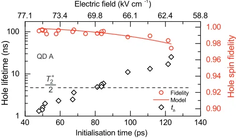
Figure 4. Hole lifetime (1/Γh) (diamonds) and fidelity lower
bound (red circles) plotted vs. initialization time (1/Γe) and
approximate DC electric field for QD A. Error bars are of the order of the data point size. The model (red line) represents a
fit of Eq. 2 with measured~δF S = 2.01±0.20µeV and fitting
parameter~χE=−0.0219±0.0007µeVV−1
cm corresponding to a small change in FSS with DC electric field [see Ref. 34].
good quantitative agreement with our results. For QD A (~δF S = 2.01±0.20µeV) a fidelity lower bound of F ≥0.993 is measured. This value is only limited by the noise present in the co-polarized spectrum and implies an initialization error rate below the 0.75% threshold re-quired for error correction43.
Owing to the negligible exciton spin precession of QD A, fast electron tunneling is no longer required to achieve high fidelities. This enables the reduction of the diode electric field to maximize the hole lifetime (Th = 1/Γh)
with a moderate increase in initialization time (1/Γe
which remains ≪ than the coherence time (T2)) and a
small change in FSS41. Previous studies on similar
sam-ples have shown that the coherence time of the hole spin is limited by the hole tunneling rate3(Γ
h) at typical
elec-tric fields. Beyond this, the next limit is the extrinsic pure dephasing time (T∗
2 ≃10 ns1–4) which most likely
originates from fluctuations in the electric field acting on the hole g-factor2,4,44. In the limit of negligible extrinsic
pure dephasing, or spin-flips, the coherence time is twice the hole lifetime. Thus, a good target is 2Th > T2∗, the
point at which pure dephasing rather than hole tunneling becomes the dominant limitation on the coherence time. To demonstrate this, Fig. 4 shows the results of mea-suring fidelity, initialization time and hole lifetime for a range of DC electric fields on the low FSS QD A. By treating the variation ofδF S with DC electric field as a
fitting parameter in Eq. 2 [see Ref. 34] we obtain ex-cellent agreement with the data [see red line]. At lower electric fields the maximum resolvable fidelity decreases due to reduced photocurrent, emphasizing that our mea-surements represent a lower-bound. For 2Th > T2∗ the
initialization time ranges from 83.5 ps to 123 ps with fi-delity lower bounds from≥0.974 to≥0.995, indicating that both high fidelity and long qubit lifetimes may be obtained for a QD with negligible FSS.
Due to the importance of low FSS QDs for polariza-tion entangled photon sources45,46, deterministic growth
of symmetric QDs is a topical area of research47–49 but
is yet to be demonstrated. As such, in-situ methods for tuning FSS are widely studied, using strain50,51,
magnetic52and laser26,27fields as well as both lateral53,54
and vertical55,56DC electric fields. In order to retain
con-trol over the qubit energy and lifetime it is desirable to tune the FSS using a field that is independent from the DC electric field. Thus we use a detuned CW laser to tuneδF S by the OSE25–27at a fixed DC electric field.
In our scheme the OSE is induced by a linearly po-larized CW laser which is positively detuned from the co-polarizedX →XX (biexciton) transition by ∆CW as
illustrated in Fig. 5(a). The neutral exciton eigenstates (XH/V) are linearly polarized along the in-plane crystal
axes and can be addressed individually by selecting the laser polarization. XH and XV are split by ~δF S; we
defineXV to be lower in energy. A positive-detunedV
-polarized laser addresses theXV state and acts to reduce δF S by Stark-shifting theXV state to higher energy. By
contrast, anH-polarized laser increases δF S by shifting
the XH state to higher energy. In the case of positive
detuning (∆CW >0), the change in FSS due to the OSE
(∆ω) is given by25:
∆ω= s
2
∆CW−
q ∆2
CW+|Ω|
2
(3)
where Ω is the Rabi splitting induced by the CW laser (proportional to the square-root of laser intensity √I) ands=±1 when the CW laser isH/V polarized. Sim-ilar to previous reports26,42, we observe a
polarization-independent blue-shift of the exciton energy withI. This arises due to charge screening from the large number of carriers generated in the surrounding material by the CW laser and results in a linear dependence of ∆CW onI.
In Fig. 5(b) the CW laser photon energy is fixed and the FSS of QD C is measured by time-resolved pump-probe spectroscopy [as in insets to Fig. 2] as a function of both laser intensity (I) and polarization. For a V -polarized CW laser (red circles), δF S reduces from its
initial value of~δF S = 13.2±0.1µeV to a minimum of ~δF S = 2.49±1.25µeV at I = 0.44 kW cm−2.
Con-versely, when the laser is H-polarized (blue diamonds)
δF Sincreases, proving that the change in FSS is induced
by the OSE. The solid lines show a fit of Eq. 3 to the data [see Ref. 34].
To demonstrate that reducing FSS leads to an increase in fidelity, hole spin fidelity was measured as a func-tion of CW laser intensity. The laser isV-polarized and
~△CW = 33.4µeV. The result of this measurement is
shown in Fig. 5(c); forI= 0.25kW cm−2(FSS≃8.7µeV)
0.0 0.1 0.2 0.3 0.4 0
4 8 12 16 20
Pump pulse
(b)
0
FS CW
V X
H X
QD C
H-polarized,
CW
= +76.6 eV
V-polarized,
CW
= +63.4 eV
F
S
S
(
e
V
)
XX
CW laser
0.0 0.1 0.2 0.3 0.70
0.75 0.80 0.85 0.90
CW laser intensity (kW cm
-2
)
(c)
H
o
l
e
s
p
i
n
f
i
d
e
l
i
t
y
CW laser intensity (kW cm
-2
) (a)
V-polarized
CW
= +33.4 eV
Figure 5. (a) QD energy levels in the linear basis where the neutral exciton eigenstates are split by δF S. The CW laser is
V-polarized and positively detuned from the XV →XX transition by△CW. The pump pulse addresses both exciton levels
owing to its circular polarization and FWHM≫δF S. (b) FSS vs. CW laser intensity for QD C with~δF S= 13.2µeV measured
atE= 60 kV cm−1
to resolve smallδF S. The blue diamonds (red circles) correspond to anH (V)-polarized CW laser which
addresses the high (low) energy exciton eigenstate. The solid lines are fits to Eq. 3. (c) Hole spin fidelity (measured as in Fig.
2) vs. CW laser intensity for aV-polarized CW laser atE= 72 kV cm−1 to maximize photocurrent detection efficiency. The
line is a fit of the model (Eq. 2) incorporating the variation ofδF S with CW laser intensity [see Ref. 34] .
maximumI is limited by photocurrent fluctuations due to laser power instability. This particularly limits the fi-delity measurement as atI >0.25 kW cm−2fluctuations
exceed the small (∼1 pA) co-polarized peak amplitude, limiting the maximum F that can be measured. How-ever, the agreement with the model and the large optical Stark shift observed in Fig. 5(b) indicate that fidelities as high as those measured for QD A could in principle be obtained with this method. We also note that the anti-crossing behavior seen with tuning methods such as strain57 does not occur for the OSE26.
In conclusion, we have demonstrated that a QD with very small FSS (2.01±0.20µeV) enables fast, on-demand initialization of a long-lived (2Th > T2∗ ∼ 10 ns) hole
spin qubit with fidelity ≥99.5% at B = 0 T, ex-ceeding the threshold required for a fault-tolerant QIP implementation43. Whilst the high fidelities here are
measured at zero magnetic field, we note that simulations with smallδF S show that F will remain very high even
under the presence of a modest in-plane magnetic field22.
As a result, this initialization scheme offers performance compatible with coherent control of hole spins1–3,24where
fast gate times (∼20 ps2,3), high gate fidelities (94.5%2)
and long coherence lifetimes have demonstrated an at-tractive qubit platform. We note that hole lifetimes could
be further extended by modulation of the electric field to a very low value between initialization and readout58.
Combining this with supression of extrinsic pure dephas-ing by optical spin echo59 could enable high fidelity
ini-tialization with coherence times in theµs regime. Furthermore, we have demonstrated that the initial-ization fidelity for arbitrary QDs with larger FSS can be increased by the OSE, providing additional motivation for FSS tuning studies26,27,50–56 that were typically
mo-tivated by the generation of entangled photon pairs45,46.
In our devices the DC electric field presents an extra tun-able parameter that may be used to optimize qubit life-times [see Fig. 4] or to tune two QDs into resonance. This presents a potential route towards fault-tolerant QIP schemes based on multiple long-lived hole spins on a single chip.
Note added in proof. Recently, we became aware of related results by another group60.
ACKNOWLEDGMENTS
This work was funded by the EPSRC (UK) programme grant EP/J007544/1. The authors thank H. Y. Liu and M. Hopkinson for sample growth and P. Kok for helpful discussions.
∗ To whom correspondence should be addressed:
FengLiu@sheffield.ac.uk
1
D. Brunner, B. D. Gerardot, P. A. Dalgarno, G. Wüst, K. Karrai, N. G. Stoltz, P. M. Petroff, and R. J.
Warbur-ton, Science325, 70 (2009).
2
K. De Greve, P. L. McMahon, D. Press, T. D. Ladd, D. Bisping, C. Schneider, M. Kamp, L. Worschech,
S. Hofling, A. Forchel, and Y. Yamamoto, Nat Phys 7,
872 (2011).
3
T. M. Godden, J. H. Quilter, A. J. Ramsay, Y. Wu, P. Br-ereton, S. J. Boyle, I. J. Luxmoore, J. Puebla-Nunez, A. M.
Fox, and M. S. Skolnick, Phys. Rev. Lett. 108, 017402
(2012).
4
A. Greilich, S. G. Carter, D. Kim, A. S. Bracker, and
D. Gammon, Nat Photon5, 702 (2011).
5
[image:5.612.63.551.53.188.2]5
A. Imamoglu, Nature491, 426 (2012).
6
K. De Greve, L. Yu, P. L. McMahon, J. S. Pelc, C. M. Natarajan, N. Y. Kim, E. Abe, S. Maier, C. Schneider, M. Kamp, S. Hofling, R. H. Hadfield, A. Forchel, M. M.
Fejer, and Y. Yamamoto, Nature491, 421 (2012).
7 N. Prtljaga, R. J. Coles, J. O’Hara, B. Royall, E. Clarke,
A. M. Fox, and M. S. Skolnick, Applied Physics Letters
104, 231107 (2014).
8 D. P. DiVincenzo, Fortschritte der Physik
48, 771 (2000).
9 J. Preskill, Proceedings of the Royal Society A:
Mathemat-ical, Physical and Engineering Sciences454, 385 (1998).
10
M. Atatüre, J. Dreiser, A. Badolato, A. Högele, K. Karrai,
and A. Imamoglu, Science312, 551 (2006).
11
X. Xu, Y. Wu, B. Sun, Q. Huang, J. Cheng, D. G. Steel, A. S. Bracker, D. Gammon, C. Emary, and L. J. Sham,
Phys. Rev. Lett.99, 097401 (2007).
12
D. Kim, S. E. Economou, S. C. Badescu, M. Scheib-ner, A. S. Bracker, M. Bashkansky, T. L. Reinecke, and
D. Gammon, Phys. Rev. Lett.101, 236804 (2008).
13
X. Xu, B. Sun, P. R. Berman, D. G. Steel, A. S. Bracker,
D. Gammon, and L. J. Sham, Nat Phys4, 692 (2008).
14 M. Kroutvar, Y. Ducommun, D. Heiss, M. Bichler,
D. Schuh, G. Abstreiter, and J. J. Finley, Nature 432,
81 (2004).
15
R. J. Young, S. J. Dewhurst, R. M. Stevenson, P. Atkinson, A. J. Bennett, M. B. Ward, K. Cooper, D. A. Ritchie, and
A. J. Shields, New Journal of Physics9, 365 (2007).
16
A. J. Ramsay, S. J. Boyle, R. S. Kolodka, J. B. B. Oliveira, J. Skiba-Szymanska, H. Y. Liu, M. Hopkinson, A. M. Fox,
and M. S. Skolnick, Phys. Rev. Lett.100, 197401 (2008).
17
D. Heiss, V. Jovanov, M. Bichler, G. Abstreiter, and J. J.
Finley, Phys. Rev. B77, 235442 (2008).
18
K. Müller, A. Bechtold, C. Ruppert, C. Hautmann, J. S. Wildmann, T. Kaldewey, M. Bichler, H. J. Krenner, G.
Ab-streiter, M. Betz, and J. J. Finley, Phys. Rev. B85, 241306
(2012).
19
D. Gammon, E. S. Snow, B. V. Shanabrook, D. S. Katzer,
and D. Park, Physical Review Letters76, 3005 (1996).
20 M. Bayer, G. Ortner, O. Stern, A. Kuther, A. Gorbunov,
A. Forchel, P. Hawrylak, S. Fafard, K. Hinzer, T. Reinecke, S. Walck, J. Reithmaier, F. Klopf, and F. Schäfer, Physical
Review B65, 195315 (2002).
21
T. M. Godden, S. J. Boyle, A. J. Ramsay, A. M. Fox, and
M. S. Skolnick, Applied Physics Letters97, 061113 (2010).
22 T. M. Godden, J. H. Quilter, A. J. Ramsay, Y. Wu, P.
Br-ereton, I. J. Luxmoore, J. Puebla, A. M. Fox, and M. S.
Skolnick, Phys. Rev. B85, 155310 (2012).
23 J. D. Mar, J. J. Baumberg, X. Xu, A. C. Irvine, and D. A.
Williams, Phys. Rev. B90, 241303 (2014).
24
J. Hansom, C. H. H. Schulte, C. Le Gall, C. Matthiesen, E. Clarke, M. Hugues, J. M. Taylor, and M. Atature, Nat
Phys10, 725 (2014).
25
T. Unold, K. Mueller, C. Lienau, T. Elsaesser, and A. D.
Wieck, Phys. Rev. Lett.92, 157401 (2004).
26 G. Jundt, L. Robledo, A. Högele, S. Fält, and
A. Imamoglu, Phys. Rev. Lett.100, 177401 (2008).
27
A. Muller, W. Fang, J. Lawall, and G. S. Solomon, Phys.
Rev. Lett.103, 217402 (2009).
28
A. Zrenner, E. Beham, S. Stufler, F. Findeis, M. Bichler,
and G. Abstreiter, Nature418, 612 (2002).
29 W. Langbein, P. Borri, U. Woggon, V. Stavarache,
D. Reuter, and A. D. Wieck, Phys. Rev. B70, 033301
(2004).
30
P. A. Dalgarno, J. M. Smith, J. McFarlane, B. D.
Ger-ardot, K. Karrai, A. Badolato, P. M. Petroff, and R. J.
Warburton, Phys. Rev. B77, 245311 (2008).
31 A. F. A. Khatab, A. J. Ramsay, S. J. Boyle, A. M. Fox,
and M. S. Skolnick, Journal of Physics: Conference Series
245, 012010 (2010).
32 R. Jozsa, Journal of Modern Optics
41, 2315 (1994).
33
R. S. Kolodka, A. J. Ramsay, J. Skiba-Szymanska, P. W. Fry, H. Y. Liu, A. M. Fox, and M. S. Skolnick, Phys. Rev.
B75, 193306 (2007).
34
See Supplemental Material (which follows the manuscript) for further details of the measurement techniques and the models used, which includes Refs. [21, 23, 24, 27, 29, 31-38].
35
T. M. Godden, Coherent optical control of the spin of a
single hole in a quantum dot, Ph.D. thesis, University of Sheffield (2012).
36
J. H. Quilter, Coherent spectroscopy of single quantum
dots, Ph.D. thesis, University of Sheffield (2014).
37 P. W. Fry, I. E. Itskevich, S. R. Parnell, J. J. Finley, L. R.
Wilson, K. L. Schumacher, D. J. Mowbray, M. S. Skolnick, M. Al-Khafaji, A. G. Cullis, M. Hopkinson, J. C. Clark,
and G. Hill, Physical Review B62, 16784 (2000).
38
S. Stufler, P. Ester, A. Zrenner, and M. Bichler, Applied
Physics Letters85, 4202 (2004).
39
P. Ester, S. Stufler, S. Michaelis de Vasconcellos, M.
Bich-ler, and A. Zrenner, Physica Status Solidi (c) 3, 3722
(2006).
40
J. Houel, A. V. Kuhlmann, L. Greuter, F. Xue, M. Poggio, B. D. Gerardot, P. A. Dalgarno, A. Badolato, P. M. Petroff, A. Ludwig, D. Reuter, A. D. Wieck, and R. J. Warburton,
Phys. Rev. Lett.108, 107401 (2012).
41 E. Kadantsev and P. Hawrylak, Phys. Rev. B
81, 045311
(2010).
42
X. Xu, B. Sun, P. R. Berman, D. G. Steel, A. S. Bracker,
D. Gammon, and L. J. Sham, Science317, 929 (2007).
43
R. Raussendorf and J. Harrington, Phys. Rev. Lett. 98,
190504 (2007).
44
A. V. Kuhlmann, J. Houel, A. Ludwig, L. Greuter, D. Reuter, A. D. Wieck, M. Poggio, and R. J. Warburton,
Nat Phys9, 570 (2013).
45
R. M. Stevenson, R. J. Young, P. Atkinson, K. Cooper,
D. a. Ritchie, and a. J. Shields, Nature439, 179 (2006).
46
N. Akopian, N. H. Lindner, E. Poem, Y. Berlatzky, J. Avron, D. Gershoni, B. D. Gerardot, and P. M. Petroff,
Physical Review Letters 96, 130501 (2006), 0512048v2
[arXiv:quant-ph].
47
J. Treu, C. Schneider, A. Huggenberger, T. Braun, S. Re-itzenstein, S. Höfling, and M. Kamp, Applied Physics
Let-ters101, 022102 (2012).
48
G. Juska, V. Dimastrodonato, L. O. Mereni, A.
Gocalin-ska, and E. Pelucchi, Nat Photon7, 527 (2013).
49 Y. H. Huo, A. Rastelli, and O. G. Schmidt, Applied
Physics Letters102, 152105 (2013).
50
S. Seidl, M. Kroner, A. Högele, K. Karrai, R. J. Warbur-ton, A. Badolato, and P. M. Petroff, Applied Physics
Let-ters88, 203113 (2006).
51
R. Trotta, E. Zallo, C. Ortix, P. Atkinson, J. D. Plumhof, J. van den Brink, A. Rastelli, and O. G. Schmidt, Phys.
Rev. Lett.109, 147401 (2012).
52
R. M. Stevenson, R. J. Young, P. See, D. G. Gevaux,
K. Cooper, P. Atkinson, I. Farrer, D. A. Ritchie, and
A. J. Shields, Phys. Rev. B73, 033306 (2006).
53
91, 183104 (2007).
54
B. D. Gerardot, S. Seidl, P. A. Dalgarno, R. J. Warburton, D. Granados, J. M. Garcia, K. Kowalik, O. Krebs, K. Kar-rai, A. Badolato, and P. M. Petroff, Applied Physics
Let-ters90, 041101 (2007).
55 A. J. Bennett, M. A. Pooley, R. M. Stevenson, M. B. Ward,
R. B. Patel, A. B. de la Giroday, N. Skold, I. Farrer, C. A.
Nicoll, D. A. Ritchie, and A. J. Shields, Nat Phys6, 947
(2010).
56 M. Ghali, K. Ohtani, Y. Ohno, and H. Ohno, Nat
Com-mun3, 661 (2012).
57
J. D. Plumhof, V. Křápek, F. Ding, K. D. Jöns, R. Hafen-brak, P. Klenovský, A. Herklotz, K. Dörr, P. Michler,
A. Rastelli, and O. G. Schmidt, Phys. Rev. B83, 121302
(2011).
58 J. H. Quilter, R. J. Coles, A. J. Ramsay, A. M. Fox,
and M. S. Skolnick, Applied Physics Letters102, 181108
(2013).
59 D. Press, K. De Greve, P. L. McMahon, T. D. Ladd,
B. Friess, C. Schneider, M. Kamp, S. Hofling, A. Forchel,
and Y. Yamamoto, Nat Photon4, 367 (2010).
60 P.-L. Ardelt, T. Simmet, K. Müller, C. Dory, K. A. Fischer,
A. Bechtold, A. Kleinkauf, H. Riedl, and J. J. Finley, Phys.
1
Supplemental Materials: High-fidelity initialization of long-lived quantum dot hole
spin qubits by reduced fine-structure splitting
1. Measurements of fidelity
Fidelity is measured according to Eq. 2 in the body of the paper. For very high fidelities, it is no longer reliable or meaningful to fit a Gaussian peak to the co-polarized spectrum. In this case we use the variance of the photocurrent noise to estimate the amplitude35 and report a lower bound. We sample the datapoints within the laser FWHM of
the trion energy and then calculate the amplitude estimate (ǫ) as in Eq. S1:
ǫ= √σ
N, (S1)
where N is the number of datapoints within the sample and σ is their standard deviation. The quantity ǫ then replacesP CX+
co in Eq. 2 to calculate the lower bound ofF.
2. Conversion of biased voltage to DC electric field
The application of a reversed biased voltage (V) generates a direct current (DC) electric field (E) inside the diode structure. The voltage can be converted to electric field accroding to36:
E= (V +Vbi)/Wi, (S2)
whereVbi(∼0.76 V) is the built-in voltage of the diode. Wi(230 nm) is the distance between the Ohmic and Schottky
contacts.
3. Measurement of small FSS
In order to measure small FSS we use a narrow linewidth CW laser (FWHM ∼ 1 MHz) operating at a fixed wavelength to perform high resolution photocurrent spectroscopy37–39. The 0→X transition is Stark-shifted through
1 .2
9 4
3 1
.2 9
4 4
1 .2
9 4
5 1
.2 9
4 6 5
10 15 20 25 30
0 90 180 270 360 0 4 8 12 0 90 180 270 360
0 4 8 12
E
n
e
r
g
y
s
h
i
f
t
(
e
V
)
P
h
o
t
o
c
u
r
r
e
n
t
(
p
A
)
Energy (eV) (a)
(c)
FS
= 2.01 eV (b)
FS
= 10.1 eV
plateangle (deg.)
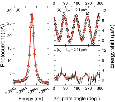
Figure S1. (a) Typical high-resolution photocurrent spectrum of a QD with Lorentzian fit (red line) of linewidth FWHM =
39.3±0.3µeV. Plot of the neutral exciton energy of QDs with (b) moderateδF S and (c) very smallδF S (QD A) as a function
of half-wave plate angle. Red lines: Fitting with sin2(θ) function. The amplitude of the fits yields a fine structure splitting of
~δF S = 10.1±0.1µeV and 2.01±0.2µeV respectively.
Rotating the linear polarization angle of the CW laser with a half-wave plate causes the exciton energy to oscillate with an amplitude of ~δF S as illustrated for a QD with moderateδF S (10.1±0.1µeV) and very smallδF S (2.01±
0.20µeV) (QD A) in Fig. S1(b) and (c).
4. Model of fidelity vs. applied DC electric field
The key modification to the model of Eq. 1 for experiments at non-constant DC electric field [see Fig. 4 in the main paper] is to consider the variation of FSS with DC electric field41. In this case the expression for FSS is defined
by Eq. S3:
δF S(E) =δF SE
0 +χE[E−E0], (S3)
whereδF SE
0 is the FSS evaluated atE0andχE is a linear gradient of FSS withE. The linear gradient represents a
good approximation of the form ofχE however full calculations require numerical methods41. For larger FSS we can
simply measure~χE [as shown in Fig. S2] using time-resolved pump-probe measurements [as shown in the insets to
Fig. 2 of the main paper] . The fittings give~χE= 0.25±0.04µeV V−1cm for QD E and−0.10±0.02µeV V−1cm
for QD C. These values are consistent with the literature value (0.285 µeV V−1 cm) reported by Bennett et al.34
and align with the theoretical prediction that smaller values ofδF S (i.e. initial QD anisotropy) give smaller values of
χE41.
As such, we expect a very small value of~χEfor QD A (~δF S= 2.01±0.20µeV). Since the FSS of QD A is already
more than an order of magnitude smaller than the QD linewidth [see Fig. S1], χE is used as a fitting parameter.
Inserting Eq. S3 into the model of Godden et al.21[Eq. 2 in the main text] and fittingχ
Eproduces the line shown in
Fig. 4 of the paper. The extracted value of~χE=−0.0219±0.0007µeV V−1cm is physically reasonable and again
agrees with the expected trend betweenδF S andχE.
5. Fine structure splitting vs. CW laser intensity
To demonstrate the tuning ofδF S using OSE, we measured the FSS of dot C by time-resolved pump-probe31with
[image:9.612.186.428.53.269.2]3
60 65 70 75
10 15 20 25 30 35 40
-0.10 eV V
-1
cm
h = 0.25 eV V
-1
cm QD C
QD E
F
i
n
e
s
t
r
u
c
t
u
r
e
s
p
l
i
t
t
i
n
g
,
|
|
(
e
V
)
DC electric field (kV cm
-1
[image:10.612.199.420.51.212.2])
Figure S2. Variation of FSS with DC electric field for QDs C and E with different values ofδF S. The labels show the values of
~χE extracted from the linear fits. The opposite signs result from the two QDs being elongated along orthogonal crystal axes
whilst the deviation of the red data points from the fit at high DC electric field corresponds to the onset of ΓX ≫δF S and
thus the resolution limit for a given QD and DC electric field. This figure is adapted from Ref.36.
0 200 400 600 800 0
5 10 15 20 25
0 200 400 600 800 0 5 10 15 20 25
P
h
o
t
o
c
u
r
r
e
n
t
(
a
r
b
.
u
n
i
t
s
)
P
h
o
t
o
c
u
r
r
e
n
t
(
a
r
b
.
u
n
i
t
s
)
Delay time (ps) (b) (a)
CW laser: H-polarized CW laser: V-polarized
I = 0.44 k W /cm
2
0.03 k W /cm
2
Delay time (ps)
Figure S3. Fine structure precession of the exciton spin vs. CW laser intensity I measured by time-resolved pump-probe
photocurrent technique. The CW laser is either (a)V- or (b)H-polarized and positively detuned from theX→XXtransition
(see Fig. 5(a) in the main paper). Detuning = 76.6 and 63.4µeV when the CW laser isH/V-polarized respectively. The CW
laser intensity ranges from 0.03 to 0.44 kW/cm2
. Red lines: Fitting with an exponentially damped sine function. Blue lines: guides for the eye.
shows the fine structure precession of the exciton spin vs. the CW laser intensityI. Since the smallest δF S that can
be resolved by this measurement is limited by the exciton decay time, a relatively low DC electric field (E = 60 kV cm−1) was used. When the CW laser is V-polarized [see Fig. S3(a)], the frequency of the fine structure precession
decreases with the CW laser intensity. AtI= 0.44 kW cm−2, no fine structure precession is observed, indicating that
a very small FSS close to the resolution limit of the time-resolved pump-probe measurement is achieved. By contrast, the frequency of the fine structure precession increases with CW laser intensity when the CW laser is H-polarized [see Fig. S3(b)], verifying that the change of the FSS is induced by OSE. δF S can be extracted by fitting the data
with an exponentionally damped sine function [see red lines]. The δF S vs. the CW laser intensity is shown in Fig.
[image:10.612.188.429.286.530.2]Polarization ~δF S|I=0(µeV) s a(meV2µm2 W−1
) ~△CW|I=0(µeV) k(eVµm2 W−1
)
H 13.2 +1 275 76.6 8.4
[image:11.612.124.494.52.94.2]V 13.2 −1 275 63.4 8.4
Table S1. Parameters used in the fits of FSS vs. CW laser power [see Fig. 5(b) in the main paper].
Polarization ~δF S|I=0(µeV) s a(meV2µm2 W−1) ~△CW|I=0(µeV)k (eVµm2 W−1) ΓX−Γh(ps−1)
V 13.2 −1 275 33.4 3.5 0.021
Table S2. Parameters used in the fit of hole spin fidelity vs. CW laser power [see Fig. 5(c) in the main paper].
6. Model of fidelity vs. OSE
The increase of the hole spin fidelity by reducing the FSS using OSE [see Fig. 5(c) in the main paper] can be well described by incorporting the OSE into the model of Godden et al.21 (see Eq. 2 in the main text). The FSS with the
presence of a CW laser postivltiy detuend from theX →XXtransition [see Fig. 5(a) in the main paper] is given by:
δF S(I) =δF S|
I=0+∆ω, (S4)
∆ω= s
2
∆CW−
q
∆2
CW+|Ω|
2
, (S5)
whereI is the CW laser intensity. ∆ω is the change of the FSS induced by OSE25. ∆
CW is the detuning of the CW
laser. s=±1 when the CW laser isH/V polarized. Ω =√aI/~is the Rabi splitting induced by the CW laser. ais
a fitting parameter proportional to the optical dipole momentum of theX →XX transition. In these experiments a linear blue-shift of the 0 →XH/V transitions with laser intensity is observed when the CW laser is applied26,42.
This effect is independent of laser polarization, we thus attribute the shift to charge screening from the large number of carriers generated in the surrounding material by the CW laser as in previous studies26,42. A similar blue shift is
expected for theX →XX transition; hence ∆CW is dependent on the incident CW laser intensity (I) according to:
∆CW(I) = ∆CW|
I=0−kI/~, (S6)
wherekis a fitting parameter. Fig. 5(b) in the main paper showsδF Svs. the CW laser intensity measured atE= 60
kV cm−1 and the fits according to Eq. S4. The parameters used in these fits are shown in Table S1.
Knowing how the FSS depends on the CW laser intensity, we now discuss the fidelity of the hole spin initialization vs. the CW laser intensity. To demonstrate the increase of the hole spin fidelity by reducing the FSS using OSE, the hole spin fidelity was measured as a function of the CW laser intensity [see Fig. 5(c) in the main paper]. This data can be well reproduced by including Eq. S4 in Eq. 2 in the main paper:
F = 1−12
"
(δF S|I=0+∆ω)2
(δF S|
I=0+∆ω)
2+ (Γ
X−Γh)2
#
, (S7)
where ΓX and Γh are the exciton and hole decay rate. Table S2 lists the parameters used in this fit. ais determined
from the fit of theδF Svs. CW laser intensity measured atE= 60 kV cm−1[see Fig. 5(b) in the main paper]. ΓX−Γh
[image:11.612.209.408.555.590.2]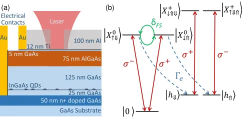


![Table S1. Parameters used in the fits of FSS vs. CW laser power [see Fig. 5(b) in the main paper].](https://thumb-us.123doks.com/thumbv2/123dok_us/7871340.182056/11.612.209.408.555.590/table-parameters-used-ts-fss-laser-power-paper.webp)
