Equivalent-Capacity-Based Design of Space-Time Block-Coded Sphere-Packing-Aided Multilevel
Coding
R. Y. S. Tee, O. Alamri, S. X. Ng and
1L. Hanzo
School of ECS, University of Southampton, SO17 1BJ, UK.
Email:
1[email protected], http://www-mobile.ecs.soton.ac.uk
Abstract–A multilevel coding (MLC) scheme invoking sphere packing (SP) modulation combined with space time block coding (STBC) is designed. The coding rates of each of the MLC com-ponent codes are determined using the so-called equivalent ca-pacity based constituent-code rate-calculation procedure invok-ing a 4-dimensional (4D) sphere packinvok-ing bit-to-symbol mappinvok-ing scheme. Four different-rate Low-Density Parity Check (LDPC) constituent-codes are used by the MLC scheme. The performance of the resultant equivalent capacity based design is characterized using simulation results. Our results demonstrate an approxi-mately 3.5dB gain over an identical scheme dispensing with SP modulation. Furthermore although a similar performance gain is attained by both the proposed MLC scheme and its benchmarker, which uses a single-class LDPC code, the MLC scheme is pre-ferred, since it benefits from the new classic philosophy of using low-memory, low-complexity component codes as well as provid-ing an unequal error protection capability.
1. INTRODUCTION
Coded modulation is based on jointly designed coding and modula-tion where the parity bits are accommodated by expanding the mod-ulated signal constellation, rather than by expanding the bandwidth required. An attractive example of coded modulation, namely multi-level coding (MLC) was proposed by Imai and Hirawaki [1], which protects each bit of a non-binary symbol with the aid of different-rate binary codes. An attractive iterative multistage decoding (MSD) scheme was also proposed in [1] for attaining a high decoding per-formance at a low decoding complexity. In this MSD structure, the
ith bit constituting a specific protection class associated with the con-stituent codeCiis decoded by theithdecoder, while simultaneously exploiting thea prioriinformation obtained from the demodulator, before passing the information to the (i+ 1)st protection level as-sociated with the constituent codeCi+1. This MSD process is acti-vated level by level at each different-rate component decoder, each of which constitutes a flexible component code that has numerous con-figurable parameters. The explicit advantage of having independently configurable parameters for the low-complexity component codes is that they may be appropriately adjusted for diverse applications.
In this paper, we employ a novel sphere packing (SP) modulation scheme combined with orthogonal transmit diversity design, which was introduced by Suet al.[2]. Various 2-dimensional (2D) bit-to-symbol mapping schemes have been investigated in [3] [4] and [5] with the motivation of improving the achievable bit error rate (BER) performance of MLC schemes with the aid of diverse bit-to-SP-symbol mapping strategies. In contrast to Alamouti’s inde-pendently modulated symbols transmitted within the two consecutive timeslots and two antennas [6], here we invoke a multidimensional SP strategy, where SP modulation is used for jointly designing the sym-bols transmitted within the consecutive time-slots of the Space Time Block Codes (STBC) invoked for transmission over Rayleigh fading
The financial support of the EPSRC, UK, Ministry of Higher Education of Saudi Arabia and that of the European Union under the auspices of the Phoenix and Newcom projects is gratefully acknowledged.
channels. Historically speaking, the STBC concept of Alamouti [6] was then further generalized by Tarokhet al.[7], but again, no at-tempt was made in [6] and [7] to jointly optimize the space-time signal design of the two consecutive time-slots and two antennas, although we will demonstrate that this results in substantial performance bene-fits. This is expected, because it is the joint space-time-symbol error probability that we would like to minimize for the sake of increasing the system’s integrity in fading channels.
The sphere packing aided concatenated design of STBCs [8] was further developed by Alamriet al.[9] by invoking an iterative turbo receiver. Motivated by the substantial performance improvements re-ported in [9], in this treatise we combine the SP concept with a MLC scheme for the sake of creating an improved orthogonal transmit di-versity design. The minimum Euclidean distance of symbols defined in an M-dimensional (MD) space may be maximized by finding the most meritorious mapping of the bits to the signalling constellation. It is worth noting, however that the choice of the best mapping typically depends on the channel conditions, as exemplified by the now classic Trellis Coded Modulation (TCM), arrangement designed for Gaus-sian channels [10], by Bit-Interleaved Coded Modulation (BICM) schemes proposed for Rayleigh channels [10] or by the design of [9]. The MD modulated symbols are then fed into the STBC encoder. We term this scheme as a Space-Time Sphere Packed Multilevel Coded Modulation (STBC-SP-MLC) arrangement.
A beneficial technique devised for determining each component code’s rate in MLC was detailed by Wachsmannet al.in [11], where the design concept exploited the so-called chain-rule of mutual infor-mation introduced in [12] as it will be detailed in Section 3. To elabo-rate a little further, the authors of [11] applied the equivalent capacity rules both to conventional one-dimensional and to two-dimensional modulated signal constellations. In this paper, we will further ex-tend the concepts proposed in [11] for improving the design of our STBC-SP-MLC scheme, invoking a 4-dimensional SP constellation. More explicitly, the equivalent capacity design [11] will be further developed for determining the optimum LDPC constituent code rates of the STBC-SP-MLC scheme in conjunction with various bit-to-SP-symbol mapping strategies in the 4D SP space. The BER performance of both the individual MLC protection classes as well as of the com-bined MLC scheme invoking the optimum LDPC coding rates will be evaluated by simulations.
The rest of this contribution is organized as follows. Section 2 provides an overview of our system, outlining our SP aided iterative MSD assisted MLC based decoder. The proposed equivalent capacity based design of the STBC-SP-MLC scheme is detailed in Section 3. Section 4 quantifies the achievable performance of this novel scheme, invoking the equivalent capacity based coding rates, while our con-clusions are presented in Section 5.
2. SYSTEM OVERVIEW
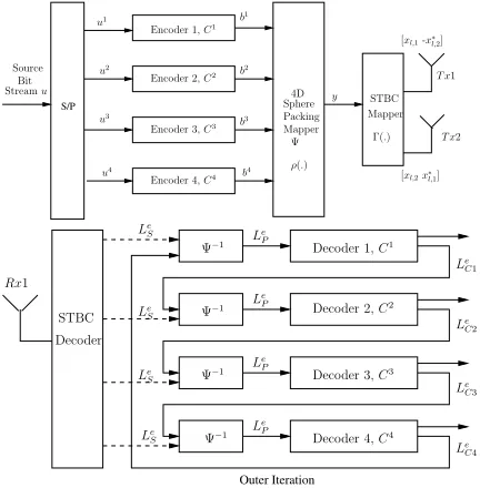
The schematic of the proposed STBC-SP-MLC arrangement is shown in Figure 1. The binary source bit streamuis serial-to-parallel (S/P) converted at the transmitter. The four individual source bits, namely
seen in Figure 1. The output bits of encoderCi,i= 1...4, having a total encoded frame length ofnbits are denoted asbi=bi1, bi2, ..., bin.
S/P StreamBit u
Source
u1
u2
u3
u4
b2
b1
b3
b4
y
Mapper
T x1
Mapper Packing Sphere
T x2
4D STBC
Encoder 3,C3
Encoder 4,C4
Ψ Encoder 2,C2
Encoder 1,C1
[xl,1-x∗
l,2]
[xl,2x∗l,1] Γ(.)
ρ(.)
Outer Iteration
Decoder STBC
Le P
Le S
Le S
Le S
Le S
Le P
Le P
Le P
Le C1
Le C2
Le C3
Le C4 Rx1
Ψ−1
Ψ−1
Ψ−1
Ψ−1
Decoder 2,C2 Decoder 1,C1
Decoder 3,C3
[image:2.595.49.265.91.311.2]Decoder 4,C4
Figure 1: The Space-Time Block-Coded Sphere Packing aided Multilevel coding (STBC-SP-MLC) scheme.
Again, we employ LDPC component codes owing to their pow-erful error correcting capability, low complexity and flexible coding rates. The random nature of the parity check matrix construction of LDPC codes allows us to dispense with the employment of additional channel interleavers. Each LDPC codeword is decoded using the be-lief propagation algorithm [13]. The MLC encoded bit stream is then forwarded to the sphere packing modulatorψof Figure 1. Our 4D SP modulator hasL=16 constellation points. Since there are 24 immedi-ately adjacent neighbours having different Euclidean distances in the 4D SP constellation [14], we use that specific set of 16 points out of the entire set of 24, which exhibits the maximum Euclidean distance. The 4D SP phasor points are denoted asS=(al,1, al,2, al,3, al,4), where we havel=0,1,2, ..., L−1. Here we would like to represent the four individual coordinates ofS in the 4D SP-space using real values, while satisfying the SP-constraint of(a1+a2+a3+a4)=k, wherekis an even integer constant [14]. The total energy of the signal points is represented byE=L−1
l=0(|al,1|2+|al,2|2+|al,3|2+|al,4|2)
[9].
After SP-modulation, the 4D SP symbol is mapped to two complex-valued 2-bit symbols, before being fed into a STBC scheme using two transmit antennas. The bit-to-symbol mapping function of the system is denoted as [9]
Γ(ρ(b1, b2, b3, b4)) = Γ(al,1, al,2, al,3, al,4), = {al,1+jaa,2, al,3+jal,4}, = {xl,1, xl,2}, (1)
whereρ(.)is the SP function used for mapping the original input bits to the SP symbols andΓ(.)represents the mapping of the 4D SP sym-bols to the complex-valued 2-bit symsym-bolsxl,1andxl,2after STBC encoding. The throughput of the overall system islog2L/2, since each SP symbol is transmitted over two antennas in two consecutive time slots. When taking into account the employment of rate-r chan-nel coding, the effective throughput becomes1/r.log2L/2.
Figure 1 also shows the receiver of the system, where a STBC de-coder equipped with a single receive antenna is employed. The STBC decoder forwards its complex-valued symbols to the SP-demodulator
ψ−1of Figure 1 and the resultant bits are then decoded at the different-protection LDPC decoders in an iterative MSD manner. At the initial
stage, the SP-demodulatorψ−1of Figure 1 only receives the chan-nel’s output information represented in terms of Log-Likelihood Ra-tios (LLR)LeS from the STBC decoder. TheextrinsicLLRsLeP of Figure 1 produced by the SP-demodulator are fed into the level-1 decoder ofC1, which then outputs a set of correspondingextrinsic
LLRsLe
C1to the demodulator. This LLR provides usefula priori
in-formation for the SP demodulator, where the LLRs gleaned from the previous protection level are updated. As the decoding process con-tinues, each MSD level receives usefula prioriLLRs from the pre-vious MSD level, which can be exploited in the LDPC decoder. The next outer iteration seen in Figure 1 commences, when the LLR infor-mation of the SP-demodulator has been updated with theextrinsic
information received from all MSD levels.
Alamriet al.[9] showed that the SP symbolrreceived by the STBC decoder can be written as
r=h·
2L E ·s
l+w
, (2)
where we haveh= (|h1|2+|h2|2)andh1as well ash2represent the channel impulse response (CIR) corresponding to the first and second transmit antennas. Furthermore, we havesl∈S,0≤l≤L−1, and wis a 4D real valued Gaussian random variable having a covariance matrix ofσw2 ·IND =h·σ2n·IND. The subscript ofND=4 indi-cates that the symbol constellationSis four-dimensional andINDis a (NDxND)-dimensional identity matrix.
The max-log approximation of theextrinsicLLR of a single bit
bkoutput by the demodulator can be expressed as
L(bk|r)−La(bk)
= maxsl∈Sk
1
− 1
2σ2
w
(r−α·sl)(r−α·sl)T+ B−1
j=0,j=k
bjLa(bj)
− maxsl∈Sk
0
−2σ12
w
(r−α·sl)(r−α·sl)T+ B−1
j=0,j=k
bjLa(bj)
,
(3)
where the SP symbols carryBnumber of MLC bits,b=b0,...,B−1∈
{0,1}. Let us assume furthermore thatSk1andSk0represent two
spe-cific 2D subsets of the 4D SP symbol constellationS, which obey
Sk
1 ={sl∈S:bk= 1}andS0k={sl∈S:bk= 0}, respectively. In general, for a MLC scheme havingq protection levels, the MLC-encoded bits are mapped to a total ofN=2qpossible SP sym-bols. The updateda prioriLLRs obtained from the preceding MLC protection-level at leveli= 1...4are given byLeCi{La(bk);k∈ {tq+ (i−1), t= 0,1, ..., N}}.
3. EQUIVALENT CAPACITY DESIGN
The calculation of channel capacity is based on the maximization of mutual information over all the relevant parameters, where the capac-ity of a particular channel can be formulated asC= maxp(Si)I(Y;S). We then apply the so-called chain-rule of mutual information [11] as follows
I(Y;S) = I(Y;b1, b2, ..., bl)
= I(Y;b1) +I(Y;b2|b1) +...
+I(Y;bl|b1, b2, ..., bl−1), (4)
whereY denotes the legitimate received signal set,Srepresents the legitimate transmitted symbol set andbi,i= 1...4, denotes the indi-vidual binary bits of the different protection levels.
[image:2.595.309.544.343.424.2]Figure 1. The resultant signal is then transmitted over a correlated Rayleigh fading channel. Therefore each of the STBC symbols be-comes two-dimensional and has an unequal probability for the resul-tant signal constellation points, as it will be shown in the context of Table 1, once our discourse has reached a sufficiently detailed stage. The partitioning of the 4D SP constellation is exemplified in Figure 2 for the conceptually simpler stylized 1D scenario of 16-level Ampli-tude Shift Keying (16-ASK). The partitioning of the signal setScan be further divided into two parts, resulting in the subsets ofS(b1= 0) andS(b1 = 1), each containing a total of eight out of theL= 16
symbols. In each subset, for example at theithlevel of the subset
S(b1) = 0, the 8-symbol constellation segment can be further
sub-divided into the two 4-symbol subsets ofS(b1 = 0, b2 = 0)and
S(b1 = 0, b2= 1)at level(i+ 1), etc. The partitioning tree of the
signal set is completed, when the partitioned SP-constellation con-tains only a single symbol at levell. Please note again that in Figure 2 we used a simplified 1D 16ASK constellation for the sake of con-ceptual simplicity, since the 4D SP space cannot be readily portrayed graphically.
For a 2D STBC scheme, havingNt= 2transmitter andNr= 1 receiver antennas, the signalY received at the single antenna, can be represented as [15]
Y =
Nt
j=1
|hj|2X+ Ω =χ22N tS+ Ω, (5)
whereXis the 2D complex-valued received signal,hjrepresents the complex-valued Rayleigh fading coefficient andχ22N t represents a chi-squared distributed random variable having2Ntdegrees of free-dom. Furthermore,Ωdenotes the resultant equivalent noise at the STBC receiver having zero mean and a variance ofχ22NtN0/2per dimension, whereN0/2is the original noise variance per dimension. For the STBC-SP-MLC system of Figure 1 characterized in Equa-tion 5, which receives two complex-valued STBC symbols of the sig-nalYand transmits theM-ary 2D STBC signalsXm,m∈ {1,2, ..., M}, over the two STBC antennas in two consecutive timeslots, the corre-sponding conditional probability is given by
p(Y|Xm) =
1 πN0χ22Nt
exp −|
Y −χ2NtXm|2
χ22NtN0
. (6)
We consider the occurrence of all legitimate transmitted M-ary signals
Xmhaving a probability ofp(Xm)form∈ {1,2, ..., M}, where the mutual information betweenYandXm[12] can be expressed as
I(Xm;Y) = M
m=1
Y
p(Xm, Y)log2
p(X m, Y)
p(Xm)p(Y)
dY
=
M
m=1
Y
p(Y|Xm)p(Xm).
log2
p(Y|Xm) M
n=1p(Y|Xn)p(Xn)
dY· (7)
Expressing the mutual information with the aid of the entropy as
I(X;Y) =H(X)−H(X|Y), we arrive at
I(X;Y) = −
M
m=1
p(Xm)log2(p(Xm))
− M
m=1 p(Xm)E
log2
M
n=1
exp(ψm,n)
|Xm
,
(8)
where we haveψm,n=
−|χ22Nt(Xm−Xn)+Ω|2+|Ω|2
χ22NtN0 , whileE[A|Xm]
is the expectation ofAconditioned onXm.
Since the STBC-SP-MLC scheme invokes a single receive and two transmit antennas, there are two modulated STBC symbols, each gleaning the amount of mutual information quantified by Equation 8. The total mutual information between a transmitted 4D SP symbol and the received 4D SP symbol is the average of that of the two 2D STBC symbols expressed as follows
I(S;Y) =I
1(X1;Y1) +I2(X2;Y2)
2 , (9)
whereIidenotes the mutual information between theithtransmitted STBC signalYiand theM-ary 2D received signalXi,i∈ {1,2}. The information gleaned at the MLC protection levelican be calcu-lated from the chain rule of Equation 4 according to [11]1
I(Y;bi|b1...bi−1) = I(Y;bi...bl−1|b1...bi−1)
− I(Y;bi+1...bl−1|b1...bi). (10)
4. SIMULATION RESULTS
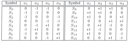
In this section we embark on quantifying the equivalent capacity for the sake of determining the corresponding coding rate of each of the four LDPC protection classes for our proposed STBC-SP-MLC scheme outlined in Figure 1, when communicating over a Rayleigh fading channel having a normalized Doppler frequency offD.T=0.1. We set the total effective throughput of the system after taking into account a code-rate of 0.5 to 1 bit/channel use, corresponding to 4 bit/SP-symbol for our twin-antenna design and construct benchmark-ers having the same effective throughput for comparison. The SP sig-nal constellation pointsD4having the maximum Euclidean distance between adjacent or nearest-neighbour points at a given energy are shown in Table 1.
Symbol a1 a2 a3 a4 Symbol a1 a2 a3 a4
S0 0 -1 -1 0 S8 0 +1 +1 0
S1 -1 -1 0 0 S9 +1 +1 0 0
S2 -1 0 0 -1 S10 +1 0 0 +1
S3 0 0 -1 -1 S11 0 0 +1 +1
S4 0 -1 +1 0 S12 0 +1 -1 0
S5 -1 +1 0 0 S13 +1 -1 0 0
S6 -1 0 0 +1 S14 +1 0 0 -1
[image:3.595.309.534.383.456.2]S7 0 0 -1 +1 S15 0 0 +1 -1
[image:3.595.66.289.513.598.2]Table 1: The bit-to-SP-symbol mapping scheme maximizing the Euclidean distance between points, while maintaining the lowest possible energy. The corresponding modulated constellation is seen in Figure 3.
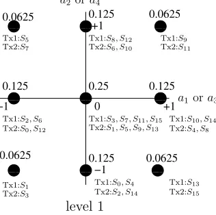
Figure 3 shows the resultant constellation point set of the STBC scheme’s 2D constellation mapper. The number seen above each constellation point indicates the probability of occurrence for each point, where the legitimate values ofa1...a4 in the signal space of Table 1 are constrainted to the various combinations of the values (±1,±1,0,0) according to our 4D SP spaceD4 [14]. For example, [a1a2a3a4]=[±1±1 0 0] or other alternative combinations as shown in Table 1. To elaborate a little further, when each SP symbol is mapped to two complex-valued 2D STBC symbols, they can be rep-resented as(a1+ja2, a3+ja4)according to Equation 1. Again, each of the variablesa1,a2,a3anda4may assume one of three possible values, namely±1,±1and 0, although recall that we selected the specific 16 combinations out of the 24 possible combinations, which maximize the Euclidean distance at a given average energy. Again, the SP symbols for allL= 16constellation points are specified in Table 1.
The STBC symbol (a1+ja2) of Equation 1 is mapped to the
1stSTBC transmitter of Figure 1, while (a3+ja4) is mapped to
2ndtransmitter. All the legitimate combinations of the(a1, a2)and
1The information provided by the bits of a non-binary symbol for each
0
10011 01
0 1 0 1 00 1101 0 1 00
11 0011 01 01001101000111
0 0 1 1
0 0 1 1 0
0 1 1 00 00 11 11 0 0 1 1 00 00 11 11
0 0 1 1
00 00 11 11
00 00 11 11
0 0 1 1
0 0 1 1
00 00 11 11
00 00 11 11
0 0 1 1
0 0 1 1
00 00 11 11
00
11 0011 01 01 01 01 0011 01
00 00 11 11
00
11 0011 00001111
0
1 0011
0000
0001 0010
0011 0100
0101 0111 1001 1010
1011 0110 1000 1100
1101 1111 1110
b1= 0 b1= 1
b1= 0, b2= 1
b1= 0, b2= 0
b1= 0, b2= 0, b3= 1
b1= 0, b2= 0, b3= 0
[image:4.595.57.539.64.290.2]b1= 0, b2= 0, b3= 0, b4= 0 b1= 0, b2= 0, b3= 0, b4= 1
Figure 2:16-ASK signal partitioning.
(a3, a4)values are plotted in Figure 3. We have a total of nine visi-bly different legitimate constellation points in Figure 3, because some of the points are identical as suggested by the associated doubled or quadrupled probability of occurence. For example, observe in Table 1 that the probability of the constellation point (-1,0), which is given byS2 and S6 of the first transmitter, is calculated as 2/16=0.125. Similarly, the probability of occurencefor all the specific constella-tion points is indicated by the number written above each point in Figure 3 and 4.
At the next MLC protection level, namely level 2, the signal rep-resenting the first STBC symbol of transmitter 1 is shown in Figure 4a and 4b. The resultant 5-point subsetsS(b1= 0)andS(b1 = 1) provide us with a partition tree ofS(0b2...bl)andS(1b2...bl). Given the knowledge of bitb1 at level 2, which identifies one of the two partitions seen in Figure 4, we obtain the partitioning ofS(b2...bl|b1)
at level 2 of the first transmitter. The two branches resulting from this partitioning yield the five unequal-probability constellation points shown in Figure 4.
The partitioning process continues from level 1 to levell. Since in the context of MSD we assume having virtually independent chan-nels for each protection level, the mutual information inferred at each protection levelican be calculated from Equations 8, 9 and 10.
00 00 00 11 11 11
00 00 11 11 00
00 11 11
0 0 1 1 00
00 00 11 11 11
00 00 00 11 11 11 00
00 11 11
00 00 11 11
00 00 11 11
0.25
0
−1
0.0625 0.0625
0.125
+1 0.125 0.0625
+1
0.0625
−1
0.125 0.125
Tx1:S5
Tx2:S7 Tx2:S6, S10 Tx1:Tx2:SS911
Tx1:S2, S6 Tx2:S0, S12
Tx1:S10, S14 Tx2:S4, S8
Tx1:S0, S4 Tx2:S2, S14
Tx1:S13 Tx2:S15 Tx1:S1
Tx2:S3
a1ora3
a2ora4
Tx1:S8, S12
level 1
Tx1:S3, S7, S11, S15 Tx2:S1, S5, S9, S13
Figure 3: The STBC constellation points at level 1. The number above the dots indicate the probability of occurrence for the symbols, while the sym-bol indices at the bottom indicate the specific symsym-bol. The first and second transmitter are represented by Tx1 and Tx2, respectively.
The overall effective system throughput of our proposed
STBC-SP-MLC scheme is given by
Rsys=
i=q i=1ki
i=q i=1ni
.Nsym.bpssp
Tr ,
(11)
wherekiandnidenote the number of source bits and encoded bits of the individual MLC component codes,Tris the total number of STBC timeslots used for transmitting the associated pairs of symbols, while
Nsymis the number of SP symbols at the input of the STBC encoder in a particular time slot. Finally,bpssp is defined as the number of bits per SP symbol.
Each LDPC component code has an output block length of 640 bits and their resultant combined MLC coding rate is 0.49609(≈1/2). We fix our overall effective system throughput after 1/2-rate coding to 1 bit/channel use. Observe in Equation 11 that the throughput of the SP-STBC scheme using no channel coding would be 2 bit/symbol.
Figure 5 shows the equivalent capacity curves detailed in Sec-tion 3. The vertical dashed line recorded for the throughput of 2 bit/symbol is used for determining the equivalent capacity for each protection level of the MLC scheme. Since the total throughput of the SP-STBC arrangement is 2 bit/symbol, the throughput of the in-dividual different-protection subchannels will sum up to be the same as the overall SP-STBC scheme’s throughput. According to [11], the vertical dashed line that cuts through all the equivalent subchannel ca-pacity curves determines the equivalent-caca-pacity-based coding rate of each component LDPC code. The coding rates determined from the equivalent capacity rules outlined at the end of Section 3 are (0.3478, 0.3043, 0.7174, 0.6413) and the actual LDPC code rates used are shown in Table 2.
[image:4.595.81.239.517.674.2]A total of 5000 frames containing 2560 MLC-encoded bits were transmitted for the sake of our BER evaluation. Our benchmarker is based on a STBC-MLC structure, which is constituted by the direct serial concatenation of STBC and MLC with conventional 16QAM modulation. The STBC employs two transmit antennas, a single re-ceive antenna and the MLC maps the output symbols into a 2D 16QAM Ungerb¨ock Partitioning (UP) based modulator. The LDPC coding rates for this STBC-MLC UP 16QAM benchmarker are also shown in Table 2, which were obtained by applying the capacity rules derived for UP-aided 16QAM at a code rate of 1/4 in [4].
signifi-0 0 0 1 1 1
0 0 0 1 1 1 0
0 1 1
0 0 0 1 1 1 0
0 0 1 1 1
0 0 0 1 1 1 0 0 1 1
0 0 1 1
0 0 0 1 1 1
0 0 0 1 1 1
0 −1
0.25 +1
+1 0.125
0.25
0.125 0.25
−1
0.25 0.125
0.25 0.25
0.125
0 +1
−1
+1
−1
(b) level 2,
b
1=1
(a) level 2 ,
b
1=0
S5
S2, S6 S3, S7
S0, S4
S1
S8, S12
S11, S15 S10, S14
S13
S9
a
2a
4a
3 [image:5.595.125.447.66.231.2]a
1Figure 4:The constellation points of the first STBC transmitter Tx1 at MLC level 2. The number above the dots indicate the probability of occurrence for the symbols, while the symbol indices at the bottom indicate the specific symbol.
awgn-capacity-mlc-3-8psk.gle
-5 0 5 10 15 20
Eb/N0(dB) 0.0
0.5 1.0 1.5 2.0 2.5 3.0
C
(bit/symbol)
. . . .
. . .
. .
. .
. .
. . .
. . . .
.
overall Level 3
[image:5.595.50.278.265.427.2].
Level 2 Level 1 Level 0Figure 5:The equivalent capacity curves of the proposed SP-STBC scheme communicating over correlated Rayleigh fading channels where a STBC scheme havingNt=2 andNr= 1antennas was used.
Coding rate R1 R2 R3 R4
[image:5.595.295.529.273.435.2]STBC-SP-MLC 221/640 193/640 458/640 408/640 STBC-MLC 48/640 228/640 84/640 280/640
Table 2:Coding rates of STBC-SP-MLC and STBC-MLC schemes.
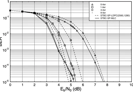
cantly enhanced with the aid of the proposed system employing the SP demapper. The BER curve dips below10−5using a single itera-tion atEb/N0=5.4dB. Upon employingI=4 iterations, the additional iteration-induced coding gain of the STBC-SP-MLC scheme becomes about 3.5dB at BER=10−5.
Observe in Figure 7 that a single-class 1/2-rate STBC-SP-LDPC scheme having an effective throughput of 1 bit/channel use was also used for comparison with our MLC structure, where the MLC codes of Table 2 were replaced by the single-class LDPC(2560, 1280) scheme having a coding rate of 1/2. All LDPC component codes employed in our simulations used a total of five iterations for generating suffi-ciently reliableextrinsicLLRs. The complexity of a single 2560-coded-bit LDPC code and that of the four 640-2560-coded-bit MLC-LDPC component codes of Table 2 was deemed similar in these systems. More explicitely, the LDPC decoding complexity of each iteration associated with a parity check matrix having a column weight ofj
and row weight ofkmay be approximated in terms of the number of additions and subtractions in the logarithmic domain [16]. The corre-sponding BER results are shown in Figure 7.
0 1 2 3 4 5 6 7 8 9
Eb/N0(dB)
10-5 10-4 10-3 10-2 10-1 1
BER
0 1 2 3 4 5 6 7 8 9
Eb/N0(dB) 10-5
10-4 10-3 10-2 10-1 1
BER
0-iter 1-iter 4-iter 9-iter STBC-SP-MLC STBC-MLC with UP 16QAM
Figure 6: BER versusEb/No performance of the STBC-MLC 16QAM
scheme at an effective throughput of 1 bit/symbol using Ungerb¨ock Parti-tioning (UP) based bit-to-symbol mapping and our proposed STBC-SP-MLC scheme, when communicating over a correlated Rayleigh channel having a Doppler frequency of 0.1. All other parameters are summarized in Table 2 and 3.
0 1 2 3 4 5 6 7 8 9 10
Eb/N0(dB)
10-5 10-4 10-3 10-2 10-1 1
BER
0 1 2 3 4 5 6 7 8 9 10
Eb/N0(dB) 10-5
10-4 10-3 10-2 10-1 1
BER
0-iter 1-iter 4-iter 9-iter
STBC-SP-LDPC(2560,1280) STBC-SP-MLC
Figure 7:BER versusEb/Noperformance of the proposed STBC-SP-LDPC
[image:5.595.299.529.509.671.2]Sphere packing modulation Largest Min. Euclidean Conventional modulation 16QAM, Ungerb¨ock P. MLC component output block length 640 bits STBC-SP-LDPC output block length 2560 bits
No. of LDPC iterations 5
LDPC column weight 3
Total number of frame 5000 Overall system throughput 1 bit/channel use
[image:6.595.67.275.64.148.2]Doppler frequency 0.1
Table 3:System parameters.
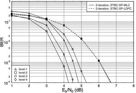
Our proposed STBC-SP-MLC system exhibits a similar BER per-formance to that of the single-class STBC-SP-LDPC structure charac-terized in Figure 7, although the proposed scheme has a slightly better performance at a low number of iterations. By contrast, the single-class scheme of Figure 7 performs approximately 0.45 dB better at a higher number of iterations at BER10−5. This is a consequence of the fact that each MLC component code has a four times lower codeword length compared to the single-class LDPC(2560, 1280) code. How-ever, the advantage of using MLC is the employment of shorter indi-vidual LDPC component codes, hence potentially requiring a lower memory and having the flexibility of freely adjusting the coding rates compared to other coded modulation schemes, which is beneficial for example according to the typical requirements of high-quality, error-resiliant audio or video transmissions. Figure 8 shows the individual BER performance curves of the proposed STBC-SP-MLC scheme in comparison to the single-class STBC-SP-LDPC scheme. AtI=2 iter-ation, all the bits in the single-class STBC-SP-LDPC scheme shows a similar BER performance. By contrast, the BER performance as-sociated with each protection level of the proposed STBC-SP-MLC scheme becomes different.
1 2 3 4 5 6 7 8
Eb/N0(dB)
10-4 2 5 10-3 2 5 10-2 2 5 10-1 2 5 1
BER
1 2 3 4 5 6 7 8
Eb/N0(dB) 10-4
2 5
10-3
2 5
10-2
2 5
10-1
2 5
1
BER
level-1 level-2 level-3 level-4
[image:6.595.53.287.388.548.2]2-iteration, STBC-SP-MLC 2-iteration, STBC-SP-LDPC
Figure 8:BER versusEb/Noperformance of the STBC-SP-LDPC scheme
using a single 1/2-rate component code LDPC(2560,1280) and having an ef-fective throughput of 1 bit/channel use in comparison to the proposed STBC-SP-MLC scheme, when communicating over a correlated Rayleigh fading channel. Each bit protection level is shown as an individual BER curve.
5. CONCLUSIONS
In conclusion, a novel STBC-SP-MLC scheme was proposed. The scheme invokes a serially concatenated LDPC-based MLC arrange-ment combined with STBC using SP modulation. The MLC scheme was decoded in a multistage manner [1]. A useful equivalent capacity based design was proposed for determining the coding rates of each of the component codes in this scheme. This proves to be crucial for the sake of achieving the best attainable BER performance in conjunction with different SP mapping schemes designed for the 4D
constella-tion space. Our simulaconstella-tion results outlined in Figures 5-8 character-ize the achievable performance. We can observe from Figure 6 that at an effective throughput of 1 bit/channel use, the proposed STBC-SP-MLC scheme is capable of achieving anEb/N0gain of about 3.5dB compared to the STBC-MLC benchmarker invoking classic 16QAM. Even though the proposed MLC-aided and the single-class STBC-SP-LDPC exhibit a similar performance, the multiclass scheme exhibits a higher flexibility and has the ability of providing an unequal error protection capability. Our future research will consider the design of different bit-to-SP-symbol mapping schemes for achieving unequal error protection with the aid the proposed equivalent capacity based design for determining individual component rates.
6. REFERENCES
[1] H. Imai and S. Hirawaki, “A New Multilevel Coding Method Using Error Correcting Codes,”IEEE Transactions on Information Theory, pp. 371– 377, May 1977.
[2] W. Su, Z. Safar, and K. J. R. Liu, “Space-Time Signal Design for Time-correlated Rayleigh Fading Channels,” inIEEE International Confer-ence on Communications, (Anchorage, Alaska), pp. 3175–3179, May 2003.
[3] M. Isaka, R. H. M-Zaragoza, M. P. C. Fossorier, S. Lin and H. Imai, “Multilevel Coded 16-QAM Modulation with Multistage Decoding and Unequal Error Protection,” inGlobal Communication Conference, vol. 6, (Sydney, Austrialia), pp. 3548–3553, November 1998.
[4] L. H-J. Lampe, R. Schober and R. F. H. Fischer, “Multilevel Coding for Multiple-Antenna Transmission,”IEEE Transactions on Wireless Com-munications, vol. 3, pp. 203–208, January 2004.
[5] D-F. Yuan, F. Zhang, A-F. So, Z-W. Li, “Concatenation of Space-Time Block Codes and Multilevel Coding over Rayleigh Fading Channels,” in
IEEE Vehicular Technology Conference, (Atlantic City, USA), pp. 192– 196, October Fall 2001.
[6] S. M. Alamouti, “A Simple Transmitter Diversity Scheme for Wireless Communications,”IEEE Journal on Selected Areas in Communications, vol. 16, pp. 1451–1458, October 1998.
[7] V. Tarokh, H. Jafarkhani and A.R. Calderbank, “Space-Time Block Codes from Orthogonal Designs,”IEEE Transactions on Information Theory, vol. 45, pp. 1456–1467, July 1999.
[8] W. Su, Z. Safar, and K. J. R. Liu, “Space-Time Signal Design for Time-correlated Rayleigh Fading Channels,”IEEE International Conference on Communications, pp. 3175–3179, May 2003.
[9] O. Alamri, B. L. Yeap, L. Hanzo, “Turbo Detection of Channel-Coded Space-Time Signals Using Sphere Packing Modulation,” inIEEE Ve-hicular Technology Conference, (Los Angeles, USA), pp. 2498–2502, September Fall 2004.
[10] L. Hanzo, T. H. Liew and B. L. Yeap,Turbo Coding, Turbo Equalisation and Space Time Coding for Transmission over Wireless channels. New York, USA: John Wiley IEEE Press, 2002.
[11] U. Wachsmann, R. F. H. Fischer and J. B. Huber, “Multilevel Codes: Theoretical Concepts and Practical Design Rules,”IEEE Transaction on Information Theory, vol. 45, pp. 1361–1391, July 1999.
[12] R. Gallager,Information Theory and Reliable Communication. New York: Willey, 1968.
[13] R. Gallager,Low Density Parity Check Codes. USA: MIT Press, 1963. [14] J. H. Conway and N. J. Sloane, “Sphere Packings, Lattices and Groups,”
Spinger-Verlag, 1999.
[15] S. X. Ng and L. Hanzo, “On the MIMO Channel Capacity of Multi-Dimensional Signal Sets,”IEEE Transactions on Vehicular Technology, vol. 55, pp. 528–536, March 2006.