City, University of London Institutional Repository
Citation
:
Li, Q., Yan, S. ORCID: 0000-0001-8968-6616, Wang, J. ORCID:
0000-0003-1821-2362, Ma, Q. ORCID: 0000-0001-5579-6454, Xie, Z. and Sriram, V. (2018). Numerical
simulation of focusing wave interaction with FPSO-like structure using FNPT-NS Solver. In:
Proceedings of the International Offshore and Polar Engineering Conference. (pp.
1458-1464). International Society of Offshore and Polar Engineers (ISOPE). ISBN
9781880653876
This is the accepted version of the paper.
This version of the publication may differ from the final published
version.
Permanent repository link:
http://openaccess.city.ac.uk/22494/
Link to published version
:
Copyright and reuse:
City Research Online aims to make research
outputs of City, University of London available to a wider audience.
Copyright and Moral Rights remain with the author(s) and/or copyright
holders. URLs from City Research Online may be freely distributed and
linked to.
City Research Online: http://openaccess.city.ac.uk/ [email protected]
Numerical simulation of focusing wave interaction with FPSO-like structure using FNPT-NS Solver
Qian Li1, S.Yan1, Jinghua Wang1, Q.W. Ma1, Zhihua Xie2, V Sriram3
1: School of mathematics, Computer science and engineering, City, University of London 2: School of Engineering, Cardiff University, Cardiff, UK
3: Department of Ocean Engineering, IIT Madras, Chennai, India
ABSTRACT
The paper presents the numerical results for the focusing wave interacting with a FPSO-like structure using the FNPT-NS solver. The case configuration is defined by CCP-WSI blind test in ISOPE 2018. The incident waves are uni-directional focusing waves with different spectrum bandwidths and wave heights. The structure is fixed and subjected to different heading. The numerical model used in present work is a hybrid model combining a fully nonlinear potential theory (FNPT) and a Navier-Stokes (NS )theory using a domain-decomposition approach. The Quasi Arbitrary Lagrangian Eulerian method is used to solve the FNPT in a large domain covering the entire wave basin with the same size as the experiments. For the later, the OpenFOAM (interDyMFoam) is utilized to achieve the solution near the structures, where the viscous effect may be important. In addition, the wave generation and the convergence of the hybrid model are discussed in detail.
KEY WORDS: FNPT-NS solver, hybrid method, focusing wave,
FPSO.
INTRODUCTION
It is nowadays increasingly recognized that accurate and efficient predictions of the wave load on offshore structures are very important for accessing their survivability in extreme weather conditions. Such assessments can always be performed in laboratory environment or in the numerical wave tanks, where the extreme waves are often modeled by using, e.g., the NewWave theory (Tromans, et al., 1991). In order to perform reliable predictions of the wave loads, classical approaches in frequency domain are employed, such as linear and second order theories, which however are shown to be insufficient when higher-order nonlinear effects are pronounced. Such higher-order nonlinearities are pointed out to play important roles in the interactions between extreme waves and structure (Zang, et al., 2010). To overcome this drawback, approaches in time domain while considering sufficient nonlinearities are developed, e.g., models based on the fully nonlinear potential theory (FNPT) and those based on the general flow theory by Navier-Stokes (NS) and continuity equations. The former assumes the flow to be
inviscid and irrotational, which includes a variety of numerical tools, such as the boundary element method (BEM) (Longuet-Higgins & Cokelet, 1976; Grilli, et al. 2001), finite element method (FEM) (Wu & Eatock-Taylor, 2003) and quasi-arbitrary Lagrangian Eulerian finite element method (QALE-FEM) (Yan & Ma, 2007; Ma & Yan, 2009), etc. Meanwhile, the latter can be solved by using mesh-based methods (Chen, et al., 2014; Hildebrandt & Sriram, 2014), or alternatively, meshless smoothed particle hydrodynamics (SPH) (Lind, et al., 2012; Zheng, et al., 2014) and the meshless local Petrov-Galerkin (MLPG_R) method (Ma, 2005; Zhou & Ma, 2010; Sriram & Ma, 2012).
Comparing with the NS models, the FNPT models are more computationally efficient, as evidenced in Yan, et al. (2015), for modeling a fixed cylinder subjected to unidirectional focusing waves. In addition, it is also pointed out the obtained results by using the FNPT models can be sufficiently accurate, when the viscous effects are insignificant (Yan & Ma, 2007; Ma & Yan, 2009). To combine the advantages of the both, hybrid models based on the zonal approach (domain decomposition) are developed. Such hybrid models couple the FNTP and NS models (Yan & Ma, 2010; Sriram, et al., 2013), where the NS is adopted near the structure and FNPT is employed in the far field. Sometimes, the compressibility and aeration effects are also important. To consider those effects, a hybrid model coupling the FNPT, incompressible and compressible NS models was suggested recently (Ferrer, et al., 2016). The hybrid models are shown to be more efficient than using the NS model alone, to achieve sufficient accuracy.
In this study, the hybrid model combining FNPT based QALE-FEM and the NS based OpenFOAM (referred to as qaleFOAM) is used to model the cases, where the descriptions are given by the CCP-WSI Blind Test Workshop (https://www.ccp-wsi.ac.uk/blind_test_series_1_focused_wave), in which a fixed FPSO-like structure is subjected to focusing waves with different wave conditions. The focus of this paper is to explore the accuracy of the wave generation and the convergence property of the qaleFOAM on modelling wave-structure interaction problems.
METHODOLOGY
The hybrid FNPT-NS solver, qaleFOAM, combines the QALE-FEM and OpenFOAM using a zonal approach. The details of two individual solvers can be found from references and are not given here. Only a brief of the coupling approach is presented. The coupling strategy of the FNPT-NS solver is based on a domain decomposition method, and the two solvers are combined via a coupling boundary. A sketch describes the coupling of the FNPT-NS solver is shown in Fig. 1. The FNPT
domain (ΩQ) covers the whole computational domain with the same size
of the experimental wave basin. At the left and right ends of ΩQ,
self-adaptive wavemakers are used for wave generation and absorption, respectively. The NS domain (ΩW) is a confined zone around the
structure and bounded by the coupling boundary Гc (dashed line in
Fig.1). In the FNPT domain, QALE-FEM (Quasi Arbitrary Lagrangian-Eulerian Finite Element Method) based on a fully nonlinear potential theory is applied. In the NS domain, the multiphase solver
interDyMFoam
, based on the FVM with VOF method for free surface identification, is used to model the multiphase flow properties. On the coupling boundary Гc, the velocity, pressure and wave elevation valuesfor the NS solver are provided by the QALE-FEM. In the NS domain,
ΩW, a relaxation zone is applied near Гc, to (1) absorb the reflected waves
from the structures, and (2) ensure a smooth transition of the solution from the viscous zone to potential zone. The NS-solution f (velocity and pressure) in the relaxation zone is corrected by 𝑓𝑓𝑄𝑄𝑄𝑄𝑄𝑄𝑄𝑄𝑤𝑤+𝑓𝑓𝑁𝑁𝑁𝑁(1− 𝑤𝑤), where subscripts QALE and NS stand for QALE-FEM solution and NS solution respectively; w is the weighting function, which is 1 on Гc, and
[image:3.612.57.273.335.437.2]0 on the other boundary of the relaxation zone.
Fig. 1 Sketch of the FNPT-NS coupling strategy
It should be noted that in the FNPT domain, a wave absorber is shown as a zone. It conforms to the fact that near the self-adaptive wave maker (which mounted in the right end of the domain) , evanescent waves (local standing waves) are generated and , therefore, within the zone the waves are consequently influenced by the motion of the wave maker. The evanescent waves dissipate quickly from the wavemaker to further leftward. Furthermore, a damping may be applied in such zone to primarily damp high-frequency components, for which the self-adaptive wavemaker typically performs poor.
It shall also be noted that the NS solution does not feedback to the QALE-FEM domain. In such a way, the wave in the QALE-FEM domain is uni-directional and can be modelled in a quasi-two-dimensional way (i.e. 5 cells in the width direction is sufficient). Consequently, the overall computational efficiency is improved. For directional waves interacting with structure, a strong coupling strategy will be applied in the qaleFOAM, where the velocity and pressure solved in the NS domain will be feedback to the FNPT domain.
Wave generation
In general, the waves can be generated in three ways in the numerical wave tank, i.e., by specifying the inlet boundary condition in terms of the
wave elevation, velocity and pressure (Yan & Ma, 2010; Sriram, et al., 2013; Hildebrandt & Sriram, 2014), imposing spatially distributed free surface as initial condition (Adcock, et al., 2011), or using a wavemaker (Kashiwagi, 2000; Tanizawa & Minami, 2001; Yan & Ma, 2007; Ma, 2007; Zhou & Ma, 2010). To reproduce the wave conditions identical to that in the laboratory, the wavemaker is used and a self-correction technique (Ma, et al., 2015) is employed in this study. The details about this method can be found in the reference (Ma, et al., 2015), however, the basic equations are briefed here for completeness.
The initial amplitudes and phases of the wave components driving the motion of the wavemaker are given by ai0= √(S(ωi)Δω) and φi0 = kixf -ωitf, i = 1, 2…N, where xf and tf are the specified focusing location and time, respectively. While the target spectrum S*(ω) and phase φ* are
obtained by applying FFT to the measured surface elevation η*(t,xr) in
laboratory, where xr is the gauge location. Then iterations are carried out in the following procedures:
(i) At the nth iteration, the wave maker motion is specified by using
ain and φin, based on the second order wavemaker theory
(Schäffer, 1996), and the surface elevation ηn(t,xr) is recorded.
(ii) Correct the amplitude and the phase of each component by ain+1
= ain√(S*(ω
i)/S(ωi)), φin+1 = φin + φm*(ωi) – φmn(ωi), where the
subscription m denotes the average phase within the range [ωi –
Δω/2, ωi+ Δω/2].
(iii) Calculate the error between η*(t,xr) and ηn(t,xr) by using the
formula, Err = max{(η* - ηn)2/ η*2}. If Err is sufficiently small,
the iteration stops; Otherwise, n = n + 1, go to step (i).
The effectiveness of this technique has been demonstrated in Ma, et al. (2015), and some results are given in the following section, where the necessity of using the self-correction mechanism will be discussed.
[image:3.612.317.570.396.678.2]NUMERICAL RESULTS AND DISCUSSION
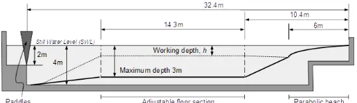
[image:3.612.318.576.400.475.2]Fig. 2: Sketch of the wave basin
Fig. 4: Illustration of the location of the pressure sensors
Configuration of the physical model
The experiments were performed in the wave basin at the University of Plymouth, which features 35 m in length, 15.5m in width and 2.93m in depth, as shown in Fig. 2. Flap wave paddles are installed to generate three-dimensional waves. A simplified FPSO with two ends being semi-circles (0.15m radius) is used in the experiments. The length, width and the height of the FPSO model is 1.2m, 0.3m and 0.3m, respectively, as illustrated in Fig. 3. The temporal variation of surface elevations at various locations in the wave basin and near the FPSO is recorded by 24 wave gauges with sampling frequency of 128Hz. Those near the FPSO are illustrated in Fig. 3. Six pressure sensors are installed near the bow of the FPSO as illustrated in Fig. 4. Pressure sensors P1, P2 and P3 are located at the bow and they are 0.05m above mean free surface (MWL), in line with the MWL and 0.05m below the MWL. The vertical spacing of the sensor groups P4-P6 are the same as P1-P3, but they are located at 45o about the longitudinal axis of the FPSO.
Table 1. Wave parameters for each of the test cases
ID A(m) Tp(s) Hs(m) kA
11BT1 0.06914 1.456 0.077 0.13
12BT1 0.09128 1.456 0.103 0.18
13BT1 0.09363 1.362 0.103 0.21
(a)Side view
[image:4.612.329.559.237.596.2](b)Top view Fig. 5 Sketch of mesh in the qaleFOAM
The focusing waves are generated by using flap wave paddles whose motion is specified by using a 2nd order wavemaker theory, where xf =
13.886m. JONSWAP spectrum is used, where different significant wave heights are considered. The parameters describing the wave conditions are summarized in Table 1.
Numerical configuration
In the numerical wave tank, the size of the FNPT domain is 40m×3m×2.93m with the NS domain size of 5.4m×3m×3.53m. The mesh size in the qaleFoam is 0.025m and time step is 0.0078125s. The time step is adjusted through the fixed Courant number. Different configurations of the domain size, mesh number and absorption zone size are considered in the convergence tests. Fig. 5 illustrates a mesh near the FPSO used by the qaleFOAM. The setups of 50 cells per maximum wave height, 180 cells per peak wave length and the absorption zone of 0.6m are adopted in the following simulation, which are found to be less expensive while can maintain good accuracy.
Fig.6 Wave time history recorded at different gauge positions in the cases without FPSO (case 11BT1)
Wave Generation
[image:4.612.46.298.425.682.2]cases considered here, the wave elevation recorded by Gauge WG1 in the empty-tank test without the FPSO is used to produce the wavemaker motion using the QALE-FEM only. Fig. 6 shows the wave time histories recorded by different wave gauges. As expected, the wave time histories at various locations obtained by the QALE-FEM agree well with the experimental data, demonstrating the effectiveness of the self-correction mechanism used by the QALE-FEM. The wavemaker motion is then employed by the qaleFOAM. The corresponding results are also plotted in Fig. 6 for comparison. It is found that the qaleFOAM results match with the experimental and the QALE-FEM solution in most of the time except for the late stage of the simulation. This may imply that the reflected waves may be re-reflected from the coupling boundary Гc. Although using a larger relaxation zone may minimize the reflection, one may agree that such agreement is acceptable. Similar agreements are also observed for other wave conditions. For clarity, only some results are presented in Fig. 7 for demonstration.
Convergence properties
[image:5.612.348.546.45.247.2]Fig.7 Wave time history recorded at different gauge positions in the cases without FPSO (cases 12BT1 and 13BT1)
Fig. 8 Wave elevation near the FPSO at two different time instants(12BT1)
The simulations of wave diffraction due to the fixed FPSO-like structure are then carried out. In this section, the wave conditions are the same with that in the empty-tank. Fig.8 illustrates a snapshot of the wave elevation near the fixed FPSO at different time instants, where a typical diffraction phenomenon is observed. To sufficiently resolve the wave elevation, especially the pressure distribution and the wave run-up on the structures, the mesh resolution may be much higher than that used in the empty tank test.
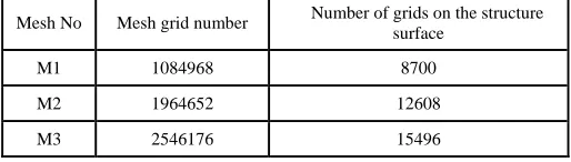
[image:5.612.44.272.247.608.2]To demonstrate the convergence of the qaleFOAM for such problems, different mesh resolutions in the NS domain of the qaleFOAM are considered and summarized in Table 2. The mesh resolution in the QALE-FEM domain remains the same, i.e. 0.03m in the longitude direction on the free surface, and the mesh size exponentially increases from the free surface to the tank bottom; in the transverse direction (parallel to the wavemaker), only 4 cells are used.
Table 2: Computational mesh in the NS domain of qaleFOAM
Mesh No Mesh grid number Number of grids on the structure surface
M1 1084968 8700
M2 1964652 12608
M3 2546176 15496
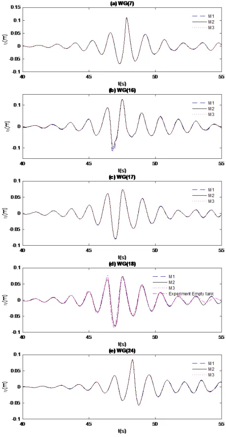
[image:5.612.320.577.483.556.2]Fig. 9 Wave elevation recorded at different wave gauges in Case 13BT1
Not only in Case 13BT1, but also in other two cases (some results are shown in Fig. 11 and Fig. 12 for demonstration), it is found that the results obtained by using M2 and M3 lead to very close results for both wave elevation and pressure. This does not only demonstrate a good convergent property of the qaleFOAM, but also justifies that M2 is sufficient for obtaining the convergent solution. It should be noted that
in the above tests, the Courant number Co (Co=(uΔ𝑡𝑡)/ Δ𝑥𝑥, where Δ𝑥𝑥 is the mesh size) is a constant value, i.e. Co=1. To ensure the convergence of the time step size, a smaller value of Co = 0.5 is used for Case 13BT1 with the mesh M2. As observed, Co=0.5 and Co=1 give almost identical results. Consequently, M2 with Co=1 are applied for this specific working condition. In the further simulations, same convergence tests are conducted for different working conditions.
[image:6.612.45.274.37.480.2]Fig. 10 Time histories of the pressure recorded at different locations in Case 13BT1
[image:6.612.318.570.383.589.2]Fig. 12 Time histories of the pressure recorded at different locations in Case 13BT1
Wave Diffraction due to fixed FPSO
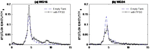
As indicated above, the presence of the FPSO leads to significant diffraction effects on incident waves. Fig. 13 illustrates a comparison of the time history of the wave elevation recorded at WG16 and WG24, corresponding to the bow and the stern of the FPSO, in the cases with and without FPSO. As expected, the diffraction effects considerably amplify the wave elevation at the bow but suppress that at the stern of the FPSO. A further check of the spectrum shown in Fig. 14 indicates that the wave components near the peak frequency (𝜔𝜔𝑝𝑝= 4.3𝑠𝑠−1Tp = 1.456s,) are influenced most significantly. In particularly at the bow, a significant amplification of high frequency components (𝜔𝜔> 7𝑠𝑠−1) are identified. A similar amplification is also found in the case with lower wave height, i.e. Case 11BT1. Some results are shown in Fig. 14 and Fig. 15. It is found in Fig. 13 that 𝜂𝜂/𝐻𝐻𝑠𝑠 in the FPSO case with Hs = 0.103m (12BT1) is close to the corresponding results with Hs = 0.077m (11BT1). This implies that the nonlinearity may not be strong. The change in the spectra in Figs. 14 and 15 may be dominated by the diffraction effects, which behaves linearly. A similar observation is also found in the case with different incident wave spectrum but with the same significant wave height, i.e. Case 13BT1 (Tp = 1.456 s) for the wave elevation at the bow (Fig. 16(a)). However, a less slight diffraction effect is observed in the stern of the FPSO (Fig. 16(b)).
Computational time
All cases are running in a workstation with Intel Xeon E5-2660 v3 (Intel Corporation, Santa Clara, CA, USA) of a 2.6GHz processor. MPI parallel computing using 8 cores have been performed. The CPU time for the cases with different mesh resolutions are summarized in Table. 3.
Table 3 CPU time of three working conditions with three sets of meshes
Case ID M1 (s) M2(s) M3(s)
11BT1 92005 117982 157723
12BT1 93334 129465 163300
[image:7.612.321.575.46.287.2]13BT1 103561 144992 179983
[image:7.612.320.569.333.414.2]Fig. 13 Comparison of time history of wave elevation in the cases with and without FPSO (Case 12BT1 and Case 11BT1, Tp = 1.456s)
[image:7.612.319.568.462.545.2]Fig. 14 Comparison of amplitude spectrum of wave elevation in the cases with and without FPSO (Case 12BT1, Hs = 0.103m, Tp = 1.456s)
Fig. 15 Comparison of amplitude spectrum of wave elevation in the cases with and without FPSO (Case 11BT1, Hs = 0.077m, Tp = 1.456s)
[image:7.612.319.567.581.664.2]CONCLUSIONS
This paper presents a numerical investigation on the interaction between focusing wave and a fixed FPSO-like structure by using a hybrid model, i.e., the qaleFOAM. Due to fact that the work is done for the CCP-WSI blind test workshop, only the convergent properties of the hybrid model and the accuracy of the wave generation technique are demonstrated here. The results show that the hybrid model qaleFOAM can well reproduce the water waves by using the self-correction wavemaker mechanism. Meanwhile, good convergence property is also observed. More results will be discussed in the conference.
ACKNOWLEDGEMENTS
The authors at City, University of London gratefully acknowledge the financial support of EPSRC projects (EP/M022382, EP/N006569 and EP/N008863). All authors acknowledge the support of UKIERI-DST project (DST-UKIERI-2016-17-0029)
REFERENCES
Adcock, TAA, Taylor, PH, Yan, S, Ma, QW, and Janssen, PAEM. (2011). “Did the Draupner wave occur in a crossing sea?”.
Proceedings of the Royal Society A: Mathematical, Physical and Engineering Sciences, 467(2134), 3004-3021
Chen, LF, Zang, J, Hillis, AJ, Morgan, GCJ, and Plummer, AR (2014). “Numerical Investigation of Wave-structure Interaction using OpenFOAM”, Ocean Engineering, 88, 91-109.
Ferrer, PM, Causon, DM, Qian, L, Mingham, CG, and Ma, ZH (2016). “A multi-region coupling scheme for compressible and incompressible flow solvers for two-phase flow in a numerical wave tank”, Computers & Fluids, 125, 116-129.
Grilli, ST, Guyenne, P, and Dias, F. (2001). “A fully non-linear model for three-dimensional overturning waves over an arbitrary bottom,”
International Journal for Numerical Methods in Fluids, 35(7), 829-867. Hildebrandt, A, and Sriram, V. (2014). “Pressure distribution and vortex shedding around a cylinder due to a steep wave at the onset of breaking from physical and numerical modeling,” Proceedings of the 24th International Offshore and Polar Engineering Conference (ISOPE), Vol.3, 405-410, Busan, Korea.
Kashiwagi, M. (2000). “Nonlinear simulations of wave-induced motions of a floating body by means of the mixed Eulerian– Lagrangian method.” Proceedings of the Institution of Mechanical Engineers. Part C, Journal of Mechanical Engineering Science, 214,841–855. Lind, SJ, Xu, R, Stansby, PK, and Rogers, BD. (2012), “Incompressible
Smoothed Particle Hydrodynamics for free surface flows: A generalised diffusion-based algorithm for stability and validations for impulsive flows and propagating waves,” J. Comp. Phys., 231, 1499- 1523.
Longuet-Higgins, M, and Cokelet, E. (1976). “The Deformation of Steep Surface Waves on Water. I. A Numerical Method of Computation,”
Proceedings of the Royal Society of London. Series A, Mathematical and Physical Sciences, 350(1660), 1-26.
Ma, QW. (2005). “Meshless local Petrov-Galerkin method for twodimensional nonlinear water wave problems.” Journal of Computational Physics, 205(2), 611-625
Ma, QW, and Yan, S. (2009). “QALE-FEM for numerical modelling of non-linear interaction between 3D moored floating bodies and steep waves”, International Journal for Numerical Methods in Engineering, 78, 713-756.
Ma, QW, Yan, S, Greaves, D, Mai, T, and Raby, A. (2015). “Numerical and experimental studies of Interaction between FPSO and focusing waves,” The Twenty-fifth International Ocean and Polar Engineering
Conference, Kona, Hawaii, USA.
Schäffer, HA. (1996). “Second order wavemaker theory for irregular waves,” Ocean Engineering, 23(1), 47-88.
Sriram, V, and Ma, QW. (2012). “Improved MLPG_R method for simulating 2D interaction between violent waves and elastic structures.” Journal of Computational Physics, 231(22), 7650-7670. Sriram, V, Schlurmann, T, Schimmels, S. (2013). “Focused wave
evolution using linear and second order wave maker theory in intermediate water depth,” Proceedings of the 23rd (2013) International Offshore and Polar Engineering Conference (ISOPE), Vol.3,897-904, Anchorage, USA.
Tanizawa, K, and Minami, M. (2001). “Development of a 3D-NWT for simulation of running ship motions in waves.” International
Workshop on Water Waves and Floating Bodies, Hiroshima, Japan.
Tromans, PS, Anaturk, AR, and Hagemeijer, P. (1991). “A new model for the kinematics of large ocean waves-application as a design wave,” The First International Offshore and Polar Engineering Conference. International Society of Offshore and Polar Engineers, Edinburgh, UK. Wu, GX, Eatock-Taylor, R. (2003). “The coupled finite element and boundary element analysis of nonlinear interactions between waves and bodies.” Ocean Engineering, 30,387–400.
Yan, S, and Ma QW. (2007). “Numerical simulation of fully non-linear interaction between steep waves and 2D floating bodies using the QALE-FEM method.” Journal of Computational Physics, 221:666– 692.
Yan, S, and Ma, QW. (2010). “Numerical simulation of interaction between wind and 2D freak waves.” European Journal of Mechanics, B/Fluids, 29(1), 18-31.
Yan, S, Ma, QW, Sriram, V, Qian, L, Ferrer, PJM and Schlurmann, T. (2015). “Numerical and Experimental Studies of Moving Cylinder in Uni-directional Focusing Waves”, The Twenty-fifth International
Ocean and Polar Engineering Conference, Kona, Hawaii, USA.
Zang, J, Taylor, PH, and Morgan, GCJ. (2010) “Steep wave and breaking wave impact on offshore wind turbine foundations - ringing revisited,”
25th International Workshop on Water Waves and Floating Bodies, Harbin, China.
Zheng, X, Ma, QW, and Duan, WY. (2014). “Incompressible SPH method based on Rankine source solution for violent water wave simulation.” Computational Physics, 276, 291-314.