AI EDAM
http://journals.cambridge.org/AIE
Additional services for
AI EDAM:
Email alerts: Click here
Subscriptions: Click here
Commercial reprints: Click here
Terms of use : Click here
SPIDA: Abstracting and generalizing layout design cases
D. MANFAAT, A.H.B. DUFFY and B.S. LEE
AI EDAM / Volume 12 / Issue 02 / April 1998, pp 141 159 DOI: null, Published online: 08 September 2000
Link to this article: http://journals.cambridge.org/abstract_S0890060498122060
How to cite this article:
D. MANFAAT, A.H.B. DUFFY and B.S. LEE (1998). SPIDA: Abstracting and generalizing layout design cases. AI EDAM, 12, pp 141159
Request Permissions : Click here
SPIDA: Abstracting and generalizing layout design cases
D. MANFAAT,1,2A.H.B. DUFFY,1andB.S. LEE2
1CAD Centre, Department of Design, Manufacture and Engineering Management, University of Strathclyde,
75 Montrose Street, Glasgow G1 1XJ, Scotland, UK
2Department of Ship and Marine Technology, University of Strathclyde, 100 Montrose Street, Glasgow G4 0LZ, Scotland, UK
(ReceivedJune 27, 1997;RevisedOctober 17, 1997;AcceptedNovember 10, 1997)
Abstract
Abstraction and generalization of layout design cases generate new knowledge that is more widely applicable to use than specific design cases. The abstraction and generalization of design cases into hierarchical levels of abstractions provide the designer with the flexibility to apply any level of abstract and generalized knowledge for a new layout design problem. Existing case-based layout learning (CBLL) systems abstract and generalize cases into single levels of abstractions, but not into a hierarchy. In this paper, we propose a new approach, termed customized viewpoint—spatial (CV–S), which supports the generalization and abstraction of spatial layouts into hierarchies along with a supporting system, SPIDA (SPatial Intelligent Design Assistant).
Keywords: Abstraction; Generalization; Machine Learning; Pattern Matching; Spatial Layout Design
1. INTRODUCTION
The utilization of spatial layout design experience can be con-sidered as being a key part of the spatial layout design pro-cess in that a form of design experience is used or modified to produce a new design solution (Foz, 1973; Akin, 1978; Jones, 1980). Here, design experience refers to specific past spatial layout design cases and abstract and generalized knowledge generated from these cases by the processes of ab-straction and generalization. Abab-straction can be considered as being a process of reducing the complexity of an object (Si-mon, 1981; Darden, 1987; Coyne & Flemming, 1990; Ox-man, 1990; Hoover et al., 1991). Generalization is defined as being an inference process or learning from examples, aim-ing to generate concepts whose descriptions are more gen-eral than those of the examples (Cohen & Feigenbaum, 1982). Thus, a basic distinction made in this paper is that abstrac-tion reduces detail but can be applied to a single case, whereas generalization generates new knowledge from more than one case and thus represents more widely applicable knowledge. Generalization of past spatial layout design cases into
hi-erarchical levels of abstractions provides the designer with
the flexibility to apply any level of abstract and generalized knowledge to a new design problem (Duffy, 1993; Duffy & Kerr, 1993). It also supports an efficient search for the best matched cases because it provides a reduced search space of the cases (Oxman, 1990). That is, the search is directed from the higher to lower levels of abstract and generalized knowledge in the hierarchy rather than to the cases. Simi-larly, the abstraction of a single case into hierarchical
lev-els of abstractions provides the designer with the flexibility
to choose any level of abstraction that he or she needs for generating a new design solution.
In the field of spatial design, existing case-based layout learning (CBLL) systems support the abstraction and gen-eralization of layout design cases by learning from the cases (Coyne et al., 1989; Coyne & Postmus, 1990). However, they do not generalize design cases into a hiearchy, but rather generalize the cases into a single abstract level. Conse-quently, the designer is restricted to using the abstract and generalized knowledge of only one level of abstraction of the cases. In addition, when searching for the best matched cases, these systems can only reduce the search space by considering a single level of abstraction. Thus, guided search-ing through abstract hierarchies in a top-down manner is prohibited. The systems also do not abstract a single case into a hierarchy according to the designer’s needs.
In this paper, we present a new approach, called the
cus-tomized viewpoint—spatial (CV–S), which is proposed to
Reprint requests to: D. Manfaat, CAD Centre, Dept. of Design, Manu-facture and Engineering Management, University of Strathclyde, 75 Mon-trose Street, Glasgow G1 1XJ, Scotland, UK. Tel: (144) 141-552-4400; Fax: (144) 141-552-3148; E-mail: [email protected]
Copyright © 1998 Cambridge University Press 0890-0604/98 $12.50
overcome the above limitations that existing CBLL sys-tems have. It builds on the work of Duffy and Kerr, who advocate that viewpoints should be customized to suit par-ticular designers’ needs (Duffy & Kerr, 1993; Kerr, 1993). Thus, the CV–S approach supports the effective utilization of spatial layout design experience by generalizing past spa-tial layout design cases and abstracting a single case into hierarchical levels of abstractions according to the design-er’s needs. In addition, the realization of this approach in a computer system is presented.
To introduce the CV–S approach and its realization in a computer system, the existing CBLL systems are briefly re-viewed in Section 2. Aspects of pattern matching as a key process of generalization of layouts are discussed briefly in Section 3. The CV–S approach is presented in Section 4, followed by the key descriptions of techniques used to im-plement the approach in Section 5. The imim-plementation of the CV–S approach in a computer system, SPIDA, is pre-sented in Section 6. An evaluation of the SPIDA system in the light of dimensions of learning in design as defined by Grecu and Brown (1996) is presented in Section 7. Finally, a conclusion of the work presented in this paper is pre-sented in Section 8.
2. EXISTING CBLL SYSTEMS
Systems developed by Coyne et al. (1989) and Coyne and Postmus (1990) are examples of the existing CBLL sys-tems. Both systems use neural networks to represent and generalize past spatial layout design cases. In general, the systems learn a set of patterns of design cases and acquire general descriptions of the patterns. When presented with a partial input pattern, the systems produce the output pattern by completing the input pattern, using the acquired general descriptions. Consequently, the result of this generalization process is a single-level abstraction of the design cases in the form of the output pattern.
In the above systems, pattern matching is involved when matching a partial input pattern against a set of learned pat-terns, to produce an output pattern that represents the general descriptions of the learned patterns. Thus, pattern matching is a key process of the generalization process and one that has received little attention in spatial layout design.
3. OVERVIEW OF PATTERN MATCHING
Pattern matching can be defined simply as the activity of matching patterns with the aim of finding similarities be-tween them for the purpose of recognition and/or retrieval of similar patterns. One field where pattern matching is in-volved is pattern recognition (Fu, 1976). In this field, pat-tern matching is used to decide how closely an input patpat-tern “fits” a class of patterns, thus classifying the input pattern into a predetermined class. It also plays a vital role in de-sign, where the process often is greatly assisted by identi-fying, retrieving, and then modifying appropriate past design
cases, and generalizing the cases, with the implied benefit of being able to utilize relevant past experience (Maher & Zhao, 1987; Duffy & Kerr, 1993).
A number of approaches with their diverse techniques have been developed in pattern matching. The three main aspects that characterize a pattern matching technique are pattern
classes, degree of similarity, and matching methods. These
three main aspects are addressed briefly in the following three subsections.
3.1. Pattern classes
Pattern classes refer to the classes of patterns that are used
in the pattern matching process. The four basic classes of patterns are geometric patterns, topological relations,
dis-tributed patterns, and semantic/symbolic patterns (see
Fig-ure 1). Patterns in the class geometric patterns, for example,
point sets, dimensional graphs, and drawings, are
repre-sented in coordinate systems. The class topological rela-tions is represented as a network or a graph made up of vertices, edges, and faces. This network or graph represents connections of the elements of a pattern. Patterns in the class distributed patterns, for example, spatial patterns, spatial
relationship patterns, and graphical patterns, are
distrib-uted across a matrix of grid units or of pixels in computer monitors. Examples of the class semantic/symbolic pat-terns are text and symbols (such as diagrams, icons, etc.).
3.2. Degree of similarity
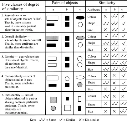
The degree of similarity reflects the amount of match be-tween patterns of matched objects. There are different ap-proaches to defining the degree of similarity that may exist between matched objects. For example, Smith (1989) clas-sifies the degree of similarity into five classes:
resem-blances, overall similarity, identity, similarity, and part-identity (see Figure 2). In Figure 2, each class is illustrated
with three examples, each showing the relationship be-tween two objects in a pair. The attributes of each object in the pair, such as the color, shape, and dimension, are used to compare the objects.
The class resemblances is an all-encompassing class of similarity that includes the other four classes and is, there-fore, similarity at its most “undisciplined”—unconstrained and unspecified (Smith, 1989). The classes overall
ity and identity are concerned with a whole-object
similar-ity that takes into account all of an object’s characteristics at once, and no particular attributes are emphasized. Over-all similarity is defined for objects that are discriminably different but also highly similar overall, while identity is concerned with objects that are the same. The classes
part-similarity and part-identity are concerned with the
Fig. 1. Four basic classes of patterns (Manfaat et al., 1996).
[image:4.612.101.507.334.724.2]are identical in their particular attributes or share common particular attributes.
3.3. Matching methods
The underlying methodology on which matching processes are based can also have significant effects on the character-istics of pattern matching techniques, and thus is an impor-tant issue when considering adoption for specific applications. In design, different matching methods are used. An example is neural networks used in the CBLL systems mentioned in Section 2. The method is used to match a partial input pattern against a set of learned patterns of layout design cases. An-other method is symbolic pattern matching, which is, in most cases, used in case-based design (CBD) systems (Bareiss, 1991; Kolodner, 1993) to match design attributes. Other meth-ods are bitmap matching and graph-theoretic algorithms, such as those used in a CBD system called FABEL (Voß et al., 1994). The former is used to match images of layout design cases, while the latter are used to match topological relations of the furniture of room design cases.
4. CUSTOMIZED VIEWPOINT— SPATIAL APPROACH
In this paper, we present a new approach to abstracting and generalizing layout design cases called customized
viewpoint—spatial (CV–S). This approach is aimed to
over-come the limitations that existing CBLL systems have. It is based on the customized viewpoint (CV) approach (Duf-fy & Kerr, 1993; Kerr, 1993), which advocates the abstrac-tion and generalizaabstrac-tion of specific experiential design knowledge into appropriate viewpoints according to the de-signer’s needs. That is, the designer can select particular
viewpoints for abstraction and generalization. The CV ap-proach focuses on numerical design. Our CV–S apap-proach is concerned with spatial design.
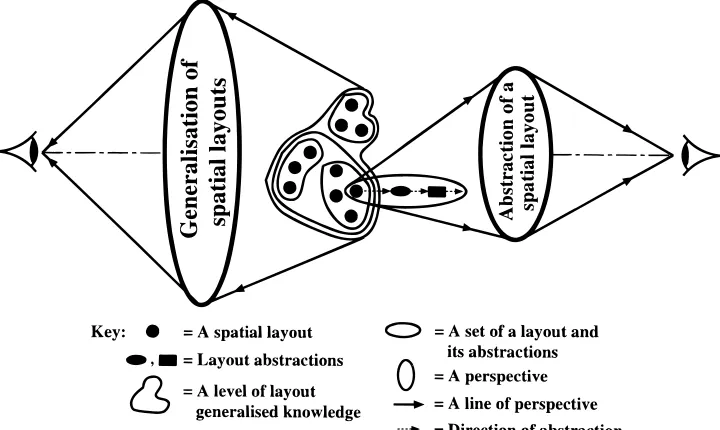
The CV–S approach has two separate parts:
generaliza-tion of layouts and abstracgeneraliza-tion of a single layout into
hier-archical levels of abstractions, based on different viewpoints, according to the designer’s needs (see Figure 3). The gen-eralization part focuses on layouts and their different levels of generalized knowledge, while the abstraction part fo-cuses on a layout and its levels of abstractions. In the case of abstracting a layout, the designer can browse over the set of layouts and select a layout for the abstraction into a hi-erarchy. The designer then can utilize any level of a layout’s abstractions in the hierarchy for a new design problem.
4.1. Generalization of spatial layouts
[image:5.612.129.489.504.719.2]In the synthesis stage of original design, that is, design that involves elaborating original solution principles for the de-sign problem to form a new dede-sign product (Pahl & Beitz, 1988), the design solution generated is based on previously defined design attributes. In spatial design, the designer of-ten uses diagrams (e.g., “bubble diagrams”) and sketches to help him or her generate initial layout design solutions (Jones, 1963). In “diagramming,” the designer draws the di-agrams of adjacencies between spaces that result in the to-pological pattern of the layout. While in sketching the designer draws the spaces, each with its geometric shape, based on the diagrams of spatial adjacencies, thus combin-ing the topological pattern and geometric shape of the lay-out. Consequently, in a spatial layout design process that directly utilizes past layout solutions or their abstractions as the initial solution, there are two main advantages:
•
the designer’s task of generating the solution can be reduced; and•
the designer can be provided with a suitable topologi-cal pattern or combination of topologitopologi-cal pattern and geometric layout.As addressed in Section 2, by using neural networks, the existing CBLL systems are able to generalize patterns of layout designs, for example, spatial patterns and spatial ad-jacency patterns. Given a partial input pattern, the systems complete this pattern using the general descriptions ac-quired from a set of learned patterns. However, the draw-backs of neural networks are that a change to the input pattern (e.g., due to rotation, scaling, translation, etc.) should result in a mismatch of the output pattern (Manfaat et al., 1996), and that they are essentially “black boxes,” in that the knowl-edge they contain is not explicit with the same clarity, for example, as symbolic representations (e.g., rules in an ex-pert system) (Coyne et al., 1989).
Considering the drawbacks of neural networks and the advantages of using past layout solutions, we present two approaches to generalizing layouts into a hierarchy based on two different viewpoints: topology (similarities in spa-tial adjacencies) and a combination of topology and geom-etry (similarities in spatial adjacencies and geometric shapes), respectively. These two approaches, and a number of key issues that should be taken into account if either of these two approaches is to be pursued, will be discussed briefly in the following three sections.
4.1.1. Topological generalization
In this paper, the word topology refers to adjacencies be-tween the spaces of a layout in terms of the nature of the spaces. The name of a space expresses the nature of the space. Two spaces, for example, galley1 and galley2, have the same
nature, that is, a galley. In the nature of a space, there is an inherent function that allows analogies. For example, a gal-ley and a pantry are analogous to spaces used for the prep-aration and cooking of food.
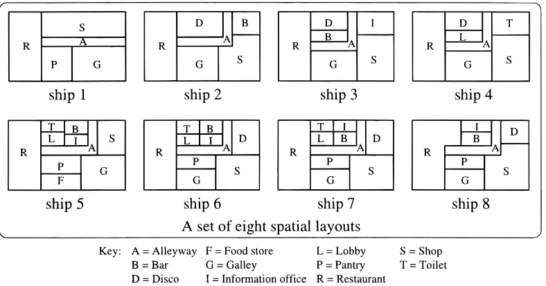
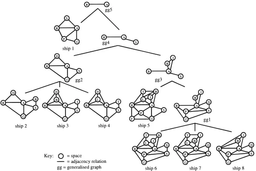
The topology of a layout can be represented as an adja-cency graph. As an example, consider a set of eight spatial layouts of the catering decks of passenger ships given in Figure 4. When generalizing this set based on topology, the hierarchy of adjacency graphs given in Figure 5 may rep-resent the result of this generalization. The grouping of the layouts and their abstractions, respectively, are based on sim-ilarities in these graphs, that is, the number of the same ad-jacency relations that preserve the corresponding nodes (spaces) between the graphs. For example, at the lowest level of the hierarchy, ships 6, 7, and 8 share the maximum num-ber of adjacency relations that preserve the corresponding nodes, as compared to the graphs of the other ship layouts. Therefore, the graphs of these three ships are generalized into a generalized graph, gg1, one level above them. The process of generalization continues to the higher levels un-til the overall hierarchy of adjacency graph abstractions is generated.
4.1.2. Combined topological and geometric generalization
[image:6.612.108.502.518.725.2]When generalizing spatial layouts based on the combina-tion of the topological patterns and geometric shapes of the layouts, topological pattern matching between the layouts is initially carried out. This is because, as discussed previ-ously, in the spatial design process the designer often gen-erates the initial solution based on “bubble diagrams” and sketches. The diagrams represent patterns of connectivity (topology) between spaces. In sketching the layout the to-pology is also represented, in addition to other features, such as shapes, sizes, and so on. Thus, topology is one of the
main features of a layout that initially should be taken into account when generating the solution. Once the correspond-ing spaces of each of the matchcorrespond-ing layouts have been de-fined, geometric shape matching then is applied to each of these corresponding spaces. The result of the matching of each of these corresponding spaces gives a measure of the similarity between the spaces. Accumulating the measures of similarity of all of the corresponding spaces gives an over-all measure of the similarity between the matched layouts. The clustering of the layouts and their abstractions, respec-tively, is based on their measures of similarity.
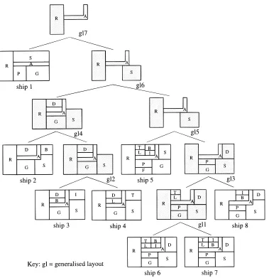
As an example, when generalizing the set of layouts in Figure 4 based on the combination of topological patterns and geometric shapes of layouts, we may have a hierarchy of generalized layouts as shown in Figure 6. In this figure, in terms of adjacency graphs, the layouts of ships 6, 7, and 8 are similar (see Figure 5). However, in terms of geometric shapes, the layouts of ships 6 and 7 are more similar than if each of these layouts is compared to the layout of ship 8. That is, all of the shapes in ships 6 and 7 are the same, but in ship 8 the restaurant (R) and shop (S) are different. There-fore, the layouts of ships 6 and 7 are generalized into a gen-eralized layout, gl1, one level above them. The generalization process continues to the higher levels until the overall hi-erarchy of layout abstractions is generated.
4.1.3. Key issues
Realizing these two approaches to learning from past de-signs, within a computer support environment, gives rise to a number of key issues:
•
How to represent the layouts? Representations of thelayouts should support the processes involved, such as pattern matching, clustering, generalization, and re-trieval of the layouts and their abstractions. For exam-ple, closed polygons may be used to represent the geometric shape or pattern of a layout. These polygons may be transformed into a different representation in order for a process, for example, pattern matching, to be carried out.
•
How to pattern-match the layouts? To generalize the [image:7.612.60.565.57.394.2]layouts, we need to cluster them into groups. To clus-ter them, we need to patclus-tern-match one layout to an-other. For example, given two geometric patterns to match, the pattern-matching process should be carried out in such a way that the result of matching is as ac-curate as possible. Further, if there is a change to ei-ther or both of the patterns (e.g., due to rotation, scaling, translation, etc.), the accuracy of matching should not be affected. That is, the matching process should be robust.
•
How to measure similarities between the layouts?Matching layouts results in a degree of similarity, such as an overall or a part similarity, between them. It is carried out by comparing the parts and/or attributes of one layout with those of another. For example, in match-ing two graphs representmatch-ing two topological patterns of layouts, the measuring of similarities between the graphs is carried out by finding the correspondences between the nodes of one graph and those of another graph, which preserve the correspondences between the links of the graphs.
•
How to cluster similar layouts? Based on the measuresof similarities between the layouts, the layouts can be clustered into groups. The clustering should be done in such a way that the layouts that have a higher degree of similarity should be clustered in the same group. The groups of the layouts should further be able to be clus-tered into higher level groups representing abstrac-tions of the layouts.
•
How to generalize the layouts into a hierarchy? Givenclusters of layouts or abstractions, it should be possible
to generalize the layouts or abstractions in each cluster to generate the abstract and generalized (i.e., learned) knowledge. This leads to the generalization of layouts into a hierarchy. In each level of generalization, the gen-eralization process is carried out by preserving the com-mon parts and/or attributes of the layouts or abstractions and neglecting the other parts and/or attributes that are significantly different. For example, in abstracting the ad-jacency graphs of layouts, the corresponding nodes (spaces) that have the correspondences of adjacency re-lations are preserved, while the other nodes are dropped. It also should be noted that different hierarchies can be generated. This is because when matching the topolog-ical patterns of two layouts in both kinds of generaliza-tions, for example, there can be different sets of corresponding spaces that have the same number of ad-jacency relations between the spaces. This means that dif-ferent clusters and hence difdif-ferent generalizations may be generated.
[image:8.612.117.496.55.446.2]•
How to search, match, and retrieve similar layouts given an input layout? To retrieve layouts similar to a giveninput layout, we need to search the layouts and their abstractions and match the input against them. The in-put given by the designer should be represented in such a way that these searching and matching processes can be carried out. Once the matching layouts or abstrac-tions are found, it should be possible to retrieve the layouts and/or abstractions.
•
How to update the hierarchical abstractions of layouts when new layouts are added? This involvesaugment-ing the hierarchical abstractions of layouts by addaugment-ing new layouts. Will the added layouts be accommodated into particular clusters of layouts/abstractions as the new instances of these clusters? Or will these hierarchical abstractions be regenerated by including the added lay-outs?
By addressing such issues, a resulting system will be able to learn, and make explicit, previously implicit knowledge through the generation of abstract hierarchies and general-ized topological and shape knowledge.
4.2. Abstraction of a spatial layout
A hierarchical approach to layout design problems has been suggested by various design researchers and used in design practice (Eastman, 1973; Pfefferkorn, 1975; Carlson & Fire-man, 1987; Cort & Hills, 1987). In this approach, a layout is generated hierarchically from groups of spaces (abstract) to smaller groups (more specific) and so on until the layout is completely determined. In other words, the design pro-cess proceeds from an abstract to a more detailed layout, forming hierarchical levels of layout abstractions. With such hierarchical levels of abstractions, design can be carried out at each level of abstraction. For example, in designing a building layout, design can be carried out at the levels of floors, groups of functional spaces, individual spaces, and furniture within the spaces. Abstraction of a past spatial out into a hierarchy therefore provides the designer with lay-out abstractions with which he or she can carry lay-out his or her design at any level.
In the abstraction of a layout, learning is involved when generalizing parts of the layout that have common aspects or attributes. For example, when abstracting a building lay-out from the level of individual spaces to that of the groups of functional spaces, individual spaces with the same func-tions are generalized, forming groups of functional spaces. Based on the importance of abstraction in design as ad-dressed above, in the CV–S approach, the abstraction of a layout into a hierarchy based on the designer’s needs is pre-sented. That is, the abstraction is based on particular as-pects or viewpoints that the designer wishes to focus on. In the spatial design process, when generating the design so-lution, the designer applies some design features, for exam-ple, the functions, sizes, shapes of and degree of importance of adjacencies between the spaces, and considerations, for example, the grouping of spaces based on their functions.
To provide the designer with different perspectives of the abstraction, four viewpoints have been defined in the CV–S approach: area (the areas of spaces), function (the functions of spaces, e.g., food preparation, store, shop), type (the class of spaces, e.g., private, public, and circulation), and
close-ness rating (the degree of importance of adjacencies
be-tween spaces). Figure 7 illustrates the abstraction of a layout based on these four viewpoints. The initial layout has spaces denoted with letters from a to s.
In Figure 7, in the area viewpoint where the abstraction starts, for example, with spaces whose area are minimum, on the first level of abstraction spaces e, f, and g, and h, i, j, k, l, and m have been abstracted into two abstract spaces: (e f g) and (h i j k l m), respectively. On the next level of straction, spaces n and o, and p, q, r, and s have been ab-stracted into two more abstract spaces: (n o) and (p q r s), respectively.
In the function viewpoint, the abstraction of the layout is based on the adjacent spaces whose functions are the same. For example, spaces h, i, j, k, l, and m have the same func-tion: 1. Therefore, on the first level of abstraction they are abstracted into an abstract space whose function is 1.
In the type viewpoint, the adjacent spaces are abstracted into classes to which the spaces belong. These classes may be termed with different names, such as private, public, and circulation areas. For example, in a house the types of the bedroom and dining room may be called, say, private areas; thus, if they are adjacent, they can be abstracted into one larger space, private area. In Figure 7, spaces 2, 3, 4, and 5, for example, have the same space type, that is, B. Conse-quently, when abstracting these spaces, an abstract space whose type is B is generated.
In the closeness rating viewpoint, the abstraction of the layout is based on the degree of closeness (the importance of adjacencies) between the spaces based on a particular as-pect, for example, ease of movement, visual communica-tion, aural communication. The higher the degree, the more important the adjacency between them. Therefore, the ab-straction starts from the spaces with the highest degree of closeness. For example, in Figure 7, on the first level of abstraction, spaces h, i, j, k, l, and m, and p, q, r, and s have been abstracted into two abstract spaces based on the high-est degree of closeness.
Like the generalization of layouts, the abstraction of a layout gives rise to several key issues that need to be taken into account. These key issues are outlined briefly as follows:
•
How to represent the layout? Representations of thelayout should support the abstraction processes based on four viewpoints: area, function, type, and closeness
rating. For example, for the abstraction based on area,
each space of the layout should be geometrically rep-resented, including its coordinate points, dimensions, and area.
•
How to abstract the layout? This involves determiningon the four viewpoints and how the processes are to be carried out.
•
How to generate hierarchical abstractions of the lay-out? It should be possible for hierarchical abstractionsof the layout to be generated, so that the designer can utilize any level of abstraction that he or she wishes.
5. IMPLEMENTATION TECHNIQUES FOR THE CV–S APPROACH
In this section, techniques used to implement the CV–S ap-proach within a computer support environment are briefly described. They are divided into two parts, following the two parts of the CV–S approach: the generalization of lay-outs and the abstraction of a layout.
5.1. Generalization of layouts
The techniques used to generalize layouts consist of those for pattern-matching and clustering and generalizing lay-outs. As for pattern-matching, the use of the symbolic method does not directly support the generalization of the topolog-ical patterns and the combination of the topologtopolog-ical pat-terns and geometric shapes of layouts. This method currently is used to match symbolic representations of layouts, that is, design attributes, rather than layout solutions in the form
of layout drawings. The use of neural networks has draw-backs, as addressed in Section 4.1.
Considering the above drawbacks, we adopt techniques of topological and geometric pattern-matching, that is, the “association graph technique” (Ballard & Brown, 1982) and “planar shape matching” (Leu & Huang, 1988), respec-tively. We recognize that there are more recent techniques of these kinds of pattern-matching (see, for example, Hanyu et al., 1992; DellaCroce & Tadei, 1994; Corno et al., 1995 for topological pattern-matching, and Niblack & Yin, 1995; Cohen & Guibas, 1997 for geometric pattern-matching). However, some of the techniques are application-specific and some others have similar properties as, but do not nec-essarily improve, the techniques we adopt. The techniques we adopt are more generic, more basic, and thus more ap-plicable to different problems of these kinds of matching. In addition, in the implementation of the pattern-matching parts of the CV–S approach, these techniques work appropriately, in that there are no significant problems with time complexity of the pattern-matching process and the techniques are capable of producing good results.
The application of the adopted techniques provides an ac-curate matching result, since they can define the minimum measure of the difference between topological and geomet-ric patterns. In other words, the maximum preservation of the complete information regarding matching topological or geo-metric patterns can be achieved. The “association graph
[image:10.612.84.525.59.351.2]nique” is used as part of the techniques for topological generalization. The combination of this technique and the “pla-nar shape matching” is used as part of the techniques for com-bined topological and geometric generalization. These two techniques are briefly described in Sections 5.1.1 and 5.1.2. As for clustering and generalizing layouts, we are cur-rently investigating, developing, and attempting to imple-ment existing techniques within a computer system to evaluate the CV–S approach.
5.1.1. Association graph technique–based topological pattern matching
The “association graph technique” employs a data struc-ture called an “association graph” and a “clique-finding al-gorithm” (Ballard & Brown, 1982). The technique is able to find all of the isomorphisms (similarities) between the
subgraphs of a graph and the subgraphs of another graph.
Thus it allows the “best match” between two graphs to be defined, as compared to techniques for defining graph iso-morphism between two graphs that aim to find an exact sim-ilarity between the graphs where nodes or arcs must not be missing from one or the other graph.
An “association graph” is a graph whose nodes are pairs of nodes of two graphs of matched layouts, which have sim-ilar properties, and edges connect the graph’s nodes that rep-resent compatible assignments. The “best match” between the two graphs can be defined from the “association graph.” This is achieved by finding the largest set of node corre-spondences in the association graph that are all mutually compatible under the relations. This means finding the larg-est totally connected set of nodes, which is termed a clique. The “clique-finding algorithm” can find cliques with the larg-est number of nodes.
5.1.2. Planar shape matching
The “planar shape matching” technique combined with the “association graph” is used for the combined topologi-cal and geometric pattern matching. In this combined form of matching, the “association graph technique” described above initially is applied to match the topological patterns of layouts. The “planar shape matching” technique then is applied to match the shapes of any corresponding nodes (spaces) in the largest clique of nodes resulting from the topological pattern matching. The result of shape matching of each of the corresponding nodes is accumulated to give a measure of the overall shape similarity between layouts.
The “planar shape matching” technique developed by Leu and Huang (1988) is adopted, since it allows the shape rep-resentation and matching to be view-independent. That is, they do not depend on the locations from which the shape is viewed. In the shape representation, the shape is converted into a different representation, which is view-independent. The shape matching or recognition is also view-independent, since the technique allows viewing transformations be-tween shapes to be matched, which make the shape
match-ing or recognition invariant to shape rotation, scalmatch-ing, translation, and skewing.
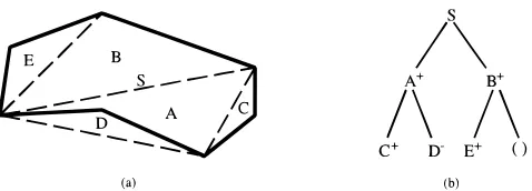
In the above shape matching technique, it is assumed that shapes are planar, their boundaries are closed, and they are without self-crossings. For shape matching, a shape is rep-resented in a binary tree structure whose nodes represent triangles resulting from the partition of the shape. A binary tree is a tree in which every node has two other nodes as its children. A simple example is given in Figure 8. The solid lines of the shape in Figure 8a are the boundary of the shape. The shape is partitioned into triangles, aiming to simplify the shape into a quadrilateral. In the first step of the parti-tion, three triangles (C, D, and E) are formed. Merging the sides of each of these triangles and replacing them with their base lines (the broken lines excluding line S) simplifies the shape into a quadrilateral. The next step of the shape parti-tion is to divide the quadrilateral by line S into two trian-gles: A and B.
Having partitioned the shape in Figure 8a into triangles, a binary tree is constructed (see Figure 8b). The root node of the tree is the dividing line S and the children of S are triangles A and B. Triangles C and D attach to the left and right sides of triangle A, respectively. Therefore, in the tree the two triangles are the left and right children of triangle A. Similarly, triangle E attaches to the left side of triangle B, while there is no triangle on the right side of triangle B. Therefore, in the tree triangle, E is the left child of triangle B, while the right side of triangle B is empty. The “1” and “2” signs indicate whether a triangle lies inside or outside its parent triangle. In addition to these signs, the following three attributes are recorded in each node:
•
The area of the triangle.•
The ratio between the height of the triangle, h, and the base of the triangle, a (i.e., h/a!.•
The ratio between the projection of the left side of the triangle on the base, b, and the base (i.e., b/a!. [image:11.612.320.559.615.701.2]Matching two shapes is realized by comparing the two cor-responding binary tree representations. In this case, the two trees are compared in a top-down fashion, that is, they are compared node by node from the root nodes through to the internal nodes to the leaf nodes. The process of comparing the two trees is carried out according to the breadth-first
search sequence (Leu & Huang, 1988). In each node
com-parison the node (shape) difference with regard to the four attributes of each node is recorded and added to the cumu-lative node difference obtained so far. Thus the result of matching the two trees (shapes) is the final cumulative shape difference, which indicates the value of dissimilarity be-tween the two shapes. This value is numerical, but it can be transformed into a qualitative measure representing a cer-tain degree of similarity. Classes of the degree of similarity between objects as defined by Smith (1989) (see Sec-tion 3.2) can be used for this purpose.
Having matched the shapes of all of the corresponding spaces, the resulting dissimilarity measures are summed up to give a measure of the overall shape dissimilarity between layouts.
5.2. Abstraction of a layout
The abstraction of a layout is realized by merging some or all of the adjacent spaces into merged spaces. In the CV–S approach, spaces are represented in a coordinate system and only rectangular spaces, and polygonal spaces that can be represented as a collection of rectangles, are of concern to us. Consequently, the abstraction based on the above four viewpoints also represents the geometrical abstraction of a layout. For merging spaces and measuring the area of the merged space, we adopt methods of the “geometry of rect-angles” (Preparata & Shamos, 1985), namely, the contour and measure of a union of rectangles. We recognize that there are a few number of more recent techniques for mea-suring the area of and defining the contour of the union of rectangles (see, for example, Widmayer & Wood, 1987; Wu et al., 1988; Datta, 1997). However, they have similar prop-erties as the methods we adopted. In the implementation of the abstraction part of the CV–S approach, the methods we adopt work well. That is, they provide the accurate result of merging spaces in that the contour and area of the merged space can be accurately produced. The use of these meth-ods is combined with the use of a data structure called the
segment tree (Preparata & Shamos, 1985), a rooted binary
tree that represents intervals of integers. This tree is used to represent the ordinates of the vertical sides of rectangles that represent spaces to be merged.
6. SPIDA SYSTEM
To evaluate the CV–S approach, a computer system called SPIDAhas been developed. This system is implemented using Harlequin LispWorks (Common Lisp and CLOS) (The Har-lequin Group Limited, 1994) running on a Silicon Graphics or Sun Sparc workstation. For the processes of generalizing spatial layouts, tools for matching topological patterns of lay-outs and the combined topological patterns and geometric shapes of layouts have been developed. Tools for clustering and generalizing layouts currently are under development. Tools for the processes of abstracting a spatial layout based
on the area, function, type, and closeness rating also have been developed. In this section, we present some experimental re-sults of evaluating the tools that have been developed.
6.1. Topological pattern-matching of layouts
The pattern-matching operation involved in the topological generalization of layout design cases is topological pattern-matching between the cases, aiming to define the similarity in the topological pattern between one design case and an-other. Thus, the operation does not involve matching the cases against an input layout. However, for the purpose of evaluating the “association graph technique” adopted for the topological pattern-matching, in this section we present and briefly discuss some experimental results on matching de-sign cases against input layouts. For the experiment, a set of seven ship layout cases, based on existing designs (see Figure 9), have been stored in the system. A set of three ship layout templates (see Figure 10) also has been set as the input to the pattern-matching process. The term “tem-plate” is commonly used in the field of pattern recognition to mean an input pattern to the pattern-matching process (Hall & Matias, 1993).
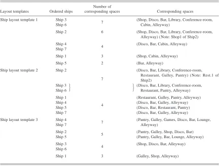
Each space of layout design cases and templates in Fig-ures 9 and 10, respectively, is labeled with the nature of the space. The results of topological pattern-matching between each of the templates and the layout cases are presented in Table 1. In this table, for each template, the layout cases are ordered from the most (on the top) to the least (at the bot-tom) similar to the template. This order of layout cases is based on the resulting number of corresponding spaces. In this case, the higher the number of the corresponding spaces, the more similar is the layout case to the template. If there is more than one layout case that has the same number of the corresponding spaces, they have the same rank. For ex-ample, in Table 1, for ship layout template 1, ships 3 and 6 are placed in the same box and on the top of the order of ship layout cases, since they have the same, highest number (7) of corresponding spaces. The nature of the space of each of the corresponding spaces is also included in the table.
From the above experimental results (see Table 1) it can be observed that the number of corresponding spaces be-tween a layout case and template represents the degree of similarity between them. The degree of similarity may be classified into classes defined by the designer, where each class may have more than one different number of corre-sponding spaces. Classes of degree of similarity as defined by Smith (1989) (see Section 3.2), for example, may be used for this purpose, by assigning a particular class, for exam-ple, the overall similarity, part similarity, and so on, to one or more than one different number of corresponding spaces. Alternatively, each number of corresponding spaces may rep-resent a class of degree of similarity.
cases can be carried out, the clustering of the cases based on the experimental results given in Table 1 may be consid-ered. The clustering is based not only on the similarity in the number of corresponding spaces between each of the layout cases and a template, but also on the similarity in their corresponding spaces. Thus, in relation to the
[image:13.612.119.502.60.597.2]tem-plate, a case with a certain number of corresponding spaces that is the same as that of another case, but with different corresponding spaces, cannot be clustered with the latter case. For example, in the results of matching layout cases against ship layout template 2, ships 3 and 6 can be grouped into a cluster since they have the same corresponding spaces in
relation to the template. On the other hand, although ship 2 has the same number of corresponding spaces as that of the cluster, this ship is not grouped into the cluster, since it has different corresponding spaces from those of the cluster.
Clustering the cases can lead to the generalization of the cases. That is, a cluster is created based on what are com-mon between the cases as its elements. A concept that rep-resents the commonalities between the cases then can be generated. This concept consequently represents the gener-alization of the cases.
6.2. Combined topological pattern and geometric shape matching of layouts
[image:14.612.144.466.61.164.2]For the combined topological and geometric generalization of layout design cases, the pattern-matching operation in-volved is the combination of topological pattern and geo-metric shape matching between the cases. However, as with the topological pattern-matching discussed in Section 6.1, for the purpose of evaluating the combination of the “asso-ciation graph technique” and the “planar shape matching”
Fig. 10. A set of three ship layout templates.
Table 1. Results of topological pattern-matching between each of the layout templates in Figure 10
and the layout cases in Figure 9
Layout templates Ordered ships
Number of
corresponding spaces Corresponding spaces
Ship layout template 1 Ship 3
7 (Shop, Disco, Bar, Library, Conference-room,
Ship 6 Cabin, Alleyway)
Ship 2 6 (Shop, Disco, Bar, Library, Conference-room,
Alleyway) (Note: Shop1 of Ship2)
Ship 4
4 (Disco, Bar, Cabin, Alleyway)
Ship 7
Ship 1 3 (Shop, Cabin, Alleyway)
Ship 5 2 (Bar, Alleyway)
Ship layout template 2 Ship 2
7
(Disco, Bar, Library, Conference-room, Restaurant, Galley, Pantry) ( Note: Rest.1 of Ship2)
Ship 3
Ship 6
J
J
(Disco, Bar, Library, Conference-room, Restaurant, Pantry, Alleyway)
Ship 1
4
(Restaurant, Galley, Pantry, Alleyway)
Ship 4 (Disco, Bar, Galley, Alleyway)
Ship 5 (Disco, Bar, Restaurant, Pantry)
Ship 7 (Disco, Bar, Galley, Alleyway)
Ship layout template 3 Ship 4
7 (Pantry, Galley, Games, Disco, Bar, Lounge,
Ship 7 Alleyway)
Ship 2
5 (Pantry, Galley, Shop, Disco, Bar)
Ship 5 (Pantry, Galley, Bar, Lounge, Alleyway)
Ship 3
4 (Shop, Disco, Bar, Alleyway)
Ship 6
[image:14.612.87.519.388.716.2]technique for this operation, in this section we present and briefly discuss some experimental results on matching lay-out design cases against laylay-out templates. For the experi-ment, the layout cases and templates used in topological pattern-matching (see Figures 9 and 10) are used. The re-sults of matching each of the layout templates against lay-out cases are presented in Table 2. In this table, the laylay-out cases first are ordered based on the number of resulting cor-responding spaces. They then are ordered based on shape dissimilarity measures. The higher the measure, the more dissimilar (less similar) the layout case to the template. The resulting corresponding spaces are the same as those in to-pological pattern-matching (see Table 1).
As with topological pattern-matching, in this kind of pattern-matching, layout cases can be clustered using classes of degree of similarity. One or more than one different num-ber of corresponding spaces can be used as a class of degree of similarity. Classes of degree of similarity as defined by Smith (1989) may be used for clustering the cases. The dif-ference between this kind of pattern-matching and the to-pological pattern-matching is that the clustering is not only based on the same corresponding spaces, but also on the overall shape dissimilarity measures between the spaces. In this case, the clustering may be based on particular ranges of these measures. For the purpose of showing how the clus-tering of the cases can be carried out, the clusclus-tering of the
cases based on the experimental results given in Table 2 may be considered. For example, in the results of matching lay-out cases against ship laylay-out template 2, ships 3 and 6, which have the same corresponding spaces, may be clustered to-gether because the difference between their shape dissimi-larity measures is within the range, for example, 75%. Using clusters of the cases resulting from this kind of pattern-matching, generalization of the cases based on their com-bined topological patterns and geometric shapes can be carried out.
6.3. Abstraction of a spatial layout
As was mentioned in Section 4.2, the abstraction of a spa-tial layout is based on four viewpoints: area, function, type, and closeness rating. The implementation of each of the ab-stractions in the SPIDA system is presented in this section. For all of these abstractions the layout of Ship 5 in Figure 9 is used for the example.
6.3.1. Abstraction based on area
The abstraction of a layout based on area uses the area of each space of the layout as the aspect for the space merging process. In the abstraction process, the system initially finds a space with the minimum area. It then finds any other space whose area is within an area range with respect to the found minimum area. The area range is input by the user. Next, the system merges each of the spaces whose areas are within the area range with its adjacent spaces whose weights (area differences with this space) are minimum. The process con-tinues, resulting in the different levels of abstraction until a layout of a single merged space is achieved. Alternatively, the user can input any number of levels of abstraction ac-cording to his or her needs.
As an example, Figure 11 illustrates the abstraction of the layout of Ship 5 based on area. The original layout of Ship 5 is at the bottom of the figure. The area range that the user input for this abstraction is 100%. The abstraction pro-cess results in four levels of abstractions. It can be seen that on the first level of abstraction spaces 6 and 7 are merged into a merged space labeled MS-177-1, and spaces 9, 10, and 11 are merged into MS-178-1. The label of a merged space is automatically generated by the system, and the last number of the label shows the level of abstraction. At the top level of abstraction (level 4), a single space (MS-183-4) is achieved and displayed at the top of the figure.
6.3.2. Abstraction based on function
In the abstraction of a layout based on function, the layout is abstracted by merging the adjacent spaces whose func-tions are the same. Figure 12 illustrates the abstraction of the layout of Ship 5 based on the functions of the layout spaces. The original layout is at the bottom of the figure. In this lay-out abstraction, spaces MS-129-1 and MS-131-1, for
exam-Table 2. Results of combined topological pattern and geometric
shape matching between each of the layout templates in Figure 10 and the layout cases in Figure 9
Layout templates Ordered ships Number of corresponding spaces Shape dissimilarity measures
Ship layout template 1 Ship 3 7 4.960
Ship 6 7 6.317
Ship 2 6 3.784
Ship 4 4 3.376
Ship 7 4 3.482
Ship 1 3 4.587
Ship 5 2 2.473
Ship layout template 2 Ship 2 7 2.345
Ship 3 7 4.774
Ship 6 7 6.328
Ship 5 4 0.747
Ship 4 4 2.976
Ship 7 4 3.336
Ship 1 4 5.589
Ship layout template 3 Ship 4 7 2.798
Ship 7 7 4.453
Ship 2 5 1.311
Ship 5 5 2.084
Ship 3 4 3.868
Ship 6 4 3.868
[image:15.612.60.299.448.717.2]ple, are the results of merging spaces 5 (the disco), 6 (the bar), 8 (the lounge), 12 (the dance hall), and 13 (the cinema), re-spectively, since they have the same function: leisure. Sim-ilarly, spaces 2 (the pantry) and 3 (the galley) are merged into a merged space, MS-130-1, since their functions are the same:
food preparation. Furthermore, a number of levels of
ab-straction also may be generated by abstracting the layout par-tially. In this case, the user can control the abstraction by inputting parts of the layout (i.e., particular spaces) whose functions are the same. This process can be repeated with the other parts until all of the spaces with the same functions have been merged.
6.3.3. Abstraction based on space type
In the abstraction of a layout based on type, the layout is abstracted by merging the adjacent spaces whose types or groups are the same. Figure 13 illustrates the abstraction of the layout of Ship 5 based on the types or groups of spaces. The original layout is at the bottom of the figure. In this layout abstraction, spaces 1 (the restaurant), 4 (the tax free shop), 5 (the disco), 6 (the bar), and 8 (the lounge), for ex-ample, have been merged into a merged space, MS-136-1, since they can be grouped as the public area. Consequently, the abstraction based on type can be applied to the abstract layout resulting from the abstraction process based on the functions of the spaces. In addition, as in the abstraction of a layout based on the functions of spaces, the abstraction based on space type can be carried out partially and repeat-edly, resulting in abstractions at different levels.
6.3.4. Abstraction based on closeness rating
In the abstraction of a layout based on closeness rating, the layout is abstracted in different levels of abstractions by merging the adjacent spaces starting from the highest
[image:16.612.61.287.62.458.2]close-Fig. 11. Abstraction of the layout of Ship 5 based on area.
[image:16.612.55.346.517.714.2]ness ratings between them. For this abstraction, seven grades of closeness ratings are defined. Of these seven grades, six grades are represented in numbers ranging from 0 to 5, with 0 being not adjacent and 5 being essential. Thus, the higher the grade, the more important the adjacency between spaces. Another grade is denoted with the letter E (exception). This grade is meant here to be the grade of the adjacency be-tween a space for a particular activity, for example, the gal-ley, pantry, and so on, and a space for circulation, for example, the alleyway. In this abstraction, it is assumed that adjacent spaces with the grade E will not be merged, since they are used for different purposes, that is, activities and circulation. However, adjacent spaces whose functions are for circulation will be merged.
Figure 14 illustrates the abstraction of the layout of Ship 5 based on closeness rating. The original layout is at the bottom of the figure. The abstraction process results in five levels of layout abstractions. In the first level of abstrac-tion, for example, spaces 7, 10 (the lobbies), and 14 (the alleyway), and 1 (the restaurant), 2 (the pantry), and 3 (the galley), are merged into two merged spaces, MS-144-1 and MS-145-1, respectively, since the grade of the closeness rat-ing between each of these spaces and another is the highest (5), compared to the other closeness ratings.
7. DIMENSIONS OF LEARNING
In this section, we evaluate the work we presented in the previous sections in the light of dimensions of learning in design defined by Grecu and Brown (1996).
7.1. What can trigger learning?
The motivation behind the development of the SPIDA tem is to improve the ability of layout design learning
sys-tems. Existing CBLL systems generalize layout design cases into single levels of abstractions. They are not able to gen-eralize design cases into a hierarchy. In addition, they do not abstract a layout into a hierarchy. The SPIDA system is able to carry out such generalization and abstraction, thus improving the abilities of the existing CBLL systems. With such improvements, the abstract and generalized knowl-edge of layout designs can be provided in the different lev-els for a new design session.
In the CV–S approach, learning is triggered by the de-signer’s need to learn about the domain, domain explora-tion (Duffy et al., 1995), or acquire knowledge for a new design problem. The approach presented in this paper sup-ports a number of viewpoints for learning, controlled and triggered by the designer.
7.2. What are the elements supporting learning?
Since in the SPIDA system layouts are abstracted and gen-eralized into different levels, there are two forms of layout de-sign knowledge that are elements which support learning. The first form is layout design cases stored in the system, and the second form is abstract and generalized knowledge in differ-ent levels, resulting from dynamically abstracting and gen-eralizing the knowledge.
7.3. What might be learned?
[image:17.612.63.353.61.258.2]In the generalization of layouts, structural descriptions of layouts in the form of topological patterns and combined topological patterns and geometric shapes are learned. In the abstraction of a layout where learning is involved, when generalizing parts of the layout based on the above four view-points, numerical and symbolic attributes of these parts are learned. New abstract concepts are created which reflect four
particular aspects of spatial knowledge: the area, space func-tion, space type, and closeness rating.
7.4. Availability of knowledge for learning
Repositories of layout design cases are available within the SPIDA system as specific design knowledge for learning. They are dynamically updated to also store abstract and gen-eralized knowledge resulting from the learning process. The knowledge is in different levels of abstraction, following the learning process, which is carried out incrementally. Thus, knowledge in one level is available for learning to produce more abstract knowledge on the level above it.
7.5. Methods of learning
Methods of learning used in the SPIDA systems are induc-tion, abstracinduc-tion, and acquisition. Induction is used when the system infers the general description from layout design
instances, that is, generalizing layouts. Abstraction is used to abstract specific layout design knowledge into hierarchi-cal levels of layout abstract knowledge. Acquisition is used to acquire new knowledge generated from the processes of abstraction and generalization.
7.6. Local versus global learning
Since learning processes occur in one system, that is, the SPIDA system, learning is done locally. This means that the learned knowledge, that is, abstract and generalized layout knowledge, is used locally within the system for subsequent learning to generate a hierarchy of layout knowledge.
7.7. Consequences of learning
[image:18.612.125.482.60.432.2]SPIDA generates new knowledge that can be used to im-prove new design problem solving. In particular, the new knowledge that can be acquired by SPIDA is abstract and
generalized knowledge of topological patterns and of the combined topological patterns and geometric shapes of lay-outs, and layout abstract knowledge resulting from the ab-straction of a layout based on the above four viewpoints. With the new knowledge, the quality of designs can be im-proved, since the knowledge is more widely applicable for a new design session. That is, using the new knowledge, the designer can explore a potentially larger number of design solutions.
8. CONCLUSION
In this paper, we have presented an approach to abstracting and generalizing layout design cases. We have shown that this approach (customized viewpoint—spatial) overcomes the limitations that existing CBLL systems have. That is, it supports the generalization of layouts and the abstraction of a layout into hierarchical levels of abstractions. Further-more, in the generalization of layouts, techniques for topo-logical pattern and geometric shape matching have been presented. Using these techniques, this part of the approach supports graphic information retrieval of past spatial layout design cases and their abstractions, which is not supported by existing CBLL systems. Provided with such informa-tion, the designer will have topological patterns and geo-metric shapes of specific and abstract spatial layouts that can be used as starting solutions for a new design problem. We also have presented the SPIDA system to evaluate the CV–S approach. What we have demonstrated is the basic parts of the generalization of spatial layouts and the com-pletion of the abstraction of a layout. As the starting steps of the generalization, we have finished developing the tools for topological pattern-matching and the combined topolog-ical pattern and geometric shape matching of layouts. The next steps are to develop the tools for clustering and gener-alizing layouts based on both topology and the combined topology and geometry.
As for the abstraction of a layout, the SPIDA system al-lows the user to select a particular layout according to the user’s needs. We have defined four different viewpoints: area,
function, type, and closeness rating, on which the
abstrac-tion may be based. The number of levels resulting from the abstraction process of a layout may be generated automat-ically by the system or set by the user. The system can save all or a number of the levels of the layout abstraction, ac-cording to the user’s needs. They can be retrieved and sub-sequently used for a new design problem.
Finally, with its state of development, we believe that the SPIDA system supports learning from design cases, since to generalize the design cases we need to pattern-match them in order to define their similarities. The system also sup-ports learning a layout design case, in that it generalizes parts of the layout based on particular viewpoints and gen-erates a hierarchy of layout abstractions. Further work, that is, clustering and generalizing layouts, however is still
re-quired to fully implement the CV–S approach in the SPIDA system.
REFERENCES
Akin, O. (1978). How do architects design? In Artificial Intelligence and
Pattern Recognition in Computer Aided Design (Latombe, J.L., Ed.),
pp. 65–103. North-Holland, The Netherlands.
Ballard, D.H., & Brown, C.M. (1982). Computer Vision. Prentice-Hall, Inc., Englewood Cliffs, NJ.
Bareiss, R., Ed. (1991). Proceedings: Case-Based Reasoning Workshop
1991. Morgan Kaufmann, Los Altos, CA.
Carlson, C.M., & Fireman, H. (1987). General arrangement design com-puter system and methodology. Naval Engineers Journal 99(3), 261– 273, May.
Cohen, P.R., & Feigenbaum, E.A. (1982). The Handbook of Artificial
In-telligence, Vol. 3. Pitman Books Limited, London.
Cohen, S.D., & Guibas, L.J. (1997). Partial matching of planar polylines under similarity transformations. Proc. Ann. ACM-SIAM Symp. on
Dis-crete Algorithms, Jan. 5–7, New Orleans, 777–786.
Corno, F., Prinetto, P., & SonzaReorda, M. (1995). Using symbolic tech-niques to find the maximum clique in very large sparse graphs. Proc.
European Design and Test Conf., March 6–9, Paris, 320–324.
Cort, A., & Hills, W. (1987). Space layout design using computer assisted methods. Naval Eng. J. 99(3), 249–260.
Coyne, R.F., & Flemming, U. (1990). Planning in design synthesis: Abstraction-Based LOOS (ABLOOS). Proc. Fifth Int. Conf. AI in
En-grg. (Gero, J., Ed.), 1:Design.
Coyne, R.D., Newton, S., & Sudweeks, F. (1989). Modelling the emer-gence of schemas in design reasoning. In Reprints of Modelling
Cre-ativity and Knowledge Based Creative Design, pp. 173–205. Design
Computing Unit, Department of Architectural and Design Science, Uni-versity of Sydney.
Coyne, R.D., & Postmus, A.G. (1990). Spatial applications of neural net-works in computer-aided design. Artif. Intell. Engrg. 5(1), 9–22. Darden, L. (1987). Viewing the history of science as compiled hindsight.
AI Magazine (Summer), 33–41.
Datta, A. (1997). Geometric data structures on a reconfigurable mesh, with applications. Proc. International Parallel Processing Symposium (IPPS
1997), April 1–5, Geneva, 708–712.
DellaCroce, F., & Tadei, R. (1994). Multi-KP modeling for the maximum-clique problem. Europ. J. Operational Res. 73(3), 555–561. Duffy, A.H.B. (1993). Machine learning in design (Guest editorial). Artif.
Intell. Engrg. 8(3), 157–158.
Duffy, A.H.B., & Kerr, S.M. (1993). Customised perspectives of past de-signs from automated group rationalisation. Artif. Intell. Engrg. 8(3), 183–200.
Duffy, S.M., Duffy, A.H.B., & MacCallum, K.J. (1995). A design reuse process model. Proc. Int. Conf. on Engineering Design (ICED’95), Aug. 22–24, Praha, 490–495.
Eastman, C.M. (1973). Automated space planning. Artif. Intell. 4, 41–64. Foz, A. (1973). Observations on design behaviour in the parti. Proc.
De-sign Activity Conf.
Fu, K.S., Ed. (1976). Digital pattern recognition. In Communication and
Cybernetics. Springer-Verlag, New York.
Grecu, D.L., & Brown, D.C. (1996). Dimensions of machine learning in design at http://cs.wpi.edu/;dcb/AID/taxonomy.html. Adapted from
Grecu, D.L., & Brown, D.C., Dimensions of learning in agent-based design, AID’96, June 1996, Stanford, CA.
Hall, G., & Matias, A. (1993). Rotation, scale and translation invariant template matching on a transputer network. Microproc. Microsyst. 17(6), 333–340.
Hanyu, T., Kodama, T., & Higuchi, T. (1992). Digit-pipelined on-chip clique-finding VLSI processor for real-time 3-D object recognition. Electron.
Lett. 28(8), 722–724.
The Harlequin Group Limited. (1994). LispWorks User’s Guide. Cam-bridge, UK.
Hoover, S.P., Rinderle, J.R., & Finger, S. (1991). Models and abstractions in design. Design Studies 12(4), 237–245.
Jones, J.C. (1963). A method of systematic design. Proc. Conf. on Design
Methods (Jones, J.C., & Thornley, D.G., Eds.). Pergamon Press, New
Jones, J.C. (1980). Design Methods—Seeds of Human Futures. John Wiley & Sons, New York.
Kerr, S.M. (1993). Customised Viewpoint Support for Utilising
Experien-tial Knowledge in Design. Ph.D. Thesis, CAD Centre, Department of
Design, Manufacturing and Engineering Management, University of Strathclyde, Glasgow.
Kolodner, J.L. (1993). Case-Based Reasoning. Morgan Kaufmann, New York.
Leu, J.G., & Huang, I.N. (1988). Planar shape matching based on binary tree shape representation. Pattern Recog. 21(6), 607–622.
Manfaat, D., Duffy, A.H.B., & Lee, B.S. (1996). Review of pattern match-ing approaches. Knowledge Engrg. Rev. 11(2), 161–189.
Maher, M.L., & Zhao, F. (1987). Using experience to plan the synthesis of new designs. In Expert Systems in Computer-Aided Design (Gero, J.S., Ed.), pp. 349–373. Elsevier Science Publishers B.V. (North Holland), The Netherlands.
Niblack, W., & Yin, J. (1995). Pseudo-distance measure for 2D shapes based on turning angle. Proc. 1995 IEEE Int. Conf. on Image Processing, Vol. 3, 352–355.
Oxman, R. (1990). Prior knowledge in design. A dynamic knowledge-based model of design and creativity. Design Studies 11(1), 17–28. Pahl, G., & Beitz, W. (1988). Engineering Design: A Systematic
Ap-proach. The Design Council, London, UK.
Pfefferkorn, C.E. (1975). The Design Problem Solver: A system for de-signing equipment or furniture layouts. In Spatial Synthesis in
Computer-Aided Building Design, Ch. 5, pp. 98–146. John Wiley & Sons, New
York.
Preparata, F.P., & Shamos, M.I. (1985). Computational Geometry, An
In-troduction (Texts and Monographs in Computer Science).
Springer-Verlag, New York.
Simon, H.A. (1981). The Sciences of the Artificial, Ch. 7. MIT Press, Cam-bridge, MA.
Smith, L.B. (1989). From global similarities to kinds of similarities: The construction of dimensions in development. In Similarity and
Analog-ical Reasoning (Vosniadou, S., & Ortony, A., Eds.), Ch. 5, pp. 146–
178. Cambridge University Press, New York.
Voß, A., Coulon, C.-H., Grather, W., Linowski, B., Schaaf, J., Bartsch-Sporl, B., Borner, K., Tammer, E.C., Durschke, H., & Knauff, M. (1994). Retrieval of similar layouts—about a very hybrid approach in FABEL.
AID’94, Third Int. Conf. on AI in Design (Gero, J.S., & Sudweeks, F.,
Eds.), pp. 625–640. Kluwer Academic Publishers, The Netherlands. Widmayer, P., & Wood, D. (1987). Time- and space-optimal contour
com-putation for a set of rectangles. Inform. Processing Lett. 24(5), 335– 338.
Wu, A.Y., Rosenfeld, A., & Bhasbar, S.K. (1988). Parallel computation of geometric properties from the medial axis transform. Comput. Vision,
Graphics, and Image Processing 41(3), 323–332.
Djauhar Manfaat obtained his first degree (Ir.) in Naval
Ar-chitecture from the Department of Naval ArAr-chitecture and Shipbuilding Engineering, Institut Teknologi Sepuluh Nopem-ber (ITS) Surabaya, Indonesia, in 1986. He has been a lec-turer in this department since 1987. He did several research projects in ship design from 1987 to 1989. In 1991, he ob-tained an M.Sc. in Ship Production Technology from the Uni-versity of Strathclyde. He is currently taking a Ph.D. program in spatial design at the same university. His research inter-ests are design re-use, machine learning in design, case-based reasoning in design, and pattern matching.
Alex Duffy is presently a Senior Lecturer and Director of
the CAD Centre, University of Strathclyde. His main re-search interests are knowledge-based conceptual design, product and design knowledge modelling, machine learn-ing and past design utilization, performance measurement and design productivity, and design coordination. He is the leader of a European-wide group working in design coor-dination. He is on the advisory board of AI in Design, En-gineering Design, and Concurrent EnEn-gineering conferences and on the editorial board of Research in Engineering
De-sign and DeDe-sign Computing. He organized and chaired the
Engineering Design Debate on design productivity (EDD’96) and is a member of IFIP Technical Committee Working Group 5.8 in product structuring and documentation.
Byung Suk Lee, a Senior Lecturer at the University of