TRANSIENT FREQUENCY DEVIATION CONSIDERATIONS IN POWER SYSTEM STABILITY STUDIES
M .Y . AKHTAR, B .S c . (Eng.), B .E .(H o n s.), C . E n g ., M .I .E .E .
Subm itted in p a rtia l fulfilm ent of the re q u ire m e n ts fo r the D eg ree of D octor of Philosophy in
The A u stra lia n N ational U n iv ersity
O ctober 1968
D e p artm en t of E ngineering P h y sic s, R e s e a rc h School of P h y sic al S ciences, THE AUSTRALIAN NATIONAL UNIVERSITY,
I declare that this thesis reports my own original work,
that no part of the thesis has been accepted or presented for the award
of any degree or diploma by any university, and that to the best of my
knowledge the thesis contains no m aterial previously published or written
by another person except where due reference is given by direct credit in
the text or in the bibliography.
ii
PREFACE
This thesis is concerned with the development of suitable
methods to represent power system elements as frequency-dependent in
system stability studies, employing digital computers. The object has been
to bring calculated performance closer to actual performance. The methods
developed are applicable to both transient stability (first swing) and dynamic
stability (multi-swing) studies, but, due to lack of appropriate information,
the studies presented herein have been restricted to transient intervals.
Regarding the contents of the various sections: section 1
presents a historical development of the problem of transient stability and
its solution; section 2 describes the assessment of instantaneous frequency;
section 3 deals with the detailed representation of synchronous machines,
including the effect of instantaneous frequency deviations on machine e. m. f. ,
stored energy and machine reactance, as well as on transient torques; section 4
deals with a treatment of transmission network damping; section 5 presents
a frequency-dependent representation of system loads; section 6 integrates the
work of the previous four sections to produce a comprehensive transient stability
study incorporating all refinements; section 7 presents a general discussion;
section 8 gives recommendations for further work; section 9 concludes the
main thesis presentation; section 10 presents the mathematical derivations
involved in sections 2 to 5, and section 11 presents key references and
selected bibliography.
Regarding the originality of the material presented herein;
the methods developed in section; 2. 2.2 (determining the instantaneous
frequency); section 3. 2. 1 (considering variations of machine e. m. f . , angular
momentum and machine reactance); section 3. 2. 2 (considering the transient
torques); section 4.1 (considering transmission network damping); section 5.1
5. 2 (representing static frequency-dependent loads) are claimed to be
original,and have resulted in the following papers:
-Published:
AKHTAR, M. Y. , "Frequency-dependent dynamic representation of induction
motor loads. ” Proc. IEE, Vol. 115, No. 6, June 1968, pp. 802-812.
Accepted for Publication by IEE (London);
AKHTAR, M. Y. , "Frequency-dependent power-system static-load
characterics."
AKHTAR, M. Y. , "Transient damping torques in synchronous machines
during disturbances."
AKHTAR, M. Y. and KANEFF, S ., "Damping in transmission systems under
transient conditions."
AKHTAR, M. Y. , "A comprehensive consideration of instantaneous frequency
deviations in power system transient stability studies."
Submitted for Publication to IEE (London):
iv
ACKNOWLEDGEMENTS
The author is highly indebted to his s u p e rv is o r , D r. S. Kaneff, fo r p roposing the r e s e a r c h study and fo r valuable su g g estio n s, guidance, d isc u ssio n and en co u rag em en t throughout the p ro je c t. The a u th o r would like to re c o rd a p p re cia tio n to P ro f. G. N ewstead, D e p artm en t of E ngineering
CONTENTS
SUMMARY
xi
LIST OF SYMBOLS
xiv
1.
INTRODUCTION
1
1.1 Historical Development of Power Systems
1
1.2 Power System Studies
7
1.3 The Importance of Power System Frequency
13
1.4 Objective of the P resen t P roject
17
2.
INSTANTANEOUS FREQUENCY VARIATIONS ON A POWER
18
SYSTEM
2. 1 Magnitude of Frequency Excursions
18
2. 2 Assessm ent of Instantaneous Frequency
18
2 .2 .1 P artial Differentiation Method
32
2. 2. 2 Rotating Phasor Method
22
3.
SYNCHRONOUS MACHINE REPRESENTATION AND
26
BEHAVIOUR
3.1 Synchronous Machine Representation
27
3.1.1 Machine Saturation
31
3 .1 .2 Automatic Voltage Regulators
35
3 .1 .3 Speed Governors
37
3 .1 .4 Transient Torques
38
3 .1 .4 .1 Braking Torques
39
3 .1 .4 .2 Damping Torques
41
3. 2 Behaviour Under Disturbed Conditions
44
vi
3. 2 . 1 . 3 Representation of Machine Reactances 46 3 . 2 . 1 . 4 Representation of Unit T ransform ers 47 3. 2. 1. 5 Procedure for Transient Stability 47
Calculations
3. 2. 1. 6 Problem Illustrating Instantaneous 49 Frequency Effects
3. 2. 2 Treatment of Damping Torques 58
3. 2. 2 .1 Transient Stability Calculation 60 Procedure to Include Damping
3. 2. 2. 2 Single Machine Study 62
3. 2. 2 .3 M ulti-m achine Study 69
3. 2. 2 .4 Availability of Relevant Data 73
3 .3 D iscussion 77
3 . 3 . 1 Influence of e. m. f . , Stored Energy and Internal 77 Reactances
3 . 3 . 2 Influence of Transient Torques 80
4. TRANSMISSION NETWORK CONSIDERATIONS 82
4 .1 T ransm ission System Damping 82
4 . 1 . 1 Calculation of Power System Network Damping 86 Effects
4 . 1 . 1 . 1 System Representation 86
4 . 1 . 1 . 2 Procedure for Swing Curve Calculations 87 4 . 1 . 2 Illustrative Problem Including T ransm ission 89
System Damping Effects
4. 2 D iscussion 94
5. LOAD CONSIDERATIONS 102
5 .1 Frequency-Dependent Dynamic Loads - Induction 103 Motors
5 . 1 . 1 Dynamic and Frequency-Dependent 104
Representation
5 .1 .1 . 2 C haracteristics of Induction Motors 106
5 . 1 . 1 . 3 Core L o sses 106
5 . 1 . 1 . 4 Representation With Equivalent 108 C ircuits
5 . 1 . 1 . 5 Induction Motor P aram eters 113 5 . 1 . 1 . 6 Approximate Methods of Calculation 113 A. A ssessm en t of Active Power 113 B. A ssessm en t of Reactive Power 126 C. Limitations of the Approximate 134
Method
5. 1. 2 Application to Stability Problem s 138 5. 1. 2 . 1 Procedure for Transient Stability 138
Studies
5. 1. 2. 2 Illustrative Problem Including Dynamic 141 Loads
5. 1. 2. 3 Accuracy of the Approximate Methods 146
5. 2 Frequency-Dependent Static Loads 149
5 . 2 . 1 Influence of Static-Load C haracteristics in 150 Stability Studies
5 . 2 . 2 Frequency-Dependent Treatm ent of System 157 Static Loads
5 . 2 . 2 . 1 Filam ent Lamps and Element 157 Heaters
5. 2. 2. 2 D ischarge Lamps 157
5. 2. 2 .3 M ercury-A rc R ectifiers 158
5. 2. 2. 4 A rc-F urnaces 163
5. 2. 2. 5 E lectric W elders 166
5 . 2 . 3 Representation of Frequency-Dependent 169 Static Loads
5. 2. 4 Application to Stability Problem s 169
viii
5. 2. 4. 2 Illustrative Problem Including
173
Static Loads
5.3 Discussion
179
5. 3. 1 Influence of Dynamic Loads
179
5. 3. 2 Influence of Static Loads
179
6.
COMPREHENSIVE TRANSIENT STABILITY STUDIES
181
6.1 System Representation
182
6. 1. 1 Synchronous Machines
182
6. 1. 2 Transmission Network
183
6. 1. 3 System Loads
183
6.2 Stability Calculation Procedure
184
6.3 Representative Power System Studies
187
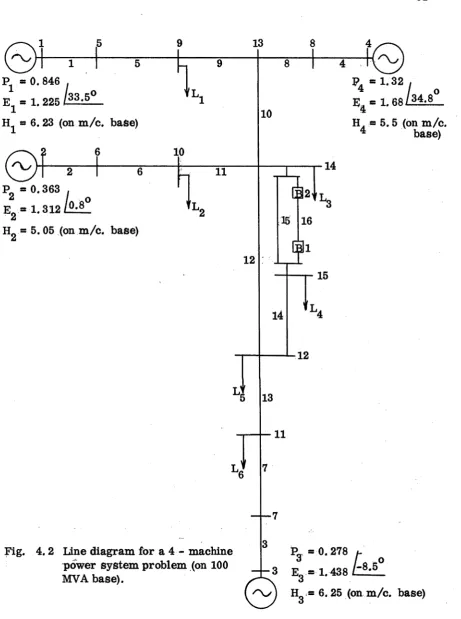
6. 3. 1 4-Machine Problem
189
6. 3. 2 Large Interconnected System
198
6.4 Discussion
218
7.
DISCUSSION
220
7.1 Remarks on the Developed Computational
222
Procedures
7.1* 1 On the Calculation of Processes by Steady-
222
State Techniques
7.1. 2 Limitation of the Studies to the Transient
222
Stability Interval
7.1.3 Integration Errors
223
7. 1. 4 Choice of Step Size "At"
224
7.2 Computational Requirements
228
7.3 Relative Importance of the Various Factors
231
Represented
7.4 Reliability of Data and Accuracy of Prediction
236
7.5 Recommendations Regarding Practical Power
241
8.1 Dynamic Region Studies
244
8. 2 Validity of Induction Motor Model
246
8.3 Considerations of Back Swings of Synchronous
246
Machines
8.4 Considerations of Electrical Transients of
247
Asynchronous Machines
8.5 Man-Machine Interaction and Computer Program
247
Optimization
8.6 Reliability of Data
248
8. 7 Comparison Between Predicted and Actual Power
248
System Behaviour
9.
CONCLUSIONS
249
10. APPENDIX
252
10.1 Solution of Voltages Under Transient Conditions
252
10. 2 Torque-Slip and Current-Slip C haracteristics
255
Versus Frequency
10.3
Normalised Torque-Slip Curves for Induction
256
Motors
10.4 Effect of Number of Poles on Inertia Factor
258
10.5 A ssessm ent of Equivalent P aram eters (Full Load
261
Slip, n , Power Factor, H and I
)
'
om
10.6 Study With Equivalent Circuit
264
10. 7 Study With Proposed Approximate Method
265
10. 8 Effect of Reactive Power on Active Power
266
10. 9 Variations of Input Power to an Inductive Circuit
268
When the Circuit Resistance is Inversely Proportional
to the Current, that is Ro<_l_
I
10.10 Variations of Input Power to an Inductive Circuit
270
When the Circuit Resistance is Independent of
X
SUMMARY
In com prehensive transient and dynamic power system stability studies, the effects of change in instantaneous operating frequency have been hitherto neglected, partly due to lack of adequate methods of treatment, and partly due to considering (erroneously) such effects as insignificant. The present study has shown that neglect of changes in instantaneous frequency in transient stability studies can at the w orst give an erroneous a ssessm en t of stability and even at best can result in a substantially different picture of current and voltage distribution throughout the system when compared with calculations including transient frequency changes.
Methods have been developed to include transient frequency effects in the various power system elem ents as follow
s:-A sim ple vector method, employing the various synchronous machine e . m . f ' s behind their saturated quadrature axis reactances, in conjunction with the instantaneous system admittance matrix, evaluates the instantaneous frequencies of the various bus voltages and branch currents.
Synchronous machine e . m . f ' s and angular momenta are modified in a manner directly proportional to the instantaneous rotor speed to take account of instantaneous rotor angular velocity variations.
x ii
T ra n s m is sio n netw o rk p a ra m e te r v a ria tio n s due to tr a n s ie n t freq u en cy e x c u rsio n s a r e a d ju sted on th e b a s is of th e in sta n tan e o u s fre q u e n c ie s of bus v o ltages fo r shunt b ra n c h e s and of b ra n c h c u r r e n ts fo r s e r i e s b ra n c h e s.
To handle induction m o to r lo ad s on a dynam ic and freq u e n c y - dependent b a s is , a m ethod em ploying th e p ro p e rty of lin e a r ity of th e o p e ra tin g c h a r a c te r is tic s of an induction m o to r (within th e n o rm a l o p e ra tin g ra n g e of slip) h a s been developed. T his m ethod allow s sin g le m o to rs o r g roups of induction m o to rs to b e re p r e s e n te d through th e u s e of th e m o re com m only av ailab le p a r a m e te r s -
h o rse p o w e r, in e r tia fa c to r, full load slip , pow er fa c to r, m ag n etisin g c u rr e n t and efficiency. As a consequence of th is app ro ach , a re a s o n a b le a c c u ra c y in p re d ic te d p e rfo rm a n c e is achieved in th e a b se n c e of a c c u r a te equivalent c irc u it p a r a m e te r s , even when u sing g ro u p s of a ss e m b le d c u rv e s of re p re s e n ta tiv e m ach in e p a r a m e te r s .
S tatic freq u en cy -d ep en d en t lo a d s (for exam ple, m e r c u r y a r c r e c tif ie r s , a r c fu rn a c e s, d is c h a rg e la m p s and e le c tr ic w e ld e rs), a r e tak en account of by a m ethod which em ploys c u rre n t-d e p e n d e n t
in stan tan eo u s effectiv e r e s is ta n c e and freq u en cy -d ep en d en t in d u ctiv e re a c ta n c e , which co n fo rm s to th e a p p ro p ria te p r a c tic a l c h a r a c te r is tic s .
xiv E' q E p E. l f f o f r f k f k£
LI ST OF SYMBOLS
Specific e le c tric loading in Amp. C o n d ./m . Specific m agnetic loading in W b ./S q .m . S e rie s com pensating cap acitan ce.
Slope of the s ta to r c u r r e n t- s lip c h a r a c te r is tic . R o to r d ia m e te r of an induction m o to r.
E . M . F . of m achine m. Load te rm in a l voltage. E . M . F . behind X .
q
In te rn a l m achine voltage p ro p o rtio n al to field c u rre n t. In te r n a l m achine voltage p ro p o rtio n al to q u a d ra tu re axis r o to r c u rre n t.
I n te r n a l m achine voltage p ro p o rtio n al to q u a d ra tu re ax is flux linkages.
I n te r n a l m achine voltage p ro p o rtio n al to d ire c t ax is flux lin k ag es. V oltage behind P o tie r re a c ta n c e ( ) .
V oltage behind d ire c t axis tra n s ie n t re a c ta n c e ( X^ ) . I nstan tan eo u s frequency.
System nom inal frequency.
In sta n tan e o u s frequency c o rresp o n d in g to actu al speed of synchronous m achine ro to r.
In sta n ta n e o u s frequency of voltage at bus k.
hp I
I om I & I -
r s I , & I -
d q
I m
i i-1 J
K, & K -
d q
K K g K
w
k d
-L M M o
H o rse pow er.
In stan tan eo u s c u rre n t.
Negative sequence c u rre n t com ponent. D ire c t c u rre n t com ponent.
M agnetising c u rre n t draw n by an induction m o to r. R eceiving end and sending end c u rre n ts , re sp e c tiv e ly . D ire c t and q u a d ra tu re ax es com ponents of I, re sp e c tiv e ly . C u rre n t supplied to m achine m.
C u rre n t input to node k w ith the e stim a te d voltage. B ran ch c u r r e n t betw een nodes k and ft .
Ite ra tio n ju s t com pleted. Ite ra tio n p reced in g to i. M om ent of in e rtia .
D ire c t and q u a d ra tu re axes sa tu ra tio n fa c to rs , re sp e c tiv e ly . C onstant.
G o v ern o r gain. W inding fa c to r.
Slope of the synchronous m /c . asynchronous to rq u e -s lip c h a r a c te r is tic Inductance of a c irc u it.
In stan tan eo u s a n g u lar m om entum .
A n g u lar m om entum a t sy ste m nom inal frequency.
xvi
n
o Speed at the end of the tim e interval " A t" .
n Instantaneous speed in R .P .M .
n i - Synchronous speed in R .P .M .
n
00 Full load speed in R .P .M .
P Instantaneous active power input.
P .U . - P e r unit quantities.
P
m Mechanical power input to machine m.
P
e E lec trical power output.
P D - Damping power.
P Dn Braking power due to negative sequence c u rre n t.
Ö o i Braking power due to d. c. rapidly decaying component.
P
KVA Synchronous machine rating in KVA.
P
os Position of main valve.
P Number of p a irs of poles and an operator ( —— ).
dt
Q Instantaneous reactiv e power input.
ql & q c - Inductive and capacitive v ars, respectively.
R Instantaneous effective re sista n c e ; equivalent re sista n c e
corresponding to active power input to an induction m otor at a given supply voltage.
R r & X' - T ransm ission line resista n ce and reactance, respectively
R
a A rm ature re sista n c e .
r a - Arc resista n c e .
r i & x i -
r2 &X2
-m axT
oo T T
m ax
T, &T - do qo T! &TT-
do qo T " & T " -
do qo V'
Vk
-AV, V
V,
R e sista n c e equivalent to no - load lo s s e s . S tato r re s is ta n c e and re a c ta n c e , re sp e c tiv e ly .
R o to r re s is ta n c e & re a c ta n c e as r e f e r r e d to s ta to r, re sp ec tiv e ly . Instan tan eo u s slip .
Slip at m axim um to rq u e.
Slip a t the beginning of tim e in te rv a l " A t” . Slip a t the end of the tim e in te rv a l M A t". Full load slip.
Instantaneous m o to r to rq u e. O v erall g e n e ra to r tim e co n stan t. Load to rq u e.
M axim um to rq u e.
O v e rall tu rb in e tim e constant. Dam ping torque coefficient.
D ire c t & q u a d ra tu re ax es open c ir c u it tim e c o n sta n ts, re sp e c tiv e ly . D ire c t & q u a d ra tu re ax es open c ir c u it tra n s ie n t tim e co n sta n ts,
re sp ec tiv e ly . D ire c t & q u a d ra tu re ax es open c ir c u it s u b tra n sie n t tim e co n stan ts,
re sp e c tiv e ly . Infinite bus voltage.
Voltage a t node k.
x v iii
V
r R eceiving end voltage and re fe re n c e voltage. V
s Sending end voltage and stab ilizin g voltage. v t - M achine te rm in a l voltage.
V, &V, - D ire c t & q u a d ra tu re axes com ponents of E , re sp e c tiv e ly
dp dq p
X Equivalent re a c ta n c e co rresp o n d in g to re a ctiv e pow er input to an induction m o to r a t a given supply voltage.
X
e E x tern a l re a c ta n c e . X .& X -
d q D ire c t & q u a d ra tu re axes re a c ta n c e s , re sp e c tiv e ly . X' &X’ -
d q D ire c t & q u a d ra tu re ax es tra n s ie n t re a c ta n c e s , re s p e c tiv e ly . X " & X " -
d q D ire c t & q u a d ra tu re ax es s u b tra n sie n t re a c ta n c e s , re sp e c tiv e ly X3 - M agnetising re a c ta n c e .
Yk i Self and m utual adm ittance betw een nodes k and SL . a k’ ° k ’ ek ’ ^ k i , r k i “ R eal com ponents,
b^, ^k ’ ®k* Bk t ’ r k i “ Im ag in ary com ponents VJ &V -
d q D ire c t & q u a d ra tu re ax es com ponents of V^, re sp e c tiv e ly .
a Slope of to rq u e -s lip and to rq u e -sp e e d c h a r a c te r is tic s .
M agnetising c u rre n t a s fra c tio n of full load c u rre n t. P D ensity of the r o to r m a te ria l.
V E fficiency of the m o to r.
€ Instan tan eo u s deviation in an g u lar velocity.
CO In stan tan eo u s an g u lar velocity. C0
1
Aco Aco’
m
Aco! .
A t 6 m $ $ s $ r * Cos c|) 0 o
e
e,
9oke
$ -ad aq
Synchronous a n g u la r velocity.
A ngular velocity of p h a so r on the X-Y plane.
tt tt t t j tt tt
m
tt tt t t T t t tt
Kl
T im e in te rv a l.P o w e r angle of m ach in e "m ". R esu lta n t a i r gap flux.
Flux p roduced by s ta to r c u rre n ts .
" " " the r o to r m ag n etisin g winding. P h a se an g le betw een & 1^ and & <ä». P o w er fa c to r of an induction m o to r.
P h a se angle of $ a t th e beginning of tim e in te rv a l "A t",
t t t t t t t t end " " "
In stan tan eo u s p h ase angle of voltage p h a so r a t the node k at th e end of tim e in te rv a l "A t" .
In stan tan eo u s p h ase angle of voltage p h a so r a t the node k a t the beginning of th e tim e in te rv a l "A t".
In stan tan eo u s p h ase angle of b ra n c h c u rre n t, k- I a t the end of
th e tim e in te rv a l " A t " .
In stan tan eo u s p h ase angle of b ra n c h c u rre n t, k -f a t the beginning of th e tim e in te rv a l " A t" .
w - A ctive and re a ctiv e p ow ers a t the load bus k (for v a ria b le te rm in a l voltage), re sp ec tiv e ly .
p{ ^ % - A ctive and re a ctiv e pow er loads at node k fo r freq u ency-dependence, re sp e c tiv e ly .
z..
JJ D riving point im pedance fo r m achine j including X .
Q.
z..
Jk T r a n s f e r im pedance betw een m achines j and k including X^. Y X2&134 In stan tan eo u s v alu es of c u r r e n ts through b ra n c h es 1, 2 and
betw een nodes 3 & 4, re sp e c tiv e ly . I
m ax M axim um value of c u rre n t.
t T im e in seco n d s.
X V oltage re g u la to r fo rw ard path gain. T
e " M " " tim e con stan t.
K
s " " stab ilizin g path gain.
T
s " M M " tim e con stan t.
E , f &M - Q u a n titie s p e rta in in g to m achine m at ite ra tio n i
m m m
k' An in te g e r.
V
a Voltage p e r p h a se a c r o s s an induction m o to r (in Fig. 10.1).
Rj+jx;
- E quivalent im pedance of r + jx and jx in p a ra lle l.J . -L o
pe In stan tan eo u s deviation in the bus voltage frequency. p6 R ate of change of pow er angle.
f<v -
Function of (V^ ).O f & o c _
d q D ire c t and q u a d ra tu re ax es a m o r tis s e u r d e c re m e n t fa c to rs , re sp e c tiv e ly .
j&k f i
-A’
The s u b sc rip ts denoting m achine j and m achine k, re sp e c tiv e ly . P h a s e angle.
1
1. INTRODUCTION
Concurrent with the increase in complexity and size of electric
power systems, there has arisen the increasing need for more refined methods
of system planning and assessment. Advances in electronic computing methods
and capabilities have made possible successively improved methods of
calculation, so much so, that it might be expected that not a great deal more
can be achieved without a careful relating of analytical techniques to the
results obtained from full scale tests conducted on power systems, in order
to a ssess the degree of agreement between the predicted and actual system
behaviour. (Unfortunately few such realistic tests have been conducted).
In spite of the great amount of effort devoted to calculation
refinements, however, there seems to have been little attention given to the
study of power system behaviour at frequencies different from normal,
whether during steady-state operation or during transient and dynamic
electro-mechanical excursions - the assumption has been that instantaneous
frequency changes have negligible consequence, particularly in transient
195
and dynamic stability studies
1.1 Historical Development of Power Systems
Prior to 1890, parallel operation of alternators was established
1> 2in isolated instances ’ . Since the first enunciation of the principles of inter
connection by Merz and McLellan (in an address to the British Association in
75
1904
), isolated power stations and isolated electric companies started
interconnections, and as a result, the problem of hunting of synchronous
machines under sudden load changes emerged. This problem did not assume
importance until after the change from belt driven machines to direct
introduction of dampers proposed by Leblanc ’ in France in connection with
84
alternators, and independently by Lamme
in the United States in connection
with synchronous converters.
Small isolated power systems faced the problem of heavy
short-circuit
currents, and in order to reduce their severity and the duty
of the circuit breakers which had to deal with such heavy abnormal currents,
the solution proposed by various authors
was the use of series
current-limiting reactors at various points in the system. These reactors
16
could localize the faults
, thus maintaining the continuity of supply. With
gradual expansion of the small isolated systems, they were interconnected
and integrated into larger systems for the sake of continuity, economy, reli
ability and pooling of technical knowledge and finances, this process
g
requiring high voltage transmission links for mutual transfer of power .
High voltage transmission lines transferring power to
distant load centres and allowing mutual transfer of power between two
electric power systems, have limited capacity, depending upon the sending
end voltage, current, power factor and line impedance. To improve the
32,
maximum limits of power transfer, synchronous condensers were suggested
to be installed on the transmission line routes (for example, ref. 33, shows
an increase of 42% in maximum power limit for a typical high voltage trans
mission line in the presence of synchronous condensers). Later, series
64
resistors were suggested for the same purpose
High voltage lines, because of their excessive charging
currents, created a further problem by requiring too low an excitation of
the synchronous machines under light loads supplied over long distances,
31
thereby causing pole slipping, leading to instability
. To solve this
problem, excitation levels of synchronous machines were adjusted in
3
in order to control system voltages, shunt reactors were employed to over
come the excessive charging currents
With the growth of power system capacities and the increase
in physical distances between generating stations and load centres, extra-
high-voltage transmission lines have been introduced. These are series
compensated by capacitors to overcome their excessive inductive reactances
102,106, 113, 133, 147. The problem of physical distance has been handled
in two
ways:-(a)
By employing d .c. transmission links (which have zero
synchronous length
157).
(b)
By employing tuned transmission lines (i. e. the electrical
220length is increased to more than half wave length
).
Synchronous machines can develop a limited maximum
electrical power depending on the excitation voltage, machine terminal
voltage, machine reactance, and the phase difference between the
excitation voltage and the machine terminal voltage. In the last decade,
the average output of generating sets installed has increased rapidly, and
with improvements in manufacturing techniques, synchronous machines
have become physically smaller for a given output. In turn, this has
resulted in an increase in the natural reactance of the alternators and a
198
system s (instead of d.c. exciters) have resulted in operation of synchronous
machines with equivalent to zero reactance under disturbed conditions 26\
Voltage regulators have made substantial contributions towards the increase
in stability limits of synchronous machines by their quick response and
higher ceiling voltages (reported in the literature from 1928 to date).
Speed governors have also contributed towards stability of synchronous
machines63, 216 - particularly displacement governors 131. Recently,
braking resistors have been employed at the synchronous machine terminals,
237
in order to ensure stable operation during disturbances
In order to supply system load requirements, maximum power
limits for synchronous machines as well as for transmission links must be
taken into consideration for future planning of the power system. The
stability limit, i. e. the maximum power transfer from the generating
station to the load centres via the transmission lines, is usually reached
when the power which can be transmitted over a line or obtained from an
alternator, is a maximum. (As stability and voltage regulation are very
closely associated, stability may also be defined as an ability to maintain
voltage under varying conditions of load for which a system is designed).
In order to meet the system load requirements at all times
under normal and abnormal situations for both the present and the future,
extensive and precise planning is essential, involving knowledge of the
system load requirements from time to time. For this purpose, load
127
surveys
are carried out at regular intervals and load trends are
studied20^ at various key points in the power system to assess the
future demands. Such comprehensive surveys can reveal the correct
loading pattern of the system if based
5
(b)
The demand ascertained by the type of area; high density,
low density, and future saturation.
(c)
Various types of utilization equipment and increasing lighting
intensities.
With the aid of qualitative and quantitative load information
at the various loading centres, the generation, transmission and distribution
system capacities can be made available at the actual required time as far
as possible; otherwise earlier provision of excess capacity will put an extra
burden of untimely investment, while late availability will cause losses in
revenue and inability to meet increasing load demands.
Present day electric power systems include the following
elements
(i)
Synchronous machines - main source of electrical energy,
equipped with; dampers to overcome hunting, to increase
the negative sequence reactance and to overcome the
excessive high voltages under asymmetrical faults;
excitation system to control the wattless current,
maintain system voltages within the declared limits
and to improve the steady-state and transient stability
limits; governors to adjust the active power needed by
the machine at the system nominal frequency and to
facilitate the stable operation of the entire system under
disturbed conditions.
(iii) S e rie s r e a c to r s - to red u ce th e m agnitude of s h o rt c irc u it c u rre n ts w ith w hich the c ir c u it b r e a k e r s have to deal; to lo c alize fa u lts fo r continuity p u rp o se s; to red u ce lam p flic k e r c au se d by violently flu ctu atin g loads (for exam ple caused by a r c fu rn ac es).
(iv) Shunt r e a c to r s - to n e u tra lis e th e e x ce ssiv e ch arg in g c u rre n ts draw n by high voltage lin e s .
(v) S e rie s c a p a c ito rs - to n e u tra lis e p a rtly the e x ce ssiv e inductive reactan ce of e x tra high voltage lin e s; to in c re a s e th e ir p o w e r-c a rry in g c ap a c itie s, and to red u ce the violent fluctuations in re a c tiv e pow er draw n by a p p a ra tu s such as e le c tric w e ld e rs.
(vi) Shunt c a p a c ito rs - to im prove th e o p eratin g pow er fa c to r of the loads at the load c e n tre s and to re g u la te the load voltages.
(vii) Synchronous c o n d en se rs - to supply the w a ttle ss c u rre n t a t the load c e n tr e s , to re g u la te the load voltages and to in c re a s e the pow er tr a n s f e r lim its of high voltage lin e s. (viii) Shunt r e s i s t o r s - fo r synchronous m achine b rak in g under
d istu rb e d conditions.
(ix) S e rie s r e s i s t o r s - to in c re a s e th e m axim um pow er tr a n s f e r lim its of tra n s m is s io n lin e s .
7
1 .2 P o w e r System Studies
F ro m the view point of econom y, safety and re lia b ility of supply under actu al conditions of loading fo r both p re s e n t and fu tu re sy ste m re q u ire m e n ts, knowledge of the p e rfo rm a n c e of the v a rio u s pow er sy ste m e lem en ts is e ss e n tia l. F o r a s s e s s m e n ts of p e rfo rm a n c e un d er th e w o rs t p re d ic te d situ atio n s, p ra c tic a l te s ts a re v ery expensive and d ifficu lt to c a r r y out, so that m odel te stin g has to be re lie d upon to a v e ry la rg e extent. Such m odels m ay be p h y sical o r m a th e m atica l.
P o w er s y ste m p e rfo rm an c e a s s e s s m e n t involves: load flow in key tra n s m is s io n lin e s and fe e d e rs ; sta b ility under s te a d y -s ta te and d istu rb e d conditions - the sta b ility of a pow er sy ste m is its cap ab ility to rid e through a change in sy ste m dem and w hich m ay be g rad u al o r
instan tan eo u s, and may a lso b e defined as its ab ility to resp o n d to th e p o w er dem ands fo r which it has b een designed.
S e rie s c u rre n t lim itin g r e a c to r s made th e ir way into pow er sy ste m s a s the only solution fo r reduction of s h o r t- c ir c u it c u r r e n ts . In o rd e r to evalu ate the m agnitudes of s h o r t- c ir c u it c u r r e n ts , a n aly tica l
19 tech n iq u es, to g eth er w ith p ra c tic a l te s ts w e re p re se n te d by D iam ant , but th e re w as m ark ed d is a g re e m e n t betw een th eo ry and p ra c tic e . D oherty
23
and S hirley subsequently introduced re fin e m e n ts, fo r exam ple, by including leakage fa c to rs in calcu latin g the tra n s ie n t re a c ta n c e s fo r the sy n chronous m ach in es fo r tre a tm e n t in s h o r t- c ir c u it stu d ie s - th is produced b e tte r a g r e e m en t betw een th eo ry and p r a c tic e .
Sm all in terco n n ected pow er s y ste m s faced the p ro b le m of s te a d y -s ta te stab ility lim its , w h e re a s the tra n s ie n t s ta b ility p ro b le m w as
7
of a phasor diagram to determine the maximum power transfer between two
synchronous machines running in parallel. Such interconnected systems
involved high voltage transmission links for mutual transfer of power, and
the problem of limited power transfer through a given line was soon met.
9
Philip presented a circle diagram in 1911 to determine the maximum
power transfer over a transmission line with varying R:X ratios. Subsequent
25
calculations were presented also by Steinmetz
.
The transmission
problem was tackled analytically by employing generalized transmission
32 33
line constants
’
, and the calculations compared with measurements on
a 2300V and 625 KVA line with good agreement between theory and practice;
the authors also suggested the use of synchronous condensers, to improve
the maximum power transfer limit (as indicated in section 1.1).
21
In 1917, Johnson
pointed out the latent introduction of
instability due to the excessive use of series reactors to reduce the
magnitude of short-circuit currents in a system under disturbed conditions.
22In the same year, Juhnke
also mentioned the transient stability problem
24
in relation to the use of series current limiting reactors. In 1920, Schuchardt ,
described some instances of unstable operation of certain alternators on
American systems, and suggested the elimination of series reactors used
for current limiting purposes. In Britain, the power system grid was
expanding and the deficiency of synchronising power able to be carried by
27
transmission lines was causing problems
A simplified representation of a synchronous machine by a
fixed e. m. f . acting behind transient reactance followed from the constant
23
flux-linkage theorem put forward by Doherty and Shirley
in 1918, and was
27
9
u sefu l fo r s h o r t- c ir c u it c u rre n t calcu latio n s, a s em ployed by F ran k lin in 37
1925 On the o th e r hand, Spencer and Hazen fe lt the an aly tical techniques too difficult and tedious, and consequently in 1925, they b u ilt a sm all s c a le m odel of a pow er sy ste m , re p re se n tin g the s o u rc e s by p h ase shifting
tr a n s f o r m e r s , tr a n s f o r m e r s by th e ir equivalent c irc u its , and tra n s m is s io n lin e s and sy ste m loads by lum ped im p ed an ces a t sy ste m nom inal freq u en cy .
By th is tim e, pow er sy ste m s had becom e quite com plex, and e n g in e e rs w e re m eeting p ro b lem s w ith the tr a n s ie n t s ta b ility lim its fo r the
42 47 45
e n tire sy ste m ’ . In 1926, S h irley pointed out the p ra c tic a l sta b ility lim its in supplying c e r ta in c la s s e s of load, even w ith s h o rt lin e s . The loads w e re c la s s ifie d a s :
-(1) C onstant pow er output - induction m o to rs w ith p ra c tic a lly con stan t sh aft output, such as those d riv in g fans, pum ps, c o m p re s s o rs , d ir e c t- c u r r e n t g e n e ra to rs; synchronous m o to rs fo r the sam e c la s s e s of s e rv ic e as fo r induction m o to r s .
(2) V ariab le im pedance - synchronous c o n v e rte rs supplying pow er to s e r ie s m o to rs fo r railw ay s e rv ic e .
(3) C onstant im pedance - lighting, heating, e le c tric fu rn ac es, w e ld e rs, and synchronous c o n v e r te r s fo r lig h tin g load. (4) M iscellan eo u s - com bination of co n stan t pow er, v a ria b le
im pedance, and c o n sta n t im pedance lo ad s.
The e m p h asis w as p laced on a ctiv e and re a c tiv e pow er dem ands a s affected by the te rm in a l voltage and not on th e in stan tan eo u s freq u en cy in flu en ce.
47
A n aly tical so lu tio n s re g a rd in g the b ehaviour of synchronous m ach in es under s te a d y -s ta te and tra n s ie n t conditions, such as cyclic v a ria tio n s of im p re s s e d to rq u e, sudden a n g u lar d isp la c e m e n t, sy n ch ro n isin g out of
p h ase and s h o r t- c ir c u its , w e re p re s e n te d by D oherty and N ickle46 and K u " . Subsequently, a co m p lete 2 -»reaction th e o ry of synchronous m ach in es, f i r s t
53
enunciated by B londel, w as p re se n te d by P a r k in 1929. A sim p lified 50
s te p -b y -s te p m ethod su g g ested by P a r k and B an ck er fo r synchronous m achine calc u la tio n s w as developed in d e tail by Longley81^1" ^ , on the b a s is of P a r k ’s two re a c tio n th eo ry , to c alc u la te the swing c u rv e s fo r synchronous m ach in es u n d e r d istu rb e d conditions fo r s y m m e tric a l 3 -p h ase
65
fa u lts. Following th is , C lark e in tro d u ced s y m m e tric a l com ponents fo r a sy m m e tric a l and sim u ltan eo u s fau lts by developing s p e c ia l equivalent c ir c u its fo r such fa u lts. The two re a c tio n th eo ry f o r the synchronous m achine w as fu r th e r extended to include s a tu ra tio n , a rm a tu re c irc u it
68 81
c ap a c itan c e , d a m p e rs and a b alan ced te rm in a l im pedance by P a r k , C ra ry , C o n co rd ia89, 85 and Ku86 re sp e c tiv e ly .
The in c r e a s e d com plexity of e le c tr ic p o w er s y ste m s
dem anded a co m plete a n a ly s is , but due to com puting d ifficu lties, a n aly tical 57
tech n iq u es w e re b a se d on the following sim plifying a ssu m p tio n s : -(a) R e s is ta n c e and c ap acitan ce w e re neglected.
(b) R ea c tan c e s in the d ir e c t and q u a d ra tu re ax es w e re c o n sid e re d e q u a l.
(c) N orm al voltage w as m ain tain ed u n d er s te a d y -s ta te conditions on the h ig h -ten sio n side of tr a n s f o r m e r s a t the g e n e ra to r end. (d) The p o w er f a c to r a t the high ten sio n side w as n o rm a lly 0. 98
11
(e) Flux linkages behind tra n s ie n t re a c ta n c e of the g e n e ra to r and m o to r w e re c o n sid e re d to re m a in co n stan t during the f i r s t swing.
(f) M agnetic sa tu ra tio n w as neglected. (g) Damping to rq u e s w e re neglected.
(h) R esu lts w e re b a se d on the f i r s t swing only.
(i) F au lts w e re c o n sid e re d only on the high ten sio n sid e of the unit tra n s f o r m e r .
(j) C onstant shaft to rq u e assu m ed .
(k) G ov ern o r, voltage re g u la to r action and lo a d -sp ee d c h a r a c t e r ^ s tie s w e re n eg lected .
( f ) C hanges in in stan tan eo u s synchronous m achine sp ee d s w e re n eg lected .
All the above assu m p tio n s provided sim p lified m a th e m a tic a l m odels to c a r r y out pow er sy ste m stu d ie s, in p a r tic u la r n eg lectin g the change in speed of the synchronous m ach in es, which p e rm itte d tre a tin g the tr a n s m is s io n and d is trib u tio n n etw o rk s and the pow er sy ste m loads at sy ste m n o m in al freq u en cy .
Since the developm ent of th e 2 -r e a c tio n th eo ry , the a s s e s s m e n t of p e rfo rm a n c e fo r pow er sy ste m elem en ts by p h y sical m odels w as p r e f e r r e d in the face of d ifficu lt a n aly tica l techniques. T h ese techniques w e re con tin u ally re fin e d fo r v a rio u s individual elem en ts : fo r exam ple, synchronous m ach in es - re fin e d to include dam ping and sy n ch ro n izin g to rq u e s, and the c h a r a c te r is tic s of au to m atic voltage re g u la to rs and g o v e rn o rs; induction m o to rs - including dam ping and tra n s ie n t a n a ly sis during sw itching and faults; high voltage d ire c t c u r r e n t tra n s m is s io n s y ste m s .
M ost of the a n a ly tic a l stu d ies w e re b ased on a sin g le m achine supplying an infinite bus, e ith e r d ire c tly o r through an e x te rn a l im pedance,
74 76
At th is stag e , the pow er sy ste m stu d ies w e re c la s s ifie d a s : -(1) Load flow s tu d ie s.
(2) S te a d y -state s ta b ility stu d ies. (3) T ra n s ie n t s ta b ility s tu d ie s.
The load flow stu d ie s did not p r e s e n t m any p ro b le m s and could 99, 104, 132
e a s ily be c a r r ie d out on A .C . and D .C . calcu latin g b o a rd s 60, 88, 89, 111, 120,150, 155
, and on
A. C. netw ork a n a ly z e rs w ith the synchronous
71 m ach in es being re p re s e n te d by e . m . f ' s acting behind equivalent re a c ta n c e s , and tre a tin g the r e s t of the sy ste m by equivalent c irc u its at sy ste m nom inal freq u en cy .
R egarding s ta b ility stu d ie s, im proved m odels w e re developed, in w hich the synchronous m ach in es w e re re p re se n te d by sim u latio n tech n iq u es
00 110
’ , (with e . m . f ' s c o rre sp o n d in g to the excitation, and th e ir p h ase angles c o rre sp o n d in g to the g o v e rn o r s e ttin g s). Such m odels w e re quite s a tis fa c to ry fo r c a rry in g out s te a d y -s ta te s ta b ility stu d ie s, but fo r tra n s ie n t s ta b ility , the n e c e s s a ry s te p -b y -s te p ad ju stm en ts of the m agnitudes and p h a se s of th e m achine e . m . f ’s w e re tim e consum ing and ted io u s. In 1950, a m odified m odel sy ste m w as developed in w hich the synchronous m achine u n its w e re
121 149
re p la c e d by m ic ro -m a c h in e s ’ of v ery low pow er (1-10 KVA), in w hich the o p eratin g c h a r a c te r is tic s of the m odels w e re intended to c o rre sp o n d to those of the full size m ach in es; how ever, th e re w as s till a m a rk e d d ifferen c e
173
in re s u lts w hen co m p ared to a ctu a l te s ts on a sy ste m . In 1955, a dynam ic 150
a n a ly z e r w as b u ilt by Kaneff , w hich o ffered a ran g e of sca lin g by changing the value of c a p a c ito r in the m achine u n its and the re s u lts a g re ed w ith the s te p -b y -s te p in te g ra tio n m ethods of the swing equation. F u ll-s c a le sta b ility
173
te s ts c a r r ie d ou t in 1958 on the 132 KV B rita in g rid co n firm ed the
13
Since the beginning of the era of digital computers, mathematical
models for complex power systems have been rapidly developing, as they offer
as detailed a treatment of power system elements as one has the ingenuity
and the information to include; moreover, physical models have their own
inherent limitations which make them in many respects less attractive than
digital methods. Stability studies on high speed digital computers have taken
into account all the simplifying assumptions (a to k above) which were adopted
in the past due to computing difficulties. Comprehensive digital computer
214, 216, 229,246
programs have been developed to carry out such stability studies
1.3 The Importance of Power System Frequency
As already mentioned, present day stability studies make use
of modern high speed digital computers, which offer as detailed a representa
tion of the various power system elements as the state of knowledge and
practice permit. Limitations are in fact due to the absence of adequate
methods for detailed representation and the lack of necessary information
on appropriate system data.
Of the simplifying assumptions mentioned in the previous
sections, only (i ), that is, changes in instantaneous synchronous machine
speeds, has hitherto been ignored in calculation refinements.
power controller will take the necessary action under normal and emergency
conditions when there is a shortage of spinning reserve. In general, induction
motor loads predominate in a power system, and consequently the operating
frequency of the system has proved to be a very powerful adjustable
parameter available to the power controller119,
.
Under transient disturbance conditions, the rotors of the
various synchronous machines will be subjected to deviations in speed from
the normal steady »state system nominal value, giving rise to transient
changes in instantaneous frequencies of voltages and currents throughout
the system. The magnitude of these frequency changes may amount to
several percent of system frequency as discussed in Section 2. Transient
variations in frequency throughout the system affect the performance of
the various power system elements as follows:
(i)
The instantaneous stored energy in the rotating parts of the
synchronous machines and the machine e .m .f's vary. The
effect on machine e. m. f. has been dismissed in a purely
inductive circuit in reference 195, even though the constant
magnitude of current at a changed value of machine e . m. f .
will be followed by a change in active and reactive power.
This neglect of change in instantaneous frequency has
permitted the equating of P.U. torque to the P.U. power
(which is not in fact true).
15
machines develop various damping and opposing torques
(due to interaction of the ro to r and the resultant a ir gap
flux) in addition to their electrical output torques. The
damping torques may be positive or negative depending
upon the slip of the ro to r with respect to the resultant
a ir gap flux. The existing practice has been to consider
such damping torques as directly proportional to the
instantaneous slip of a synchronous machine rotor with
respect to an infinite bus voltage in the case of a single
machine connected to an infinite bus, (whether through an
external reactance or not), whereas in a multi-machine
case, the instantaneous slip has been considered with
respect to the Thevenin’s equivalent e. m .f. in series
with the short circuit impedance when the machine under
103
consideration is disconnected
. This treatm ent will
always give damping in the positive direction whether the
machine sta rts accelerating o r decelerating under
disturbed conditions. The treatm ent presented in
ref. (224) considers the damping torque as proportional
to the rotor slip with respect to the term inal voltage, on
the basis of the argument that the machine views the
remaining power system network through its term inals r
this is erroneous because the damping torque in fact
depends on the relative speed between the rotor and the
resultant a ir gap flux.
netw o rk p a r a m e te r s w ill u p set th e c u rre n t and voltage d is trib u tio n s in the e n tire sy ste m , re su ltin g in e rro n e o u s se ttin g s of p ro te c tiv e re la y s and of tap-settings of v ario u s pow er and d is trib u tio n tr a n s f o r m e r s .
(iv) The activ e and re a c tiv e pow er dem ands of the pow er sy ste m lo ad s (which d e term in e the sy ste m p e rfo rm an c e under n o rm a l and a b n o rm al situ atio n s) v a ry . The m o re usual loads m et in p r a c tic e include : induction m o to rs, synchronous m o to rs, filam e n t lam p s, elem en t h e a te rs , d isc h a rg e lam p s, a r c - fu rn a c e s , e le c tric w e ld e rs, and m e r c u r y - a rc r e c tif ie r s ; a ll of w hich a re voltage-dependent, and except fo r filam en t la m p s and elem en t h e a te rs , a r e also frequency-dependent. The p o w er sy ste m loads have p rev io u sly been re p re se n te d in tr a n s ie n t and dynam ic s ta b ility stu d ie s in v ario u s w ays, fo r exam ple by:
-(1) C onstant shunt im pedance at sy ste m nom inal frequency, giving activ e and re a c tiv e pow er d ire c tly p ro p o rtio n al to the s q u a re of the te rm in a l voltage.
(2) C onstant c u r r e n t sin k s, giving activ e and re a c tiv e pow ers d ire c tly p ro p o rtio n al to the te rm in a l voltage.
(3) N o n -lin e a r loads.
Loads have been r e p re s e n te d in a v ery d etailed m an n er in r e fe re n c e 247, b y
:-a + b V k d + e V,
k
2
+ c V, k 2 + f ’ V,
k
(a, b, c, d, e andf’) are the constants as determined by the
load data and the load characteristics); and by
17
k
i k v1 ^ V
= Q i k <i H- k2(pe)k)
for their instantaneous frequency-dependence, where k^
and k are constants and (p0) is the instantaneous deviation
in the bus voltage frequency from its nominal value.
All the usual representations of power system loads have
hitherto treated the loads as static and independent of frequency, except
in the case of ref. 247, in which it is suggested that the loads may be
represented as in the relations P£ an
dependent on frequency deviation. However, although some loads may
depend linearly on frequency deviations, others (for example, arc-furnaces
and electric welders) do not. Clearly, a more complex relationship between
the frequency deviation and load deviations must be introduced.
d Qj^ above - that is, linearly
1.4 Objective of the Present Project
2. INSTANTANEOUS FREQUENCY VARIATIONS ON A POWER SYSTEM
Under disturbed conditions, the various synchronous machines
on a power system move at varying angular velocities, different from their
steady-state values, thereby producing instantaneous frequency deviations,
from system nominal values, of the voltages and currents throughout the
system. Such transient deviations of frequency affect the performance of
the various power system elements, as has already been suggested in
Section 1.
2.1 Magnitude of Frequency Excursions
It can be shown by a simple approximate argument that in
extreme cases, frequency excursions on power systems of up to + 5% of
142
synchronous frequency can occur
. More commonly, however, excursions
of up to + 2% may be expected in normal configurations (see, for example,
ref. (195), page 6); this figure has been confirmed by the author for various
different systems which have been studied by the methods presented herein.
(For example, see figure 3.6 (c)).
The general magnitude of instantaneous frequency excursions
has been long appreciated; however, awareness of the order of quantitative
effects produced on the system, particularly in relation to transient and
dynamic stability, has been lacking - indeed, the effect has been considered
195
negligible
. It will later be evident that including instantaneous frequency
excursions in calculations of transient stability can have an important signifi
cance.
2.2 Assessm ent of Instantaneous Frequency
19
of the fault, the instantaneous rotor angular velocities of each machine will
deviate from co^, the synchronous value.
LOAD
LOAD
Fig. 2. 1 Power system illustrating assessment of instantaneous frequency.
Under disturbed conditions, the e . m. f . and current phasors
will move with respect to a reference phasor moving with synchronous angular
velocity, as shown in fig. 2.2, by small, and in general different, angular
velocities. Thus phasors I , I
I , E , and v will follow E and E with
1 A o 4 O £ 1 ct
different relative angular velocities depending on the instantaneous values of
reactance voltages in the circuit : these values can be found from a knowledge
of the instantaneous frequency of the current passing through the various parts
of the system, and in general under disturbed conditions, the instantaneous
frequency of the above quantities will be different from synchronous.
In figure 2.1, the machines may swing either in the same
direction, in which case the frequency
of all phasors follows these swings
at different rates, or they may swing in opposite directions, when phasors
1^ and I2 will follow their respective machines, with
following either 1^ or
I2 depending on whether machine l o r machine 2 respectively is dominant.
Let L
= I
„ sin cot
1
maxi
Fig. 2. 2 Phasor diagram on X-Y plane.
Where co and oo + « are the instantaneous angular velocities
max21
of phasors I
. and I
oJ respectively,
maxi
assuming I
= I
1,
maxi
max2
then
i A = sin wt + sin ( co + «':) t
34
= 2 sin ( co + e / ) t . cos (e / 2) t
(2.1) [image:42.523.48.493.64.621.2]21
in instantaneous angular velocity is 1% from its nominal value, the contribution
by the term cos € /g t during the time interval of 0. 05 sec. is to reduce the
magnitude of the sine wave by 0. 3%, whereas when € =
is 0.07%.
tt
/
2, the reduction
For zeros of i_ .,
34
sin ( w + e ) t = - sin w t
(2.2)
The equation (2.2) will be satisfied if,
(a? + e ) t
=
2
t tk’ +
ß(2.3)
and
w t
=
2
TTk’
- ß(2.4)
Adding equations (2. 3) and (2. 4) and dividing by 2,
Cüt + € t y
=
2 7T k ’
or the instantaneous angular velocity of the phasor I
= u + € / 2 (2 .5 )
On the basis of the assumption that 1W
CÜC) = I^ ^ ^ th e additional term €/g in
equation (2. 5) represents the average deviation. In the case where I is
dominant, the contribution by the additional term will be very small, whereas
a dominant contribution of I will bring this additional contribution in equation
(2.5) close to e when I
o. The instantaneous variations of 1 ^ will follow
approximately a sine law but with changing frequency. Therefore, the
In order to account for the situation arising on an actual power
system where, during transient disturbances, changes in instantaneous
freqrency of voltages and currents occur on different parts of the system as
a result of acceleration and deceleration of the synchronous machines, it is
possible to determine the instantaneous contribution of current in each
particular branch of the system made by each machine or machine group.
2. 2. 1 Partial Differentiation Method
In order to determine the instantaneous resultant current
both in magnitude and phase in a branch of the transmission network, the
contributions of current by individual machines towards the total current
in a particular branch should be known. Then, by applying the principles
of superposition, the resultant currents can be evaluated both in magnitude
and phase. The instantaneous current in the branch between buses k and 1 is,
I
_
2
k
a ~
3 9 1,
x I.
J
(2. 6)This information is required many times for each branch
(as shown in section (4.1.1.2)), at each interval of time during a transient
stability study, and this becomes a very time consuming part of the
calculation procedure on a digital computer.
2. 2. 2 Rotating Phasor Method
23